What Is a 100nF Capacitor and How Do You Choose the Right One
13 min
- What Is a 100nF Capacitor?
- How to Read 100nF Capacitor Marking: 104, 0.1 µF, and Unmarked SMD Parts
- What Is a 100nF Capacitor Used For?
- 100nF Capacitor Types: Ceramic, Film, and Electrolytic
- How to Choose a 100nF Capacitor
- Can You Replace a 100nF Capacitor with a Different Value?
- 100nF Capacitors in JLCPCB PCB Assembly
- Conclusion
- FAQs About the 100nF Capacitor
Key Takeaways
- Value: A 100nF capacitor has a nominal capacitance of 0.1 µF, or 100,000 pF, and all three names describe the same part value.
- Marking: Many through-hole ceramic and film capacitors use the three-digit code 104, while most SMD MLCCs are unmarked.
- Main use: Its most common function is local decoupling at an IC power pin, where it supplies fast transient current and shunts high-frequency noise to ground.
- Default choice: For general decoupling, an X7R or X5R MLCC is a common starting point; 0402 and 0603 are widely used package sizes.
- Selection rule: Choose the dielectric, voltage rating, and package together, because a Class 2 ceramic capacitor can lose a significant share of its capacitance under DC voltage.
A 100nF capacitor is a 0.1 µF capacitor, usually marked 104 on leaded parts. It is the capacitor most often placed beside the power pins of an integrated circuit, and it is also used for signal coupling, noise filtering, and RC timing.
The same nominal value can behave differently depending on its dielectric, voltage rating, and package, so a part chosen by capacitance alone may deliver less effective capacitance than the schematic indicates.
In this guide, you will learn:
- What a 100nF capacitor is and how its value converts between nF, µF, and pF
- How to read the markings on ceramic and film 100nF capacitors
- Where 100nF capacitors are used and why the value is so common
- How to choose the type, dielectric, voltage rating, and package
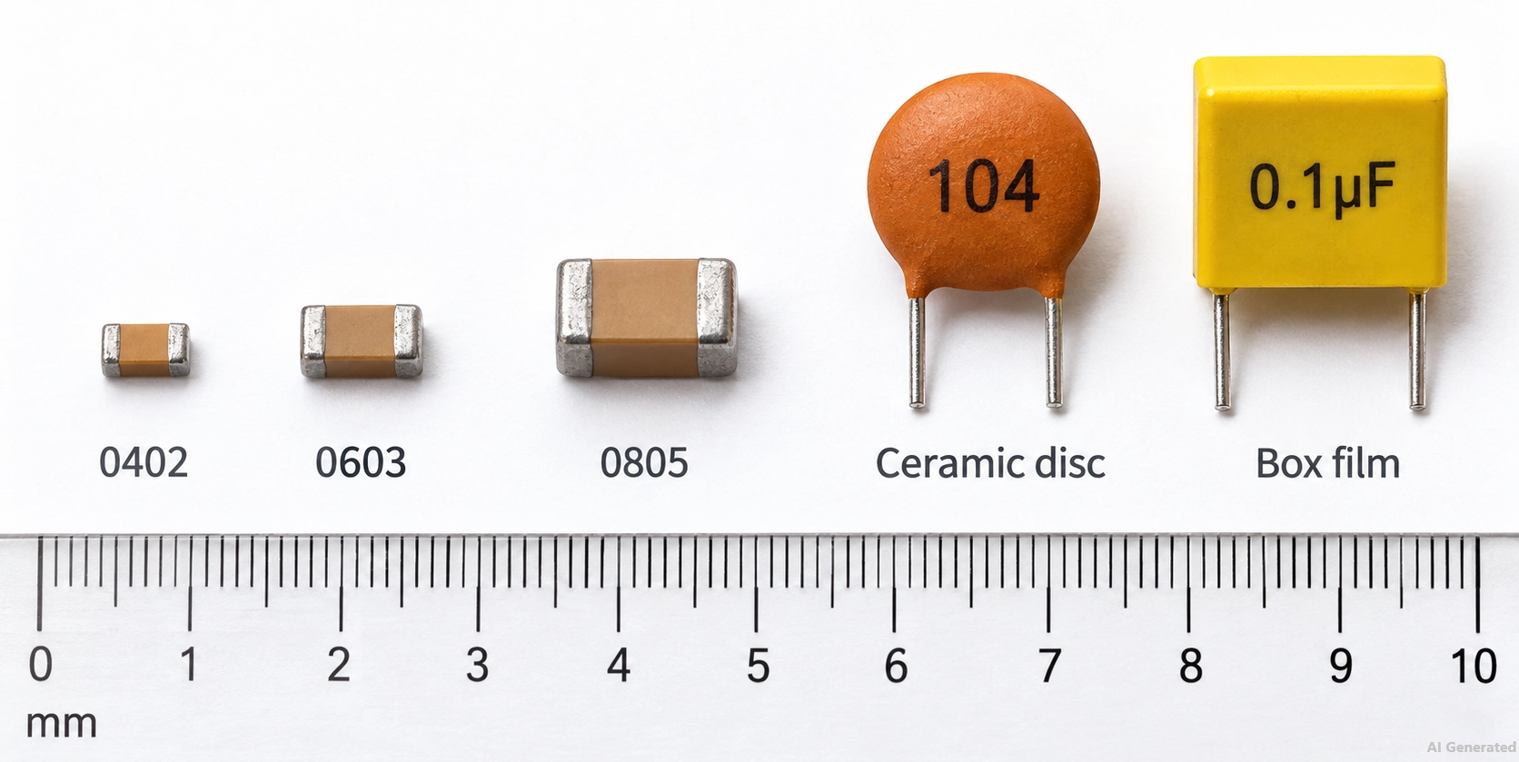
Figure: 100nF capacitors in 0402, 0603, and 0805 MLCC, ceramic disc, and box packages.
What Is a 100nF Capacitor?
A 100nF capacitor is a capacitor with a nominal capacitance of 100 nanofarads, which equals 0.1 microfarad (µF) or 100,000 picofarads (pF).
100 nF and 0.1 µF are equivalent notations for the same nominal capacitance. Both appear commonly in schematics, datasheets, and BOMs.
| Notation | Value | Where You See It |
|---|---|---|
| Nanofarads | 100 nF | Schematics, BOMs, and European datasheets |
| Microfarads | 0.1 µF | US datasheets, reference designs, and film capacitor bodies |
| Picofarads | 100,000 pF | The base unit behind the three-digit code |
| Three-digit code | 104 | Leaded ceramic and film capacitor bodies |
| Letter as decimal point | 100n or u1 | Schematics and small capacitor bodies |
Capacitance alone does not describe the part. When selecting a 100nF capacitor, five key parameters are typically considered:
- Capacitance: 100nF, often written as 104 in the part number
- Tolerance: typically ±5%, ±10%, or ±20%
- Voltage rating: the maximum continuous DC voltage
- Dielectric: C0G, X7R, X5R, or Y5V for multilayer ceramic capacitors (MLCCs)
- Package: the case size, such as 0402 or 0603
How to Read 100nF Capacitor Marking: 104, 0.1 µF, and Unmarked SMD Parts
The most common 100nF capacitor code is 104. The first two digits are the significant figures, and the third digit is the number of zeros, with the result in picofarads: 10 followed by four zeros gives 100,000 pF, or 100nF.
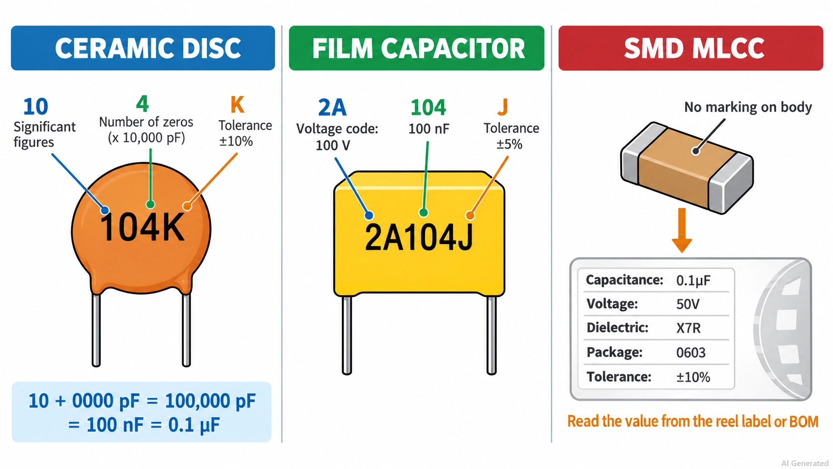
Figure: 100nF capacitor markings on a ceramic disc, a film capacitor, and an SMD reel.
A suffix letter after the code gives the tolerance, and a prefix on film capacitors gives the voltage rating:
| Marking | Where It Appears | Meaning |
|---|---|---|
| 104 | Ceramic disc and leaded MLCC | 100,000 pF = 100nF |
| 104J, 104K, 104M | Ceramic and film bodies | 100nF with ±5%, ±10%, or ±20% tolerance |
| 104Z | Low-cost ceramic discs | 100nF with −20% to +80% tolerance |
| 2A104J | Film capacitors | 100 V rating (2A), 100nF, ±5% |
| 0.1 or .1 | Box and dipped film capacitors | 0.1 µF |
| u1 or 100n | Small film bodies and schematics | 0.1 µF, with the letter in place of the decimal point |
| No marking | SMD MLCCs | Identify from the reel label, part number, or BOM |
Ceramic chip capacitors usually carry no printed value, so a 100nF MLCC is identified from its reel label, manufacturer part number, or BOM, as our guide to SMD capacitor codes explains.
What Is a 100nF Capacitor Used For?
A 100nF capacitor is used mainly for local decoupling. It sits between an IC power pin and ground, supplies the fast current pulses that switching logic draws, and shunts high-frequency noise away from the supply rail.
Common 100nF capacitor uses include:
- Decoupling at IC power pins: One 100nF capacitor per power pin is a common starting point, placed as close to the pin as practical.
- Filtering: In RC and LC filters, it sets the corner frequency together with the resistor or inductor, for example, on ADC inputs and sensor lines.
- AC coupling: In series between two stages, it blocks the DC level and passes the signal. With a 10 kΩ load, the cutoff frequency is about 159 Hz.
- Reset and debounce circuits: With a pull-up resistor, it sets the delay on the MCU reset pins and switch inputs. A 10 kΩ resistor and 100nF give a 1 ms time constant.
- Snubbers and EMI suppression: Film 100nF capacitors are used in RC snubbers across relay contacts and, as safety-rated parts, across AC mains inputs.
Why Is 100nF Commonly Used for Decoupling?
At 1 MHz, an ideal 100nF capacitor has a reactance of about 1.6 Ω, and at 10 MHz, about 0.16 Ω. This low impedance across the frequency range of digital switching noise is one reason 100nF became the standard local decoupling value.
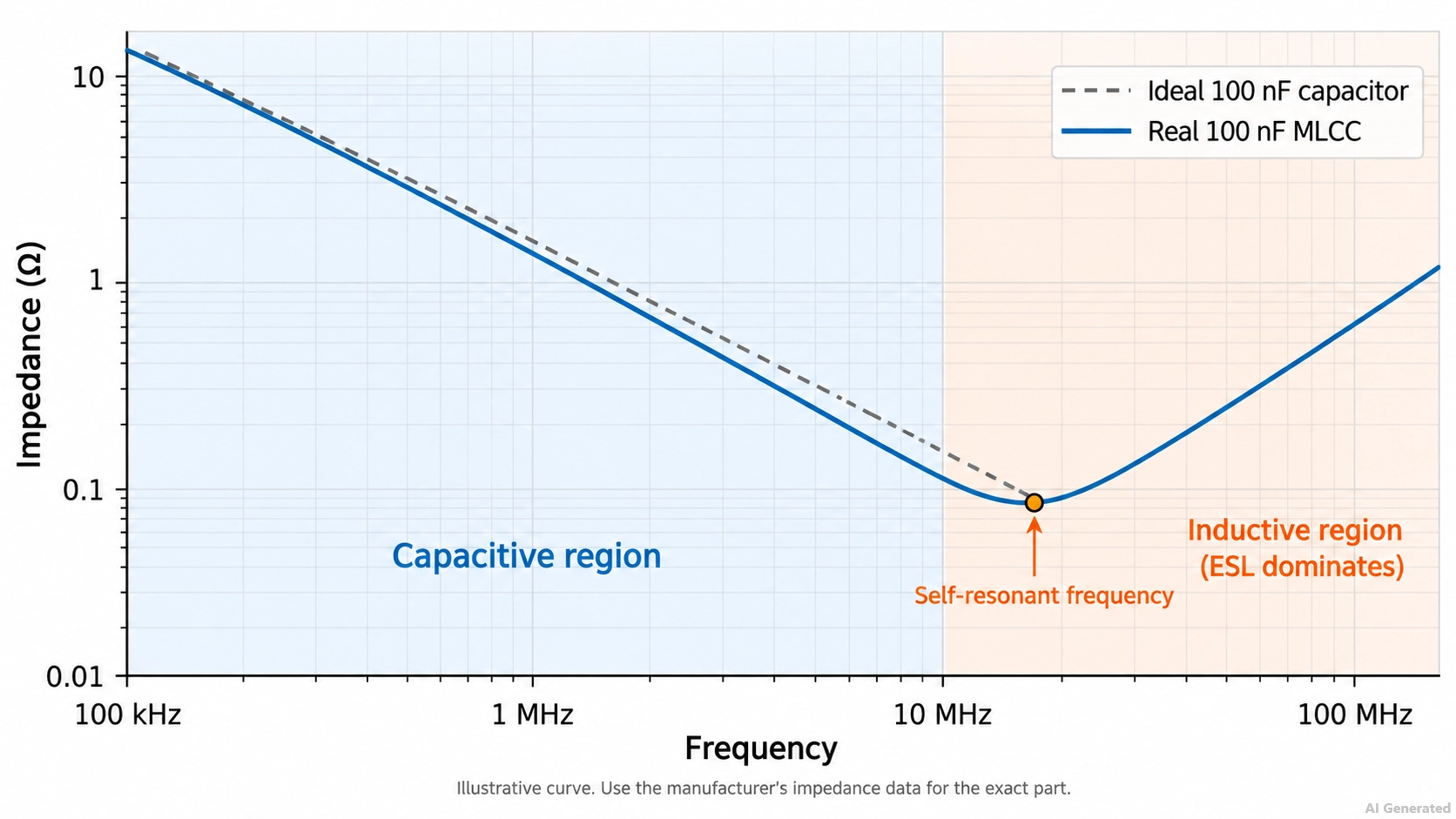
Figure: Impedance of a real 100nF capacitor.
| Frequency | Reactance of an Ideal 100nF Capacitor |
|---|---|
| 100 kHz | 15.9 Ω |
| 1 MHz | 1.59 Ω |
| 10 MHz | 0.16 Ω |
A real capacitor also has equivalent series inductance (ESL) from its package, pads, and vias. At its self-resonant frequency, the capacitive and inductive reactances cancel, and the impedance reaches its minimum. Above that frequency, the ESL dominates, and the impedance rises again.
With about 1 nH of total mounted inductance, a 100nF capacitor resonates near 16 MHz. The actual frequency depends on the package, pad layout, and via placement, so check the manufacturer's impedance curve for the exact part.
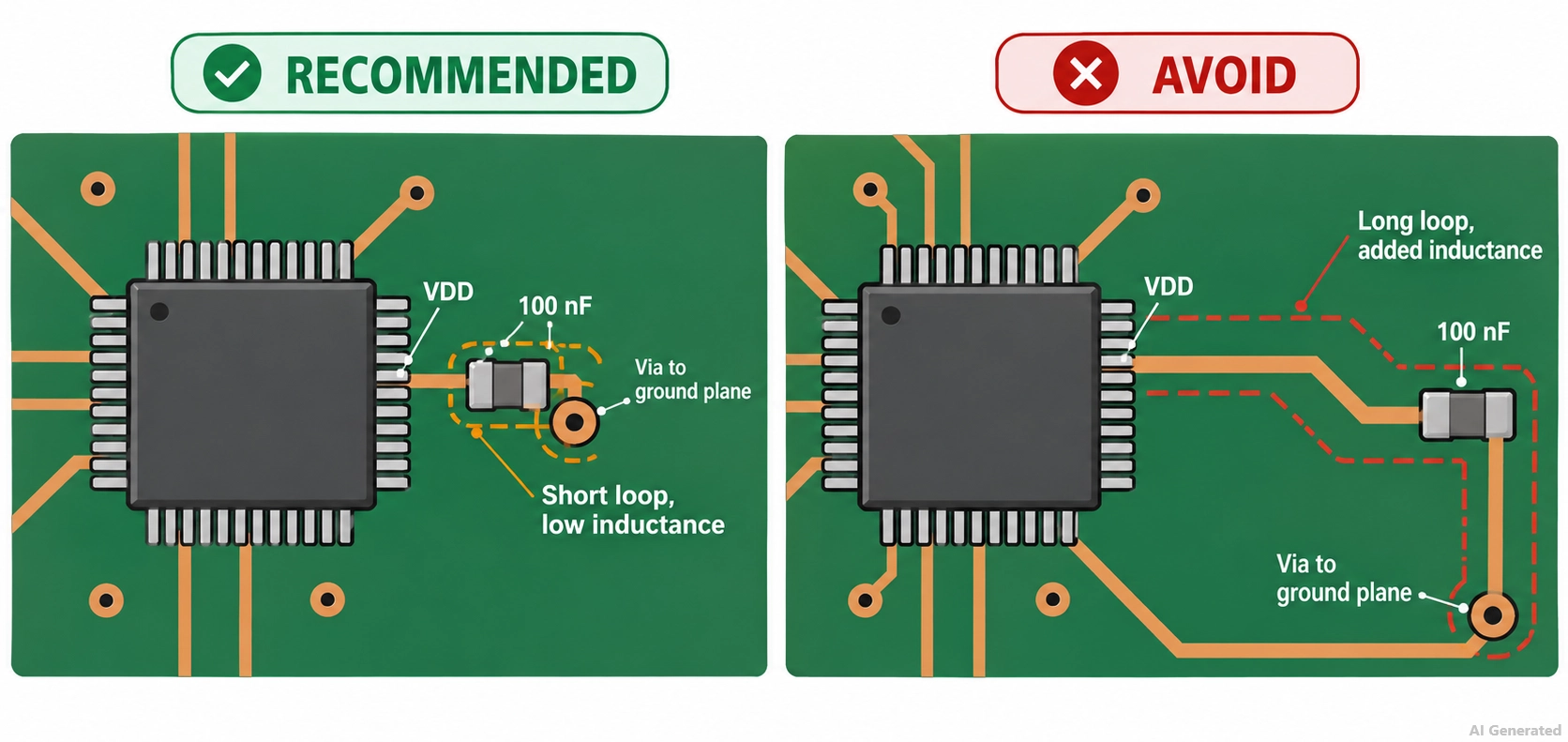
Figure: 100nF decoupling capacitor placed beside an IC power pin with a short via to ground.
Because the impedance of a 100 nF capacitor increases at lower frequencies (15.9 Ω at 100 kHz), designs often pair it with a 1 µF to 10 µF bulk capacitor on the same rail.
Our decoupling capacitor guide covers layout placement and value combinations in detail.
100nF Capacitor Types: Ceramic, Film, and Electrolytic
Most 100 nF capacitors are multilayer ceramic capacitors (MLCCs) because they offer compact size and low ESL for this value. Film capacitors are preferred when stability, low losses, or a mains safety rating is more important
| Type | Polarity | Size at 100nF | Strengths | Typical Use |
|---|---|---|---|---|
| SMD multilayer ceramic (MLCC) | Non-polarized | 0201 to 1206 | Small, low ESL, and low cost | Decoupling, filtering, and general SMT designs |
| Ceramic disc or leaded MLCC | Non-polarized | Through-hole | Easy hand assembly | Breadboards and through-hole boards |
| Polyester (PET) film | Non-polarized | Larger box or dipped body | No DC bias loss, lower distortion than Class 2 ceramic | Audio coupling and general through-hole circuits |
| Polypropylene (PP) film | Non-polarized | Larger than PET | Very low loss and high stability | Snubbers, precision filters, and timing |
| Safety-rated film (X2) | Non-polarized | Large box | Certified for mains connection | Across-the-line EMI filters |
| Aluminum electrolytic or tantalum | Polarized | Larger than an MLCC | Generally not preferred for 100nF applications because MLCCs are typically smaller and have lower ESL | Legacy designs |
How to Choose a 100nF Capacitor
Choosing a 100nF capacitor comes down to four variables: dielectric, voltage rating, package size, and tolerance.
The dielectric and voltage rating matter most because together they determine how much capacitance remains at the operating voltage and temperature.
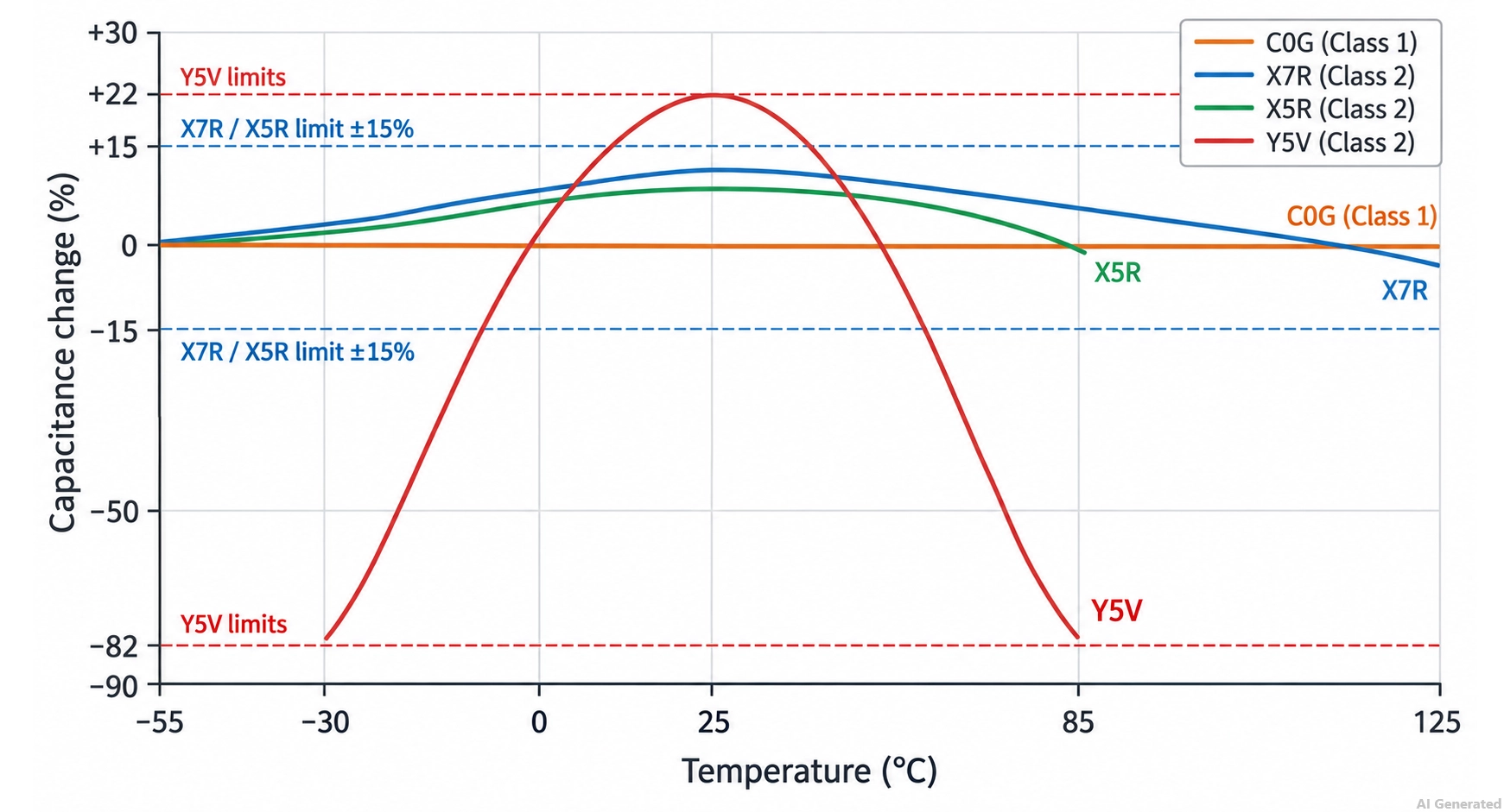
Figure: Capacitance change with temperature for 100nF C0G, X7R, X5R, and Y5V dielectrics.
Dielectric: C0G, X7R, X5R, or Y5V
Ceramic capacitor types include Class 1 and Class 2 dielectrics:
- Class 1 (C0G, also called NP0): Stable over temperature and voltage, with low dielectric losses.
- Class 2 (X7R, X5R, and Y5V): Provides higher capacitance per unit volume, but capacitance varies with temperature, DC voltage, and aging.
| Dielectric | Class | Temperature Range | Temperature Characteristic | Best 100nF Use |
|---|---|---|---|---|
| C0G (NP0) | 1 | −55 to +125 °C | 0 ±30 ppm/°C | Timing, filters, and oscillators |
| X7R | 2 | −55 to +125 °C | ±15% | Decoupling and general use |
| X5R | 2 | −55 to +85 °C | ±15% | Decoupling in small packages |
| Y5V | 2 | −30 to +85 °C | +22% to −82% | Non-critical, cost-driven circuits only |
- Choose X7R for: decoupling and general-purpose use, especially on boards that run warm.
- Choose X5R for: decoupling in 0201 or 0402 packages where the board stays below 85 °C.
- Choose C0G for: RC timing, active filters, and oscillator circuits, where the capacitance sets a time or frequency.
Note
Trade-off: A 100nF C0G capacitor is usually larger and more expensive than an X7R part with the same voltage rating. Y5V is usually the smallest and cheapest option, but its wide capacitance swing makes it a poor fit for supply rails.
Voltage Rating and DC Bias
Choose a voltage rating above the highest voltage the capacitor will see, including transients. Then check how much capacitance a Class 2 part keeps at that voltage.
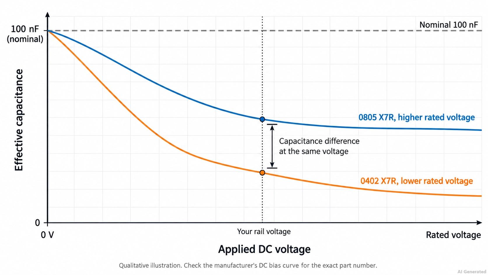
Figure: DC bias reducing the effective capacitance of 100nF X7R capacitors in 0402 and 0805 packages.
X7R and X5R capacitors lose capacitance as the DC voltage across them increases. The loss is typically larger in smaller packages and in parts with a lower rated voltage, so a 100nF 0402 capacitor on a 5 V rail may deliver noticeably less than 100nF.
| Rail Voltage | Common 100nF Voltage Rating |
|---|---|
| 1.8 V to 3.3 V | 10 V or 16 V |
| 5 V | 16 V or 25 V |
| 12 V | 25 V or 50 V |
| 24 V | 50 V |
| 48 V | 100 V |
Selection rule: Read the manufacturer's DC bias curve for the exact part number, and choose the voltage rating or package that keeps enough capacitance at your rail voltage. Most major MLCC manufacturers publish these curves in online selection tools.
Package Size
The package sets the board area, the available voltage ratings, and part of the capacitor's ESL. 0402 and 0603 are the most common choices for 100nF decoupling on SMT boards.
| Package (Imperial and Metric Code) | Nominal Size | Commonly Available 100nF Ratings | Typical Use |
|---|---|---|---|
| 0201 (0603 metric) | 0.6 × 0.3 mm | 6.3 V to 16 V | Dense BGA fanout, wearables, and phones |
| 0402 (1005 metric) | 1.0 × 0.5 mm | 10 V to 50 V | Most compact digital boards |
| 0603 (1608 metric) | 1.6 × 0.8 mm | 16 V to 100 V | General SMT designs are easier to rework |
| 0805 (2012 metric) | 2.0 × 1.25 mm | 16 V to 100 V | Higher voltage with lower DC bias loss |
| 1206 (3216 metric) | 3.2 × 1.6 mm | 50 V to 250 V | Higher-voltage rails and snubbers |
Exact ranges vary by manufacturer, so confirm the rating in the part datasheet. Our guide to SMD capacitor sizes lists the body dimensions for each package.
Trade-off: A smaller package saves area and can sit closer to the power pin, but it typically offers lower voltage ratings and a larger DC bias loss.
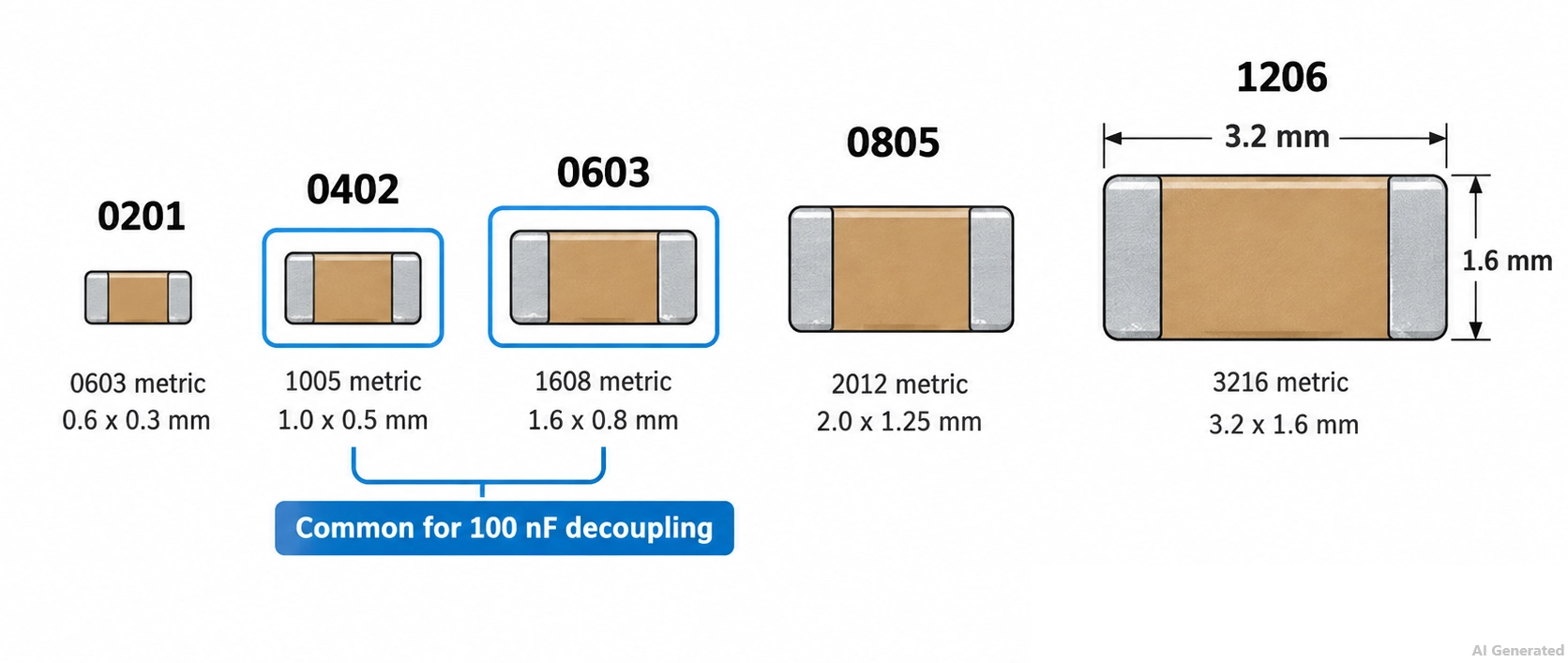
Figure: 100nF MLCC package sizes from 0201 to 1206 shown at the same scale.
Tolerance
Tolerance matters mainly where the capacitance sets a frequency or time.
- Choose ±10% (K) or ±20% (M) for: decoupling, usually in X7R or X5R.
- Choose ±5% (J) or tighter for: RC timing and filters, usually in C0G or film.
Can You Replace a 100nF Capacitor with a Different Value?
Whether you can replace a 100nF capacitor depends on its function in the circuit. In decoupling, the IC datasheet's recommended value comes first.
In timing, filter, and coupling circuits, the value sets a time constant or frequency, so a change needs a new calculation.
| Situation | Replacement |
|---|---|
| Decoupling at an IC power pin | Keep 100nF unless the IC datasheet specifies otherwise; adding 1 µF to 10 µF in parallel for bulk is common |
| RC timing, reset delay, or debounce | Same value; a different value changes the delay in proportion |
| RC or LC filter | Same value, or recalculate the corner frequency |
| AC coupling | A larger value lowers the cutoff frequency; a smaller one raises it |
| Same value, higher voltage rating | Acceptable if it fits the footprint; it often reduces DC bias loss |
| Same value, different dielectric | Only if the circuit tolerates the new temperature and DC bias behavior |
| Mains EMI filter position | Only a part of the same safety class (X for line-to-line, Y for line-to-ground) with an equal or higher voltage rating |
100nF Capacitors in JLCPCB PCB Assembly
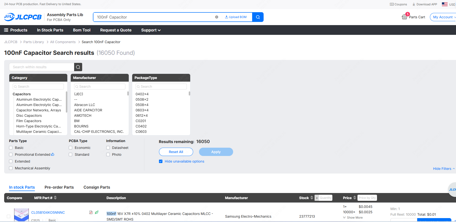
JLCPCB SMT assembly supports passive packages down to 01005 for Standard PCBA and 0402 for Economic PCBA, which covers the usual 100nF decoupling sizes.
The JLCPCB Parts Library lists common 100nF ceramic capacitors. For example, C14663 is a 0603, 50 V, X7R part (YAGEO CC0603KRX7R9BB104) listed as a Basic part.
Before finalizing your BOM, confirm that each part number matches the dielectric, voltage rating, and package your design needs, not only the 100nF value.
Conclusion
A 100nF capacitor is a 0.1 µF capacitor, usually marked 104 on leaded parts, and its main role is local decoupling at IC power pins. For most boards, an X7R or X5R MLCC in 0402 or 0603 is the right starting point, while C0G or film suits circuits where the value sets a time or frequency.
Choosing the dielectric, voltage rating, and package together keeps the effective capacitance at your operating voltage close to the value on the schematic. Once your design is ready, upload your files to JLCPCB to review assembly options and get an instant quote.
FAQs About the 100nF Capacitor
Is 100nF the Same as 0.1 µF?
Yes. 100nF, 0.1 µF, and 100,000 pF are the same capacitance written in different units, and the three-digit code for this value is 104.
What Does 104 Mean on a Capacitor?
It means 100,000 pF, or 100nF. The first two digits give 10, and the third digit adds four zeros, resulting in picofarads.
Does a 100nF Capacitor Have Polarity?
Usually not. Ceramic and film 100nF parts are non-polarized and can be fitted either way, while the uncommon electrolytic and tantalum versions are polarized.
Can I Use a 1 µF Capacitor Instead of 100nF?
Only in some circuits. For decoupling, a 1 µF MLCC often works if the IC datasheet allows it, but in timing, filtering, and coupling circuits, it changes the time constant or cutoff frequency.
Why Do Circuits Pair 100nF with a 10 µF Capacitor?
The 100 nF part handles higher-frequency noise near the IC, while the 10 µF part supplies charge at lower frequencies. Together, they keep the supply impedance low over a wider frequency range.
Popular Articles
• SMD Resistor Package Sizes: Complete Size Chart, Footprints & How to Choose
• How to Solder SMD Components Like a Pro [2026 Updated]
• SMD Resistor Codes: How to Read 3-Digit, 4-Digit, and EIA-96 Markings
• SMD Capacitor Codes: Identification, Markings, and Polarity
• SMD Capacitor Sizes: Complete Size Chart and Selection Tips for PCB Design and Assembly
Keep Learning
ESP8266 vs ESP32: Which One Should You Use?
Key Takeaways ESP32: Dual-core 240 MHz CPU, Bluetooth Classic and BLE, 520 KB SRAM, and up to 34 GPIOs. ESP8266: Single-core CPU, no Bluetooth, and around 50 KB of free RAM for applications. Lifecycle status: Espressif marks the ESP8266 Not Recommended for New Designs (NRND) and names the ESP32-C2 (ESP8684) as its upgrade, although the ESP8266 remains in production with a longevity commitment. Which ESP32 to use: Choose the ESP32-C2 for simple Wi-Fi or Bluetooth LE firmware, the ESP32-C3 for more memo......
What Is a Thermistor? A Practical Guide to NTC, PTC, Applications, and Circuit Design
Key Takeaways Definition: A thermistor is a thermally sensitive resistor whose resistance changes markedly and predictably with temperature, typically by about 4.4% per °C for a standard 10 kΩ NTC (B25/50 = 3950 K) near 25 °C. NTC vs. PTC: An NTC thermistor's resistance falls as temperature rises, which suits temperature sensing and inrush current limiting; a switching PTC's resistance rises steeply above its switch temperature, which suits circuit protection. Key Specifications: An NTC thermistor is ......
What Is the ESP32-CAM, and How to Wire, Power, and Program It?
Key Takeaways Board, not chip: The ESP32-CAM is an AI-Thinker development board, not an Espressif product. It carries AI-Thinker's ESP32-S module, an OV2640 camera, PSRAM, a microSD slot, and a flash LED. No USB port: The board has no USB connector or USB-to-UART bridge, so you program it via its serial pins using a 3.3 V USB-to-serial adapter, with GPIO0 held low at reset. Few free pins: The camera, PSRAM, and microSD card occupy most GPIOs. With the microSD card unused, GPIO2, GPIO4, GPIO12, GPIO13,......
ESP32 Versions: Which One Should You Use for Your Project?
Key Takeaways Radios decide first: ESP32 versions differ mainly in their radios, CPU cores, and peripherals. Common defaults: The ESP32-C3 suits low-cost Wi-Fi and Bluetooth LE, the ESP32-S3 suits camera, display, voice, and on-device AI. Original ESP32: The chip is still in production and remains the choice for Bluetooth Classic. Versions without Wi-Fi: The ESP32-H2 targets battery-powered Thread and Zigbee devices. Chip, module, or board: Prototype on a development board, then design a module onto y......
SOIC Package: A Complete Guide to Specifications, Types, Uses, and SMT Assembly
As designs transition from legacy through-hole components to high-density Surface Mount Technology (SMT), the Small Outline Integrated Circuit (SOIC) remains the industry standard for operational amplifiers, flash memory, sensors, and microcontrollers. It reflects a well-balanced engineering design, offering a practical compromise between the miniaturisation demanded by modern consumer electronics and the ruggedness required for industrial applications. In this guide, you will learn: SOIC package dime......
What Is a 100nF Capacitor and How Do You Choose the Right One
Key Takeaways Value: A 100nF capacitor has a nominal capacitance of 0.1 µF, or 100,000 pF, and all three names describe the same part value. Marking: Many through-hole ceramic and film capacitors use the three-digit code 104, while most SMD MLCCs are unmarked. Main use: Its most common function is local decoupling at an IC power pin, where it supplies fast transient current and shunts high-frequency noise to ground. Default choice: For general decoupling, an X7R or X5R MLCC is a common starting point;......