
Ceramic Capacitor Types Explained: C0G, X7R, X5R, Y5V and How to Choose
15 min
- What Are Ceramic Capacitors?
- SMD MLCC vs Through-Hole Ceramic Capacitor
- Ceramic Capacitor Classes Explained
- Common Ceramic Capacitor Types
- How to Choose the Right Ceramic Capacitor Type
- X7R vs X5R vs C0G: Which Dielectric to Pick
- The DC Bias Effect in Ceramic Capacitor
- Ceramic Capacitor Aging and Piezoelectric Effects
- Understanding Ceramic Capacitor Dielectric Codes
- FAQs about Ceramic Capacitor
- Conclusion
Two ceramic capacitors can share the same capacitance value, the same voltage rating, and the same footprint, yet behave nothing alike on a powered board. The reason is the dielectric, not the number on the label. Ceramic capacitor types are defined by the dielectric, captured in codes like C0G, X7R, X5R, and Y5V.
This guide decodes those codes, compares the dielectric classes, explains the DC bias and aging effects that catch designers off guard, and gives you a practical way to pick the right part for each job.
What Are Ceramic Capacitors?
A ceramic capacitor uses a ceramic material as its dielectric, sandwiched between metal electrodes. They are non-polarized, so capacitor polarity is not a concern on the board, and they offer very low equivalent series resistance (ESR) and equivalent series inductance (ESL), which is exactly why they dominate high-frequency decoupling.
Multilayer ceramic capacitors, or MLCCs, are the most produced and most used capacitors in modern electronics, with annual production measured in the trillions of pieces. They stack dozens to hundreds of thin dielectric layers in parallel inside a single chip, which is how a part the size of a grain of rice reaches into the microfarad range.
"Ceramic capacitor types" can mean two things: construction (an SMD MLCC versus a through-hole leaded part) or the dielectric class and code (C0G versus X7R). Both matter, and this guide covers both, starting with construction.
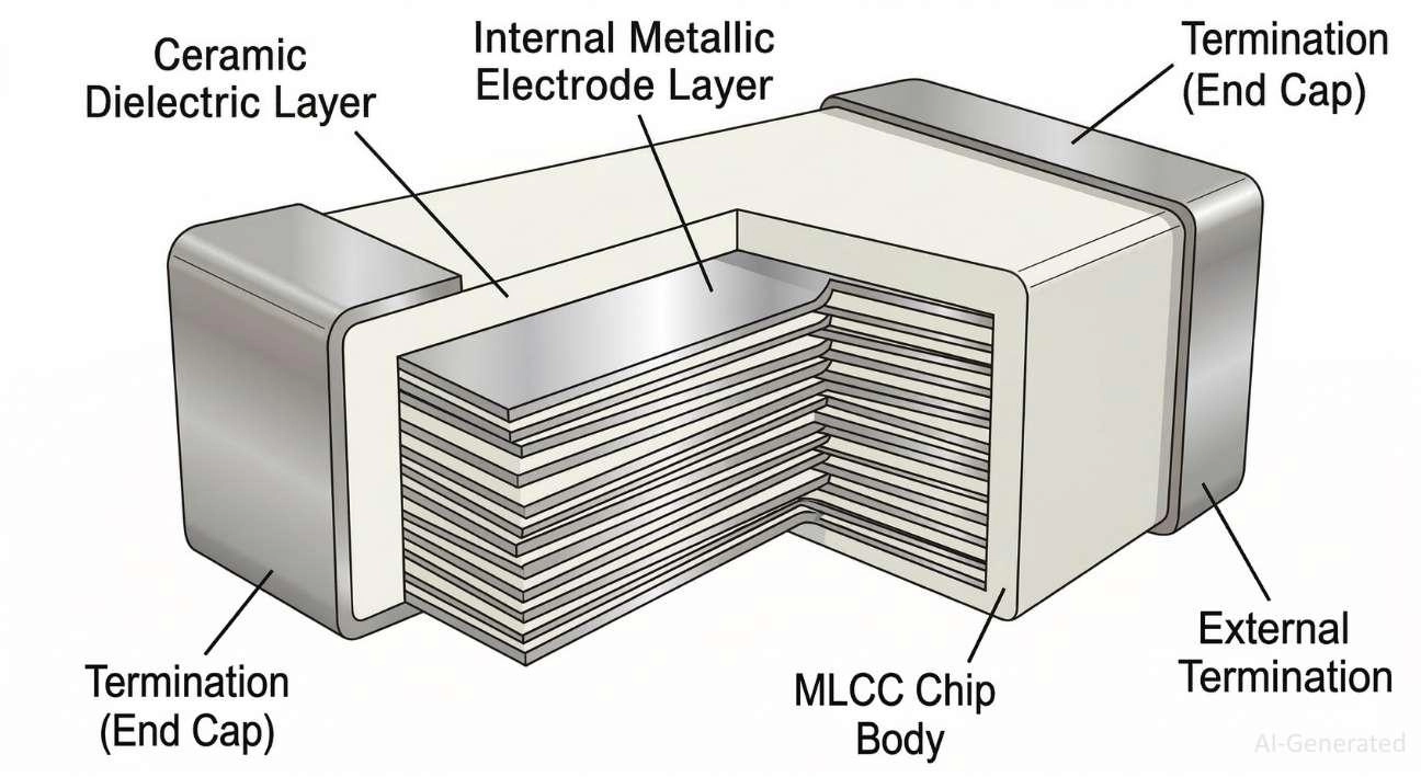
Figure: A multilayer ceramic capacitor showing stacked ceramic dielectric layers and interleaved metal electrodes connecting to opposite end terminations.
SMD MLCC vs Through-Hole Ceramic Capacitor
Ceramic capacitors come in a few physical forms, but two cover the vast majority of designs. Choosing between them often comes down to an evaluation of surface-mount vs through-hole constraints for your board layout.
SMD MLCC
The surface-mount MLCC is the workhorse of modern electronics. It packs high capacitance density into compact chip packages (0402, 0603, 0805 and up) and handles high frequencies exceptionally well. If a board has bypass and decoupling capacitors, they are almost certainly SMT MLCCs.
Through-Hole (THT) and Specialty Ceramic Capacitor
Through-hole ceramic capacitors trade small physical size for mechanical durability and high-voltage handling:
- Ceramic Disc Capacitors: The classic orange-brown leaded disc is a single-layer through-hole part. Highly resilient under high voltage, it remains a staple in AC power supplies, EMI suppression, and safety-rated (Class X/Y) line filtering.
- Radial Leaded MLCCs: Standard MLCC blocks fitted with wire leads and protective epoxy, bringing high capacitance density to through-hole footprints.
- Specialty Types: Feedthrough capacitors for panel-mount signal filtering and high-voltage "doorknob" ceramic capacitors for high-power RF systems.
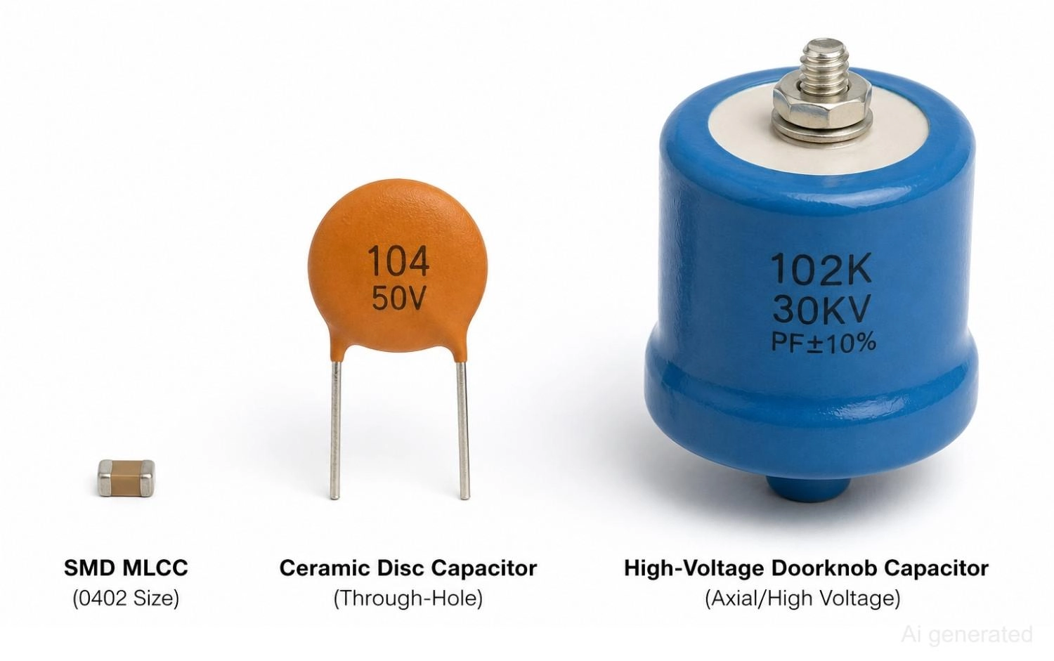
Figure: Comparison of an SMD multilayer ceramic capacitor, a through-hole ceramic disc capacitor, and a high-voltage ceramic doorknob capacitor.
Ceramic Capacitor Classes Explained
When engineers say "ceramic capacitor types," they usually mean the dielectric classes defined by stability. The classes trade stability against density: the more stable the dielectric, the less capacitance you get in a given size.
- Class 1 dielectrics are paraelectric. They deliver excellent stability, very low loss, and essentially no aging, but only modest capacitance density, so values stay small (picofarads to low nanofarads). C0G (NP0) is the dominant Class 1 dielectric.
- Class 2 dielectrics are ferroelectric, based on barium titanate. They pack far more capacitance into the same volume, which is how you get microfarads in a tiny chip, but they drift with temperature and voltage, age over time, and can be microphonic. X7R and X5R are the workhorses.
- Class 3 dielectrics are high-K barrier-layer types with the highest density and the worst stability of all. They are largely obsolete in modern SMD design. Y5V and Z5U are the familiar examples.
A note on standards
Classification differs between authorities. Under EIA RS-198, Y5V and Z5U are grouped as Class 2 high-K dielectrics. Under IEC 60384 and in many published articles, the same materials are called Class 3. The materials and behavior are identical; only the label changes.
| Class | Dielectric Type | Stability | Capacitance Density | Common Codes | Typical Applications |
|---|---|---|---|---|---|
| Class 1 | Paraelectric | Excellent | Low | C0G, NP0 | RF, timing, precision analog |
| Class 2 | Ferroelectric | Good | High | X7R, X5R, X8R | Decoupling, bypass, bulk |
| Class 3 | High-K ferroelectric | Poor | Very high | Y5V, Z5U | Non-critical bulk, legacy |
Common Ceramic Capacitor Types
With the codes decoded, here is how the dielectrics you will actually specify behave in practice.
C0G (NP0) Capacitors
A Class 1 dielectric with near-zero temperature drift, no measurable aging, and a negligible DC bias effect. It is also free of microphonics. The trade-off is low capacitance density, so values run from picofarads up to the low nanofarads.
- Use for: RF circuits, oscillators, resonators, filters, precision analog, and timing.
- Avoid for: High-capacitance bulk storage and decoupling, where the value is not physically available.
X7R Capacitors
The general-purpose default. X7R covers -55°C to +125°C with ±15% change, balances stability against density well, and reaches into the microfarad range. Among all MLCC dielectric types, X7R remains the most widely used choice for general-purpose decoupling. It is the standard choice when implementing a bypass capacitor in PCB layouts for decoupling and power-rail bypass applications. Be aware that it is subject to DC bias loss and aging.
- Use for: General-purpose decoupling, bypass, and power-rail filtering on most PCBs.
X5R Capacitors
Closely related to X7R, with the same ±15% tolerance but a reduced upper temperature limit of +85°C. The relaxed temperature spec lets manufacturers pack more capacitance into a smaller case, so X5R wins in space-constrained consumer and mobile designs where the board never gets too hot.
- Use for: Compact consumer electronics and mobile devices with moderate operating temperatures.
X6S, X7S, and X8R Capacitors
Newer Class 2 formulations aimed at automotive and industrial use. They push either a wider temperature range or tighter behavior at temperature. X7S holds ±22% from -55°C to +125°C, and X8R extends the upper limit to +150°C. Look for AEC-Q200 qualified parts in these families for automotive work.
- Use for: Automotive, industrial, and high-temperature environments.
Y5V Capacitors
The high-K extreme: enormous capacitance density in a tiny package, with severe stability penalties. A Y5V part can swing from +22% to -82% across its -30°C to +85°C range, and it is highly sensitive to DC bias. Treat the marked value as a loose upper bound, not a guarantee.
- Use for: Cost-sensitive, non-critical bulk storage where the exact value does not matter.
Z5U Capacitors
A legacy high-K dielectric with a narrow +10°C to +85°C range and poor stability. It still turns up in older designs but is being displaced by better Class 2 parts.
Common Ceramic Dielectrics at a Glance
| Dielectric | Best Use | Stability | DC Bias Sensitivity | Temperature Range |
|---|---|---|---|---|
| C0G / NP0 | RF, timing, precision | Excellent | Very low | -55°C to +125°C |
| X7R | General decoupling | Good | Moderate | -55°C to +125°C |
| X5R | Compact electronics | Good | Moderate | -55°C to +85°C |
| X7S | Automotive, industrial | Moderate | Moderate | -55°C to +125°C |
| Y5V | Non-critical bulk | Poor | High | -30°C to +85°C |
| Z5U | Legacy circuits | Poor | High | +10°C to +85°C |
How to Choose the Right Ceramic Capacitor Type
After enough board bring-ups, dielectric selection becomes a quick mental checklist rather than a datasheet hunt.
In our own designs, we default to X7R for nearly all MCU and digital decoupling, and only switch to C0G when the capacitance directly sets a frequency, a timing constant, or an analog precision spec. When space is the binding constraint and the board runs cool, we drop to X5R for the density. Here is the rest of the workflow:
- For RF and Oscillator Circuits: Reach for C0G (NP0). When the capacitance value sets a frequency or a filter corner, you need zero drift and no bias dependence. Nothing else qualifies.
- For Decoupling and Power Rails: Default to X7R. It gives microfarads of stable bypass across full industrial temperature, and after voltage derating, it holds up well under bias. This covers the vast majority of digital decoupling.
- For Compact Consumer Devices: Use X5R when the board temperature stays under +85°C and you need maximum capacitance in the smallest case. It is the mobile and consumer staple.
- For High-Temperature and Automotive Applications: Specify X7R, X7S, or X8R, and insist on AEC-Q200 qualified parts for anything under the hood or in an engine bay.
- For Non-Critical Bulk Storage: Y5V is acceptable only when the value truly does not matter and cost rules. Size it generously, because what you mark is not what you get.
The single rule that ties it together: pull the DC bias and temperature curves for the actual part number before you lock the BOM. The marked value is a starting point, not a promise.
Recommended Ceramic Capacitor Types by Application
| Application | Recommended Dielectric |
|---|---|
| RF circuits | C0G (NP0) |
| Oscillators and timing | C0G (NP0) |
| Precision analog | C0G (NP0) |
| MCU and digital decoupling | X7R |
| Power supply bypass | X7R |
| Smartphones and wearables | X5R |
| Automotive and high-temp | X7R / X8R |
| Non-critical bulk storage | Y5V |
When your design is ready to build, you can source both SMD dielectrics and through-hole leaded package options through the extensive JLCPCB Parts Library. Sourcing your parts and fabricating your PCBs through the same ecosystem ensures that the components you carefully specified are the exact ones that land on the final assembly.
X7R vs X5R vs C0G: Which Dielectric to Pick
Quick Answer: For most PCB designs, X7R is the best default choice. Use C0G when capacitance stability is critical, and X5R when maximum capacitance density matters more than temperature range.
These three dielectrics cover the large majority of real designs, and most "ceramic capacitor type" searches are really asking how they differ. Here they are head to head.
X7R vs X5R vs C0G Comparison
| Property | C0G (NP0) | X7R | X5R |
|---|---|---|---|
| Class | 1 | 2 | 2 |
| Stability | Excellent | Good | Good |
| Temp range | -55°C to +125°C | -55°C to +125°C | -55°C to +85°C |
| DC bias | Minimal | Moderate | Moderate (higher in small cases) |
| Aging | None | Logarithmic | Logarithmic |
| Max capacitance | Low | High | Very high |
| Best use | RF, timing | General decoupling | Compact decoupling |
Key Takeaway
Pick C0G when the value must not move, X7R when you need stable bulk decoupling across full industrial temperature, and X5R when you need maximum capacitance in the smallest case, and the board stays under +85°C.
If you are unsure which dielectric to choose, start with X7R. Move to C0G when stability matters, or X5R when board space is critical.
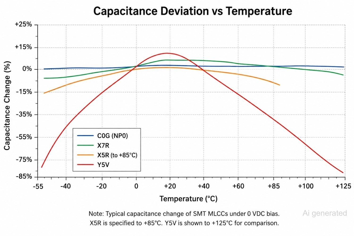
Figure: Comparing capacitance deviation versus temperature for C0G, X7R, X5R, and Y5V ceramic dielectrics, showing C0G nearly flat and Y5V swinging dramatically.
The DC Bias Effect in Ceramic Capacitor
Why a 10 uF Capacitor May Not Be 10 uF
This is the trap that catches engineers who size capacitance from the marked value alone. Class 2 and Class 3 ceramics are ferroelectric, and applying a DC voltage polarizes the dielectric and saturates its domains. As bias rises, effective capacitance falls, often dramatically. The marked value is measured at near-zero volts, not at your operating voltage.
The effect is worse in the high-K dielectrics. A Y5V capacitor operated at only half its rated voltage can lose roughly 30% to 50% of its nominal capacitance from DC bias alone. Stack temperature drift and aging on top, and a part marked 10 uF can deliver well under half that in circuit, with worst cases falling below a few microfarads. X7R and X5R behave far better than Y5V, but they are not immune, and the loss grows steeply in smaller case sizes that cram more capacitance into less volume.
A capacitor labeled 10 uF should be treated as a starting value, not the guaranteed value under operating conditions.
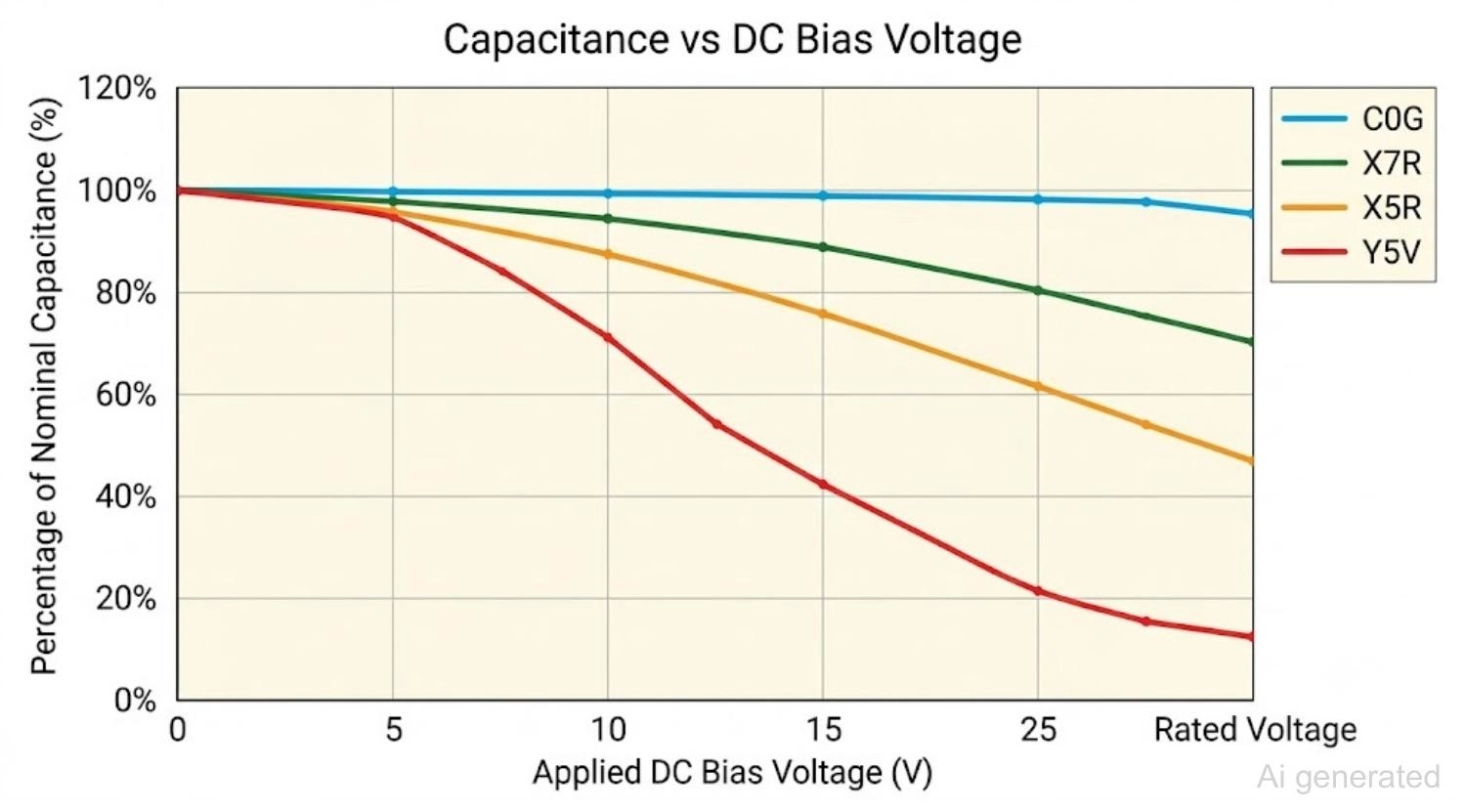
Figure: Showing effective capacitance staying flat for C0G but dropping sharply for X7R, X5R, and especially Y5V as DC bias voltage increases toward the rated voltage.
Designer Tips
- Derate voltage aggressively: Choosing a part with a rated voltage around twice your operating voltage keeps you on the flatter, more predictable part of the bias curve.
- Verify parameters via manufacturer tools: Always check the manufacturer DC bias curve, not just the headline value. Tools like Murata SimSurfing and KEMET K-SIM plot effective capacitance versus bias for the exact part number.
- Adjust layout dimensions if necessary: Move up a case size or parallel multiple parts when the capacitance must hold under bias.
Ceramic Capacitor Aging and Piezoelectric Effects
Ceramic Capacitor Aging Characteristics
Class 2 and Class 3 dielectrics lose capacitance over time as the barium titanate crystal structure relaxes. The loss is logarithmic, expressed as a percentage per decade-hour (per 10x increase in time). Typical published rates are about 2% to 2.5% per decade-hour for X7R and X5R and around 7% per decade-hour for Y5V, so a Y5V part can shed roughly a third of its capacitance over years. C0G, being paraelectric, does not age this way. Aging resets when a part is heated above its Curie point - for example, during the SMT reflow phase - so the clock effectively starts at assembly.
Ceramic Capacitor Piezoelectric Effect and Microphonics
Class 2 and Class 3 ceramics are mildly piezoelectric. Mechanical vibration generates a small voltage, and conversely, an AC voltage makes the part physically flex. On a board carrying audio-band signals, this shows up as audible noise, the so-called "singing capacitor." Where it matters, in audio paths and sensitive analog front ends, reach for C0G, which is immune, or apply layout and mounting mitigations.
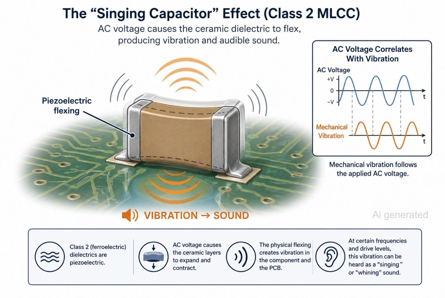
Figure: Showing piezoelectric flexing of a Class 2 ceramic capacitor on a PCB radiating sound, the singing capacitor effect.
Understanding Ceramic Capacitor Dielectric Codes
The cryptic three-character codes are not random. They encode the operating temperature range and the capacitance stability. Class 1 and Class 2/3 use two different coding systems, which trip up many references.
Class 2 and Class 3 EIA Code
For Class 2 and Class 3 parts, the format is letter, number, letter:
- First letter = lowest operating temperature
- Second number = highest operating temperature
- Third letter = maximum capacitance change across that range
EIA Code Decoder for Class 2 and Class 3 Capacitors
| Low-Temp Letter | High-Temp Number | Capacitance-Change Letter |
|---|---|---|
| Z = +10°C | 2 = +45°C | A = ±1.0% |
| Y = -30°C | 4 = +65°C | B = ±1.5% |
| X = -55°C | 5 = +85°C | C = ±2.2% |
| 6 = +105°C | D = ±3.3% | |
| 7 = +125°C | E = ±4.7% | |
| 8 = +150°C | F = ±7.5% | |
| 9 = +200°C | P = ±10% | |
| R = ±15% | ||
| S = ±22% | ||
| T = +22 / -33% | ||
| U = +22 / -56% | ||
| V = +22 / -82% |
Example: Decoding X7R and X5R
X7R decodes to X (-55°C) low, 7 (+125°C) high, R (±15%). So an X7R capacitor operates from -55°C to +125°C with no more than ±15% capacitance change.
Decode X5R the same way, and you get -55°C to +85°C, ±15%. The only difference between the two is the upper temperature limit. A separate numeric marking such as 104 gives the value in picofarads;
Check our detailed tutorial on how to read SMD capacitor code designations for a complete breakdown of the marking systems.
Class 1 Ceramic Capacitor Codes (C0G and NP0)
Class 1 uses a different scheme based on the temperature coefficient in parts per million per degree C (ppm/°C).
For practical purposes, all you need is the result: C0G is 0 ±30 ppm/°C, which is less than ±0.3% change from -55°C to +125°C, with negligible hysteresis. (For the curious: the first character is the coefficient's significant figure, the middle digit a multiplier, the final character the ppm/°C tolerance.)
Accuracy Note:
C0G is the modern EIA designation, and NP0 (negative-positive-zero) is the older name for the same dielectric. They are identical. Some guides reverse this; they are wrong. The IEC 60384 equivalent is CG.
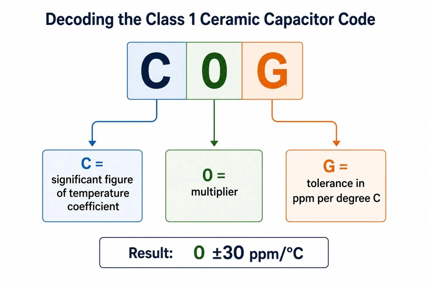
Figure: Decoding the Class 1 ceramic capacitor code C0G into its temperature-coefficient significant figure, multiplier, and tolerance, resulting in 0 plus or minus 30 ppm per degree C.
FAQs about Ceramic Capacitor
Q: Are ceramic capacitors polarized?
No. Ceramic capacitors are completely non-polarized. Unlike tantalum or aluminum electrolytic capacitors, which will fail catastrophically if installed backward, ceramic capacitors have symmetric metal electrodes and can be placed in either physical orientation on a PCB without issue.
Q: What is the most common ceramic capacitor type?
The Class 2 X7R MLCC is the most widely used ceramic capacitor in modern electronics. It offers the best practical balance between capacitance density, temperature stability, cost, and overall performance for general-purpose decoupling.
Q: What is the difference between X7R and X5R?
The primary difference is the maximum operating temperature rating. X7R is rated up to +125°C, while X5R is limited to +85°C. Because of this relaxed limit, X5R can achieve higher capacitance density in smaller packages (like 0201 or 0402).
Q: Why does my 10 uF ceramic capacitor measure much lower in circuit?
This is due to the DC bias effect. Class 2 and Class 3 ceramics are ferroelectric; applying a DC voltage polarizes the material and reduces its ability to respond to AC signals, resulting in a dramatic drop in effective capacitance at operating voltage.
Conclusion
The dielectric on a ceramic capacitor defines its real-world performance far more than the nominal value. Use Class 1 C0G for precision, Class 2 X7R/X5R for standard decoupling, and always account for DC bias and aging.
When your design is ready for production, JLCPCB's PCB assembly service helps ensure the capacitors you specify are the ones assembled onto the final board. You can instantly source components from the JLCPCB Parts Library and check project costs using the online quotation tool.
Popular Articles
• SMD Diode Code Lookup: Full List, Marking Guide & Identification [2026 Guide]
• SMD Resistor Package Sizes: Complete Size Chart, Footprints & How to Choose
• SMD Capacitor Codes: Identification, Markings, and Polarity
• SMD Capacitor Sizes: Complete Size Chart and Selection Tips for PCB Design and Assembly
• How to Solder SMD Components Like a Pro [2026 Updated]
Keep Learning
PoP Package (Package on Package) Explained: Architecture, Assembly, and SMT Challenges
In the race for miniaturization, fitting more processing power into smaller footprints is the ultimate challenge for PCB designers. Package on Package (PoP) technology answers this by integrating logic and memory vertically, becoming the standard for modern mobile processors. However, this 3D architecture demands advanced SMT assembly capabilities beyond standard fabrication. JLCPCB specializes in the high-precision manufacturing required to master these complex stacks. This guide covers how PoP packa......
What Is a PQFP Package? Plastic Quad Flat Package Design, Footprint, and Assembly Guide
The Plastic Quad Flat Package (PQFP) is a widely used IC package in industrial, automotive, and embedded designs. This article provides a practical, engineering-focused guide to PQFP package. It explains how PQFP is built, when it makes sense to use it, how it compares with newer package types, and what designers should consider in terms of footprint design, thermal performance, signal integrity, manufacturing, and reliability. What Is a PQFP Package (Plastic Quad Flat Package)? A Plastic Quad Flat Pa......
Small Outline Integrated Circuit (SOIC): Package, Specs & Uses
As designs transition from legacy through-hole components to high-density Surface Mount Technology (SMT), the Small Outline Integrated Circuit (SOIC) remains the industry standard for operational amplifiers, flash memory, sensors, and microcontrollers. It stands as a testament to balanced engineering, offering a perfect compromise between the miniaturisation demanded by modern consumer electronics and the ruggedness required for industrial applications. This article serves as a definitive engineering ......
A Complete Guide to Surface Mount Device (SMD)
Imagine holding a smartphone in your hand. Inside that sleek device lies a complex network of thousands of miniature components — resistors smaller than a grain of rice, capacitors thinner than a fingernail, and integrated circuits containing millions of transistors. Without Surface Mount Technology (SMT) and its compact Surface Mount Devices (SMDs), none of this would exist. Just a few decades ago, electronics were bulky. Radios filled desks, computers filled rooms, and assembling a circuit meant dri......
Circuit Breaker Types Explained: MCB, MCCB, RCCB, RCBO, ACB, VCB & SF6 Circuit Breakers
A circuit breaker automatically disconnects power when it detects faults such as overloads or short circuits, protecting equipment and reducing fire risk. Different circuit breaker types are designed for different voltage levels, current ratings, and applications, from household distribution boards to high-voltage substations. This guide explains the most common types - including MCBs, MCCBs, RCCBs, RCBOs, ACBs, VCBs, and SF6 breakers and helps you choose the right one for your application. Figure: Ci......
Quad Flat Package (QFP): The Engineer's Guide to Design, Assembly and Thermal Management
What is QFP Package? The Quad Flat Package (QFP) is one of the most popular surface mount technology (SMT) package formats throughout the history of electronic manufacturing. After it became standard in the 1980s, the QFP has been the industry standard for integrated circuits (ICs) with moderate to high pin counts that typically range from 32 to 304 pins, so it was a good alternative for simple SOIC packages and complex Ball Grid Arrays (BGAs) at the same time. Defined by its "gull-wing" leads extendi......