
SMD Diode Polarity Guide: How to Identify Cathode Marking & Prevent PCB Damage
11 min
- Quick Visual Diode Polarity Examples
- Common SMD Diode Polarity Markings at a Glance
- How to Identify SMD Diode Polarity (Quick Answer)
- What is SMD Diode Polarity?
- Why Correct Diode Polarity is Critical in Electronic Circuits
- Visual Identification of SMD Diode Polarity
- How to Test SMD Diode Polarity Using a Multimeter
- Understanding Diode Polarity in Circuit Schematics
- Common PCB Locations Where Diode Polarity Matters
- Common Mistakes When Identifying Diode Polarity
- Real Repair Scenario: The Dead Power Supply
- How to Install an SMD Diode Correctly on PCB
- FAQ About SMD Diode Polarity
- Conclusion
Installing an SMD diode in the wrong orientation can instantly damage a PCB or prevent a circuit from working. Whether you are assembling a prototype or troubleshooting hardware, understanding SMD diode polarity is a fundamental electronics skill.
In this guide, you will learn:
1. how to visually identify SMD diode polarity markings
2. how to find the anode and cathode direction on different packages
3. how to test diode polarity using a digital multimeter
4. how polarity appears in schematics and PCB layouts
5. common mistakes that lead to circuit failure
Quick Visual Diode Polarity Examples
- SMA/SMB diode: White or silver band indicates cathode.
- SOD-123 diode: Laser-etched line indicates cathode.
- SOT-23 package: Identified by its 3-pin physical layout (Pins 1 & 2 on one side, Pin 3 on the other). Check the datasheet for internal routing.
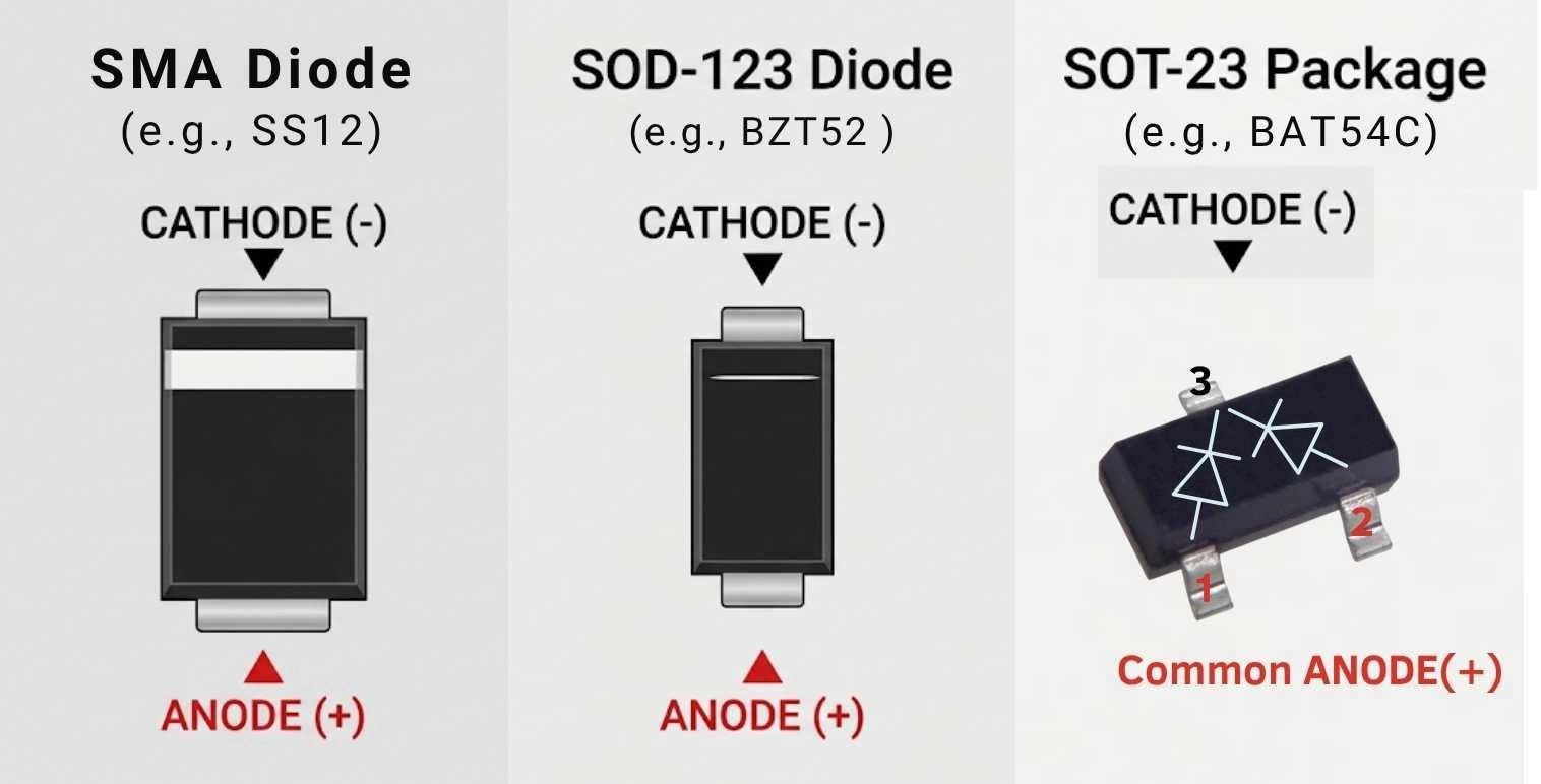
Figure: SMD diode polarity markings, including SMA, SOD-123, and 3-pin SOT-23 packages.
Common SMD Diode Polarity Markings at a Glance
- White band → Cathode (-)
- Laser line → Cathode (-)
- Notch → Cathode (-)
- SOT-23 3-Pin Layout → Relies on datasheet for internal configuration (Common Anode/Cathode/Series)
- No band → Possible bidirectional TVS diode
How to Identify SMD Diode Polarity (Quick Answer)
-
Look for physical marks: Find the cathode band, notch, or laser etching on the component body.
-
Match with schematic: Align the physical mark with the straight vertical line on the diode symbol.
-
Test electrically: Use a multimeter in diode mode to confirm the forward voltage drop.
-
Confirm PCB traces: Trace the pads to ground or main power rails.
-
Verify the datasheet: Always check manufacturer specifications for specific packages before soldering.
What is SMD Diode Polarity?
A diode allows electrical current to flow freely in one direction while blocking it entirely in the opposite direction. This directional nature is known as "polarity."
Every standard diode has two terminals: the Anode (+) and the Cathode (-). For current to flow, the voltage at the anode must be higher than at the cathode (forward-biased state). If reversed (higher at the cathode), the diode blocks the current (reverse-biased state).
Understanding the SMD diode anode-cathode relationship is critical to ensure the component behaves correctly and protects your circuit from reverse voltages.
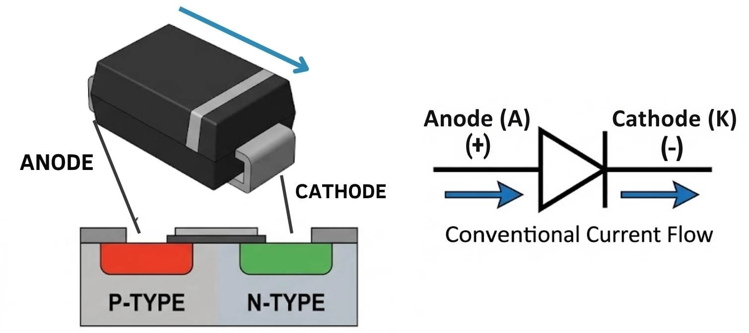
Figure: Diagram explaining the SMD diode anode and cathode structure and the correct direction of current flow.
Why Correct Diode Polarity is Critical in Electronic Circuits
Ignoring or misidentifying diode polarity causes catastrophic hardware failures. Why correct polarity matters:
- Reverse polarity protection failure → IC destruction.
- Flyback diode wrong direction → Transistor burnout.
- Zener reversed → Unstable regulator voltage.
- Battery circuit diode reversed → Discharge or swelling.
- Power rectifier reversed → Heavy current and blown fuses.
Visual Identification of SMD Diode Polarity
Cathode Band Marking Meaning
The most universal standard in the electronics industry for identifying diode polarity is the cathode band. But what is the diode polarity band meaning? Simply put, the physical line or band painted, etched, or molded onto the body of the diode indicates the Cathode (-) terminal.
- White or Silver Band: Common on black epoxy bodies (like SMA or SMB packages), this thick line distinctly marks the cathode end.
- Laser Marking: On modern, ultra-small components, the SMD diode cathode marking might be a very faint, laser-etched line that is only visible under a microscope or tilted in the light.
- Molded Notch: Some specialized or high-power diodes may feature a physical notch or chamfered edge on the cathode side instead of printed ink.
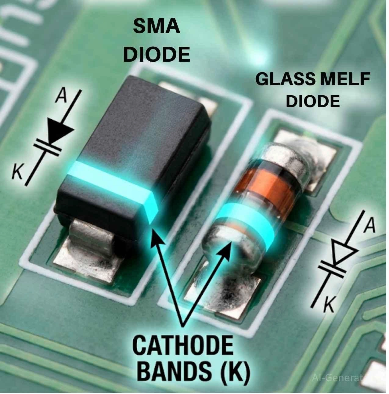
Figure: The standard SMD diode cathode marking and diode polarity band meaning.
Package-Specific Polarity Marking
Different surface mount packages utilize specific marking conventions. Refer to the table below for standard polarity marks:
|
Package Type |
Polarity Mark Style |
Typical Application |
|---|---|---|
|
SOD-123 |
Solid or laser-etched line |
Small signal switching, Zener (sod-123 diode polarity) |
|
SMA / SMB / SMC |
Thick white or silver band |
Power rectification (Schottky diode polarity marking) |
|
SOT-23 |
Pin 3 is usually the cathode (check datasheet) |
Signal clipping, dual-diode arrays |
|
TVS (Transient Voltage Suppressor) |
Unidirectional: Band. Bidirectional: No band |
ESD protection (TVS diode polarity direction) |
|
MiniMELF / LL34 |
Colored ring (black, blue, red) |
Precision signal |
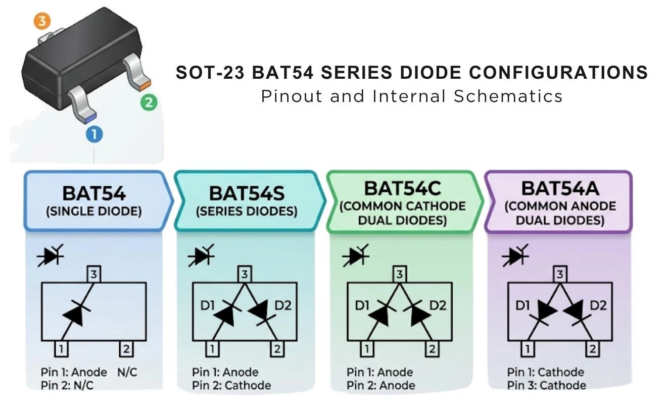
Figure: An SOT-23 package showing the standard asymmetric pin numbering (Pins 1 and 2 on the bottom, Pin 3 on the top) alongside internal schematic variations like the BAT54 series.
When Polarity Marking is Missing or Burnt
During repairs, you will often find diodes that have overheated, burning away their protective epoxy and silkscreen markings. In these cases, visual identification fails. To deduce the diode direction on the PCB, trace the PCB tracks. Look for the ground plane or the main VCC power rail. By analyzing surrounding components and reading the schematic, you can logically determine the anode and cathode pads.
How to Test SMD Diode Polarity Using a Multimeter
When visual markings are ambiguous, worn away, or you simply want to verify a component before soldering, you need to know how to perform a diode polarity test with a multimeter.
Diode Mode Testing Steps
Virtually all modern digital multimeters have a dedicated "Diode Test" function. Here is exactly how to use it:
-
Select Diode Mode: Turn your multimeter dial to the diode symbol (it looks like a triangle pointing at a line).
-
Probe Orientation: Place the Red probe on one side of the SMD diode and the Black probe on the other.
-
Read the Voltage: * If the multimeter displays a voltage drop (typically between 0.2V and 0.7V), you have correctly found the polarity. The Red probe is touching the Anode, and the Black probe is touching the Cathode.
If the multimeter reads "OL" (Open Loop) or "1", the diode is reverse-biased. Swap the probes.
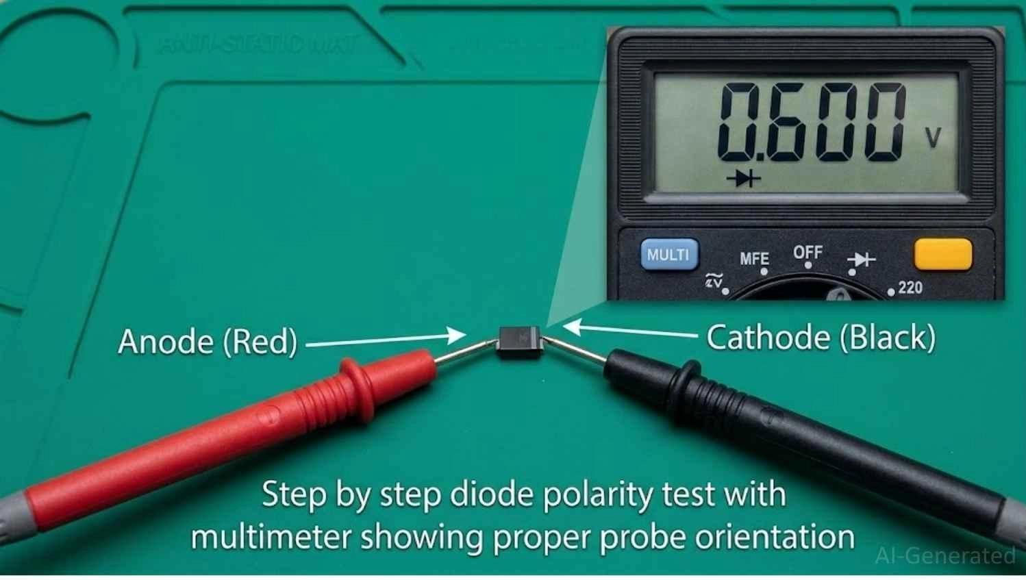
Figure: Diode polarity test with multimeter showing proper probe orientation.
Forward Voltage Interpretation Table
When you successfully measure a diode, the voltage displayed isn't just a random number; it's the diode forward voltage identification. This number helps you verify what type of diode you are testing:
|
Voltage Reading (Vf) |
Diode Type Indicated |
|---|---|
|
0.15V - 0.45V |
Schottky Diode (Low forward voltage drop, high switching speed) |
|
0.60V - 0.75V |
Standard Silicon Rectifier / Small Signal Diode |
|
1.80V - 3.30V |
Light Emitting Diode (LED) - varies by color |
Reverse Bias Leakage Test
To check how to know diode is reverse biased or failing, use resistance mode (Ohms). In reverse bias (Black probe Anode, Red Cathode), a healthy diode shows infinite resistance (OL). Measurable resistance indicates internal "leakage" damage - replace immediately.
Understanding Diode Polarity in Circuit Schematics
Diode Symbol Orientation
- The flat side of the triangle is the Anode (+).
- The straight vertical line is the Cathode (-).
Think of the triangle as an arrowhead pointing in the direction of conventional current flow. The vertical line represents the physical cathode band painted on the real-world component.
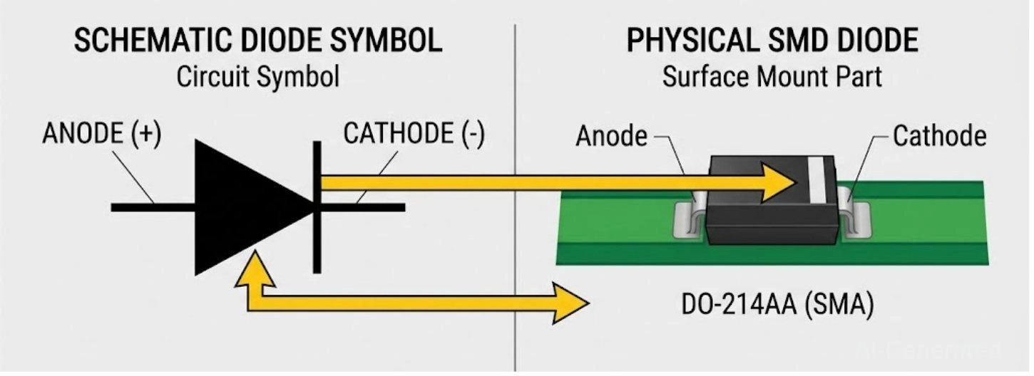
Figure: Comparing SMD diode symbol polarity to real-world surface mount diode orientation.
Tracing Polarity on PCB Tracks
Proper solder pad design uses a thick silkscreen line or a squared pad for the cathode. If the silkscreen is missing, determine the diode direction on the PCB by tracing the tracks:
-
Identify ground pad continuity: Use a multimeter to locate the ground plane.
-
Follow the track to the connector/regulator: Trace the pad back to the main power source.
-
Confirm direction using schematic: Verify if the nearby IC requires an input or dumps to ground.
Common PCB Locations Where Diode Polarity Matters
If you are learning how to test an SMD diode on a PCB, knowing where to look speeds up troubleshooting immensely.
|
Circuit Location |
Diode Function |
Polarity Role |
|---|---|---|
|
DC Power Input |
Reverse Polarity Protection |
Block the current if the user plugs in a power supply backward. |
|
Relay / Motor Driver |
Flyback (Freewheeling) Diode |
Placed in reverse bias across a coil to absorb destructive voltage spikes when the magnetic field collapses. |
|
USB / Data Ports |
ESD Protection (TVS) |
Shunts high-voltage static shocks directly to ground before they reach the CPU. |
|
Switching Power Supply |
Output Rectification |
Converts high-frequency AC switching signals back into smooth DC power. |
Common Mistakes When Identifying Diode Polarity
Even experienced technicians make errors during high-speed assembly or late-night repairs. Avoid these pitfalls:
- Reading the Band Upside Down: On some cylindrical MELF packages, a manufacturer might print multiple color bands. Always look for the thickest band, or the one closest to the absolute edge of the glass - that is the cathode.
- Confusing with Resistors: Zero-ohm SMD jumpers or precise MELF resistors can sometimes look identical to glass diodes. Always verify with a multimeter.
- Wrong Schematic Reading: Assuming a Zener diode is placed forward-biased. Zener diodes are almost exclusively placed in reverse bias to utilize their breakdown voltage for regulation.
- Dual Diode Confusion: In SOT-23 packages containing two diodes, guessing the common anode/cathode pin without the datasheet often results in dead shorts.
Real Repair Scenario: The Dead Power Supply
Let's look at a practical example of how to test SMD diode on a PCB during a repair.
A 12V motor controller was completely dead, blowing its main fuse upon power-up due to a dead short between VCC and Ground. The culprit was an SMA diode polarity protection circuit at the input. A voltage spike caused it to fail short, destroying its Schottky diode polarity marking. The technician removed the burnt diode, traced the ground plane to confirm orientation, and soldered a fresh diode with the cathode facing the VCC line to restore the controller.
How to Install an SMD Diode Correctly on PCB
For a perfect, reliable assembly, follow this safe installation workflow:
-
Confirm cathode pad orientation: Verify the silkscreen matches your schematic.
-
Apply flux: Use flux for strong joints.
-
Heat both pads evenly: Ensure the diode will sit flat.
-
Place the diode with tweezers: Carefully align the component.
-
Inspect solder joint: Check for solid fillets and bridging.
-
Test with a multimeter: Perform a diode-mode test before applying power.
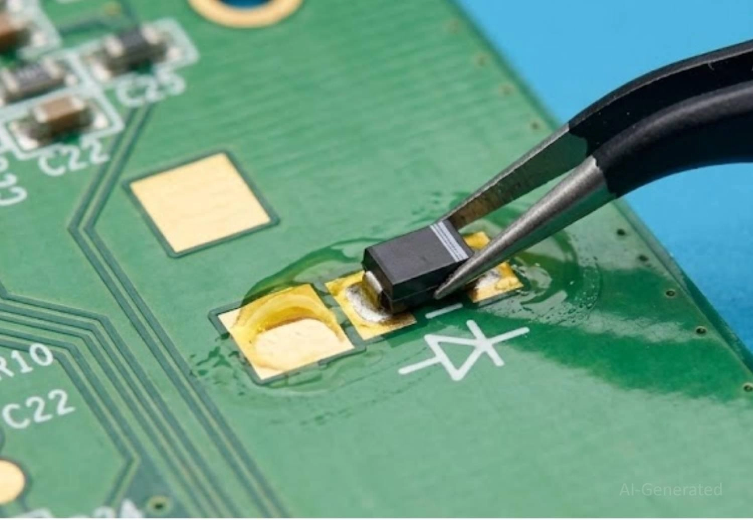
Figure: Proper installation of an SMD diode on a PCB using tweezers, aligning the cathode band with the silkscreen.
If you want to eliminate human error, utilizing professional PCB Assembly services ensures components are placed via automated Pick-and-Place machines and verified with Automated Optical Inspection (AOI), guaranteeing flawless polarity every time.
FAQ About SMD Diode Polarity
Q: How to identify the SMD diode cathode without a multimeter?
Look for a physical marking on the component body. This is usually a white or silver band painted on one end, a laser-etched line, or a molded notch. This mark universally indicates the cathode (-).
Q: What happens if an SMD diode is installed reversed?
It depends on the circuit. It may block current entirely (leaving the circuit dead), or, if it's a flyback or protection diode, it could create a direct short to ground, causing components to overheat, fuses to blow, or traces to melt.
Q: Can a diode be tested while still soldered in the circuit?
Yes, but with caveats. Parallel components (like low-value resistors or inductors) can skew multimeter readings. If you get an abnormal reading or a dead short, you must desolder at least one side of the diode to test it accurately out of circuit.
Q: Can an SMD diode work even if installed in reverse polarity?
In most circuits, a diode installed in reverse polarity will block current flow and prevent the circuit from operating correctly. However, in some protection or clamping applications, reverse bias is intentional. Continuous reverse installation in the wrong circuit path can lead to overheating, voltage stress, or component failure.
Conclusion
Understanding how to identify SMD diode polarity is a non-negotiable fundamental of electronics hardware. Whether you are relying on visual cues like the diode polarity band meaning, translating an SMD diode symbol polarity from a schematic, or performing a diode polarity test with a multimeter, a methodical approach will save you from destroyed PCBs.
Always remember the golden workflow: Visual check → Multimeter verification → Schematic confirmation.
When you are ready to move from breadboards to professional manufacturing, ensuring you have high-quality components is key. You can easily source verified, clearly marked diodes directly from the JLCPCB Parts library. And once your design is finalized, upload your Gerber files and BOM to JLCPCB for an instant PCB quotation to bring your hardware to life flawlessly.
Popular Articles
• SMD Diode Code Lookup: Full List, Marking Guide & Identification [2026 Guide]
• SMD Resistor Package Sizes: Complete Size Chart, Footprints & How to Choose
• SMD Capacitor Codes: Identification, Markings, and Polarity
• SMD Capacitor Sizes: Complete Size Chart and Selection Tips for PCB Design and Assembly
• How to Solder SMD Components Like a Pro [2026 Updated]
Keep Learning
PoP Package (Package on Package) Explained: Architecture, Assembly, and SMT Challenges
In the race for miniaturization, fitting more processing power into smaller footprints is the ultimate challenge for PCB designers. Package on Package (PoP) technology answers this by integrating logic and memory vertically, becoming the standard for modern mobile processors. However, this 3D architecture demands advanced SMT assembly capabilities beyond standard fabrication. JLCPCB specializes in the high-precision manufacturing required to master these complex stacks. This guide covers how PoP packa......
What Is a PQFP Package? Plastic Quad Flat Package Design, Footprint, and Assembly Guide
The Plastic Quad Flat Package (PQFP) is a widely used IC package in industrial, automotive, and embedded designs. This article provides a practical, engineering-focused guide to PQFP package. It explains how PQFP is built, when it makes sense to use it, how it compares with newer package types, and what designers should consider in terms of footprint design, thermal performance, signal integrity, manufacturing, and reliability. What Is a PQFP Package (Plastic Quad Flat Package)? A Plastic Quad Flat Pa......
Small Outline Integrated Circuit (SOIC): Package, Specs & Uses
As designs transition from legacy through-hole components to high-density Surface Mount Technology (SMT), the Small Outline Integrated Circuit (SOIC) remains the industry standard for operational amplifiers, flash memory, sensors, and microcontrollers. It stands as a testament to balanced engineering, offering a perfect compromise between the miniaturisation demanded by modern consumer electronics and the ruggedness required for industrial applications. This article serves as a definitive engineering ......
A Complete Guide to Surface Mount Device (SMD)
Imagine holding a smartphone in your hand. Inside that sleek device lies a complex network of thousands of miniature components — resistors smaller than a grain of rice, capacitors thinner than a fingernail, and integrated circuits containing millions of transistors. Without Surface Mount Technology (SMT) and its compact Surface Mount Devices (SMDs), none of this would exist. Just a few decades ago, electronics were bulky. Radios filled desks, computers filled rooms, and assembling a circuit meant dri......
Circuit Breaker Types Explained: MCB, MCCB, RCCB, RCBO, ACB, VCB & SF6 Circuit Breakers
A circuit breaker automatically disconnects power when it detects faults such as overloads or short circuits, protecting equipment and reducing fire risk. Different circuit breaker types are designed for different voltage levels, current ratings, and applications, from household distribution boards to high-voltage substations. This guide explains the most common types - including MCBs, MCCBs, RCCBs, RCBOs, ACBs, VCBs, and SF6 breakers and helps you choose the right one for your application. Figure: Ci......
Quad Flat Package (QFP): The Engineer's Guide to Design, Assembly and Thermal Management
What is QFP Package? The Quad Flat Package (QFP) is one of the most popular surface mount technology (SMT) package formats throughout the history of electronic manufacturing. After it became standard in the 1980s, the QFP has been the industry standard for integrated circuits (ICs) with moderate to high pin counts that typically range from 32 to 304 pins, so it was a good alternative for simple SOIC packages and complex Ball Grid Arrays (BGAs) at the same time. Defined by its "gull-wing" leads extendi......