
SMD Diode Code Lookup: Full List, Marking Guide & Identification [2026 Guide]
13 min
- Instant SMD Diode Code Lookup Table
- The Ultimate SMD Diode Code List
- How to Identify an Unknown SMD Diode
- How to Identify SMD Diode Polarity
- Understanding SMD Diode Markings
- SMD Diode Package Types and Current Ratings
- How to Test an SMD Diode on a PCB
- Common Diode Mistakes & Wrong Replacement Risks
- SMD Diode Failure Symptoms & Real Repair Scenarios
- How to Replace an SMD Diode Safely
- Why SMD Diode Codes Are Not Standardized
- FAQs
- Conclusion
In modern electronics, surface-mount diodes are used everywhere - from power input protection circuits to high-speed signal routing. Because these components are extremely small, manufacturers cannot print full part numbers on their bodies. Instead, they use short marking codes such as A2, M7, SS14, or SL, which often confuse beginners during PCB repair, reverse engineering, or component replacement.
This guide explains how to decode SMD diode codes, identify polarity, test components using a multimeter, and choose safe replacements, making it easier for engineers, technicians, and hobbyists to troubleshoot modern PCBs with confidence.
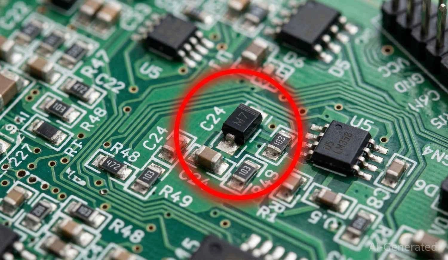
Figure: Macro view of an SMD diode marked M7 on a printed circuit board.
Note
If you see a tiny diode on a PCB with a code like A2, M7, or SS14, this guide will help you instantly identify it, check its polarity, and choose the correct replacement.
Instant SMD Diode Code Lookup Table
The codes below are listed in order of their most common occurrence in power input and signal circuits.
SMD Code | Diode Type / Part Number | Function | Common Package |
|---|---|---|---|
A2 | 1N4148W | High-Speed Switching | SOD-123 |
M7 | 1N4007 | Standard Rectifier | SMA |
SS14 | SS14 | Schottky Barrier | SMA |
A7 | BAV99 | Dual Switching | SOT-23 |
B2 | B120 | Schottky Rectifier | SMA |
SL | SS34 | Low Vf Schottky | SMC |
T4 | 1N4148WS | High-Speed Switching | SOD-323 |
Note: If your diode marking is not in the quick list above, don’t worry. The next sections explain how to systematically identify any unknown SMD diode.
The Ultimate SMD Diode Code List
If you came here searching for a specific SMD diode marking, such as A2, SS14, B2, SL, or T4, use the comprehensive SMD diode code list below to find its electrical rating and package compatibility quickly.
SMD Zener Diode Code List
These Zener diodes are commonly found in voltage regulation circuits for microcontroller power rails.
SMD Code | Zener Voltage (Vz) | Standard Part Number | Common Package |
|---|---|---|---|
W1 | 3.3V | BZT52C3V3 | SOD-123 |
W2 | 3.6V | BZT52C3V6 | SOD-123 |
W3 | 3.9V | BZT52C3V9 | SOD-123 |
W4 | 4.3V | BZT52C4V3 | SOD-123 |
W5 | 4.7V | BZT52C4V7 | SOD-123 |
W8 | 5.1V | BZT52C5V1 | SOD-123 |
W9 | 5.6V | BZT52C5V6 | SOD-123 |
WA | 6.2V | BZT52C6V2 | SOD-123 |
WB | 6.8V | BZT52C6V8 | SOD-123 |
WC | 7.5V | BZT52C7V5 | SOD-123 |
Z1 | 10V | BZT52C10 | SOD-123 |
Z2 | 11V | BZT52C11 | SOD-123 |
Z3 | 12V | BZT52C12 | SOD-123 |
Z4 | 13V | BZT52C13 | SOD-123 |
Z5 | 15V | BZT52C15 | SOD-123 |
Table: Comprehensive lookup chart for Zener diode SMD codes, listing codes alongside their corresponding Zener voltages from 3.3V to 15V, part numbers, and SOD-123 package types.
Schottky Diode Code List
Schottky diodes like these are widely used in buck/boost converters and solar power management boards.
SMD Code | Current / Voltage Rating | Standard Part Number | Common Package |
|---|---|---|---|
SS14 | 1A / 40V | SS14 | SMA |
SS34 | 3A / 40V | SS34 | SMC |
B120 | 1A / 20V | B120 | SMA |
B140 | 1A / 40V | B140 | SMA |
KL3 | 200mA / 30V | BAT54 | SOT-23 |
KL4 | 200mA / 30V | BAT54S (Dual) | SOT-23 |
JV3 | 200mA / 30V | BAT54C (Dual) | SOT-23 |
L4 | 200mA / 30V | BAT54A (Dual) | SOT-23 |
SL | 1A / 40V | B5819W | SOD-123 |
S4 | 350mA / 40V | SD103AW | SOD-123 |
Table: Reference chart for Schottky diode SMD codes, their current and voltage ratings, part numbers, and package types.
Switching Diode Code
You will frequently find these fast-switching diodes in logic-level shifting and debouncing circuits.
SMD Code | Configuration | Standard Part Number | Common Package |
|---|---|---|---|
A2 | Single | 1N4148W | SOD-123 |
T4 | Single | 1N4148WS | SOD-323 |
A7 | Dual Series | BAV99 | SOT-23 |
A4 | Dual Common Cathode | BAV70 | SOT-23 |
A1 | Dual Common Anode | BAW56 | SOT-23 |
5D | Single | MMBD4148 | SOT-23 |
JV | Dual Common Anode | BAV70S | SOT-363 |
KJM | Single | BAV19W | SOD-123 |
T6 | Single | 1N4448WS | SOD-323 |
A6 | Single | BAS16 | SOT-23 |
Table: Identification table for Switching diode SMD codes, their single or dual configurations, part numbers, and corresponding packages.
TVS Diode Codes
TVS diodes are critical for shunting high-voltage electrostatic discharge safely to ground before it reaches the CPU.
SMD Code | Breakdown Voltage | Stand-off Voltage | Package |
|---|---|---|---|
LE | 6.4V | 5.0V | SMA |
CA | 13.3V | 12.0V | SMA |
BM | 26.7V | 24.0V | SMA |
HE | 6.4V | 5.0V | SMB |
PX | 16.7V | 15.0V | SMC |
Table: Lookup guide for TVS diode SMD codes, showing codes, their breakdown, and stand-off voltages, and standard DO-214 packages.
How to Identify an Unknown SMD Diode
Follow this field-tested workflow to decode any diode on your board:
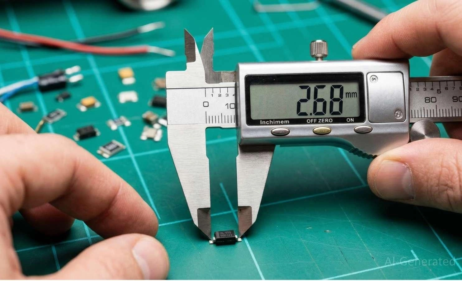
Figure: Measuring an SMD diode package size using digital calipers for component identification.
SMD Diode Identification: Step-by-Step
- Read marking using a jeweler's loupe or a macro phone camera with angled lighting.
- Measure package size (length and width) with digital calipers (e.g., SOD-323, SMA).
- Check the circuit location to deduce its function.
- Cross-reference lookup table to match the code and package to a standard part number.
- Verify using a multimeter to confirm the forward voltage drop.
How to Identify Diode Function from Circuit Role
- Across a relay coil: Flyback diode (snubber).
- In series with power input: Reverse polarity protection.
- Near a crystal oscillator/MCU: High-speed signal switching.
- Near USB/HDMI ports: ESD TVS (Transient Voltage Suppression).
What if the Code is Burnt, Scratched, or Missing? Use PCB trace routing to identify the circuit function, check the surrounding components, and measure the reverse voltage of the circuit.
Engineer Tip
Always check if the diode is part of a voltage regulator feedback path before replacing it. Installing the wrong replacement here may cause an unstable output voltage and damage the board immediately.
For precise replacements and exact footprint matching, utilize the JLCPCB Parts Product Page.
How to Identify SMD Diode Polarity
Identifying the polarity of an SMD diode is just as critical as ensuring correct capacitor polarity. Installing it backward will result in circuit failure.
- The Cathode Band: The cathode (negative terminal) is typically marked with a laser-etched or printed line across one end of the black package. This corresponds to the line on the diode schematic symbol.
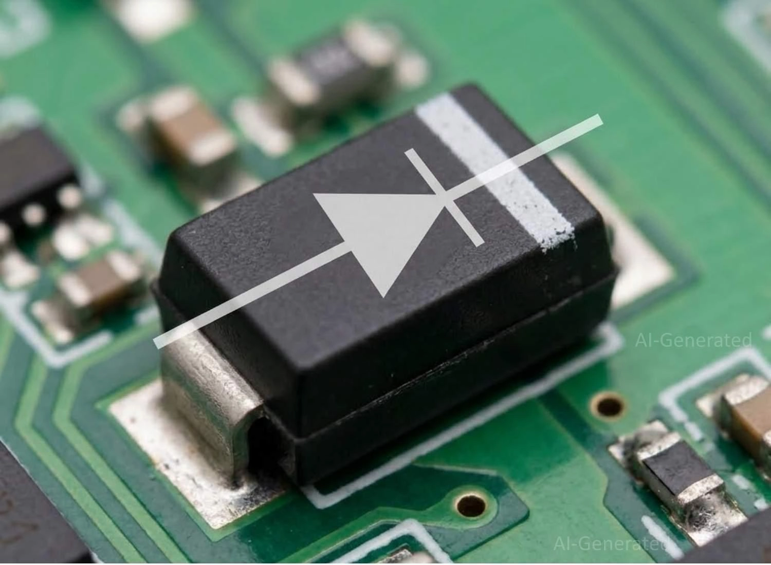
Figure: SMD diode polarity test showing the white cathode band on an SMA package aligned with a diode schematic symbol.
- Multi-Pin Packages (SOT-23): SOT-23 diodes typically have three pins and do not feature dot markings or cathode bands. Because they often contain dual diodes arranged in common cathode, common anode, or series configurations, you must rely on the manufacturer's datasheet to map the pinout correctly.
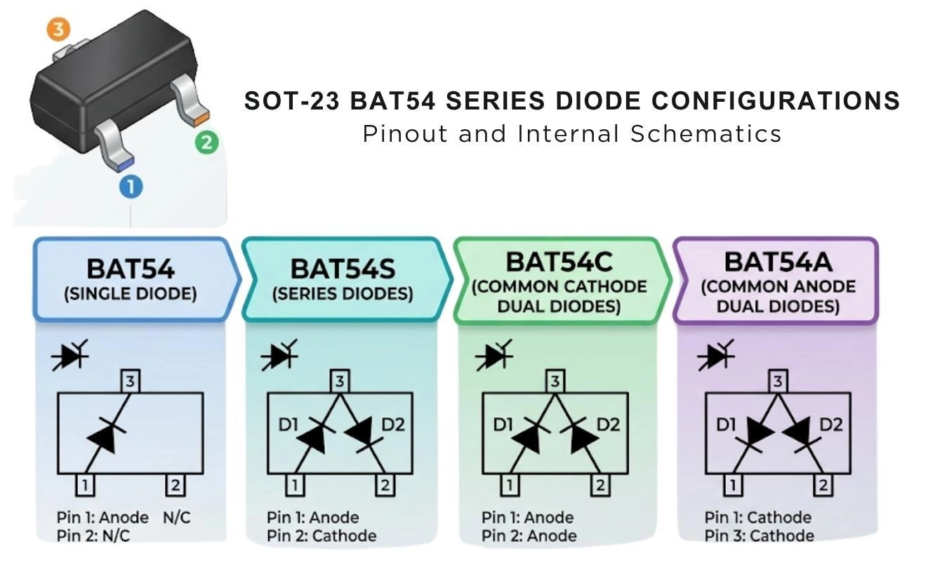
Figure: An SOT-23 package showing the standard asymmetric pin numbering (Pins 1 and 2 on the bottom, Pin 3 on the top) alongside internal schematic variations like the BAT54 series.
Understanding SMD Diode Markings
Manufacturers print short marking codes because modern SMD packages are extremely small. However, typing "A2 datasheet" into a search engine rarely works because these codes are internal abbreviations. You must first translate the printed code into the actual part number using a lookup table.
Warning: Diode Code Confusion
The same SMD diode code can represent entirely different components depending on the manufacturer and the package type. Always confirm using a datasheet and forward voltage testing.
SMD Diode vs. Resistor Code Differentiation
A huge beginner frustration is confusing tiny black rectangular components.
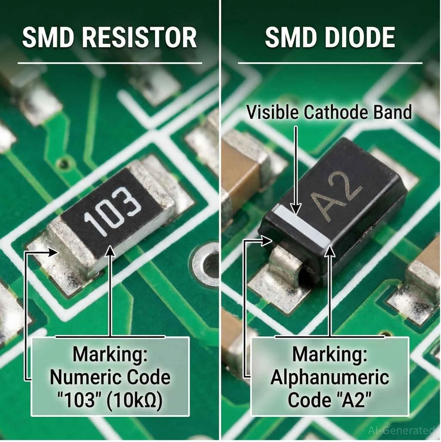
Figure: Visual comparison between a numeric SMD resistor code and an alphanumeric SMD diode code with a cathode polarity band.
Resistors: Typically use purely numeric codes (e.g., "103" for 10kΩ) and have no polarity markings. (See our comprehensive SMD resistor code guide.)
Diodes: Use alphanumeric combinations (e.g., "A2", "SS14") and always feature a cathode band or physical polarity marker.
Also Read: SMD Capacitor Codes: Step-by-Step Guide
SMD Diode Package Types and Current Ratings
To help you connect a component's package to its function, here is a comparison logic chart based on real physical numbers and typical current handling.
Package Name | Dimensions (L x W approx) | Typical Current Rating | Typical Application |
|---|---|---|---|
SOD-523 | 1.2mm x 0.8mm | < 200mA | Ultra-small mobile devices & wearables |
SOD-323 | 1.7mm x 1.25mm | ~ 200mA - 500mA | Signal processing / small power |
SOD-123 | 2.7mm x 1.6mm | ~ 1A | Moderate power/signal isolation |
SMA (DO-214AC) | 4.3mm x 2.6mm | 1A - 2A | Rectifiers / main power paths |
SMB (DO-214AA) | 4.3mm x 3.6mm | 2A - 3A | Heavy rectifiers / TVS protection |
Table: Comparison chart of SMD diode package types, listing their approximate dimensions, typical current ratings, and common applications.
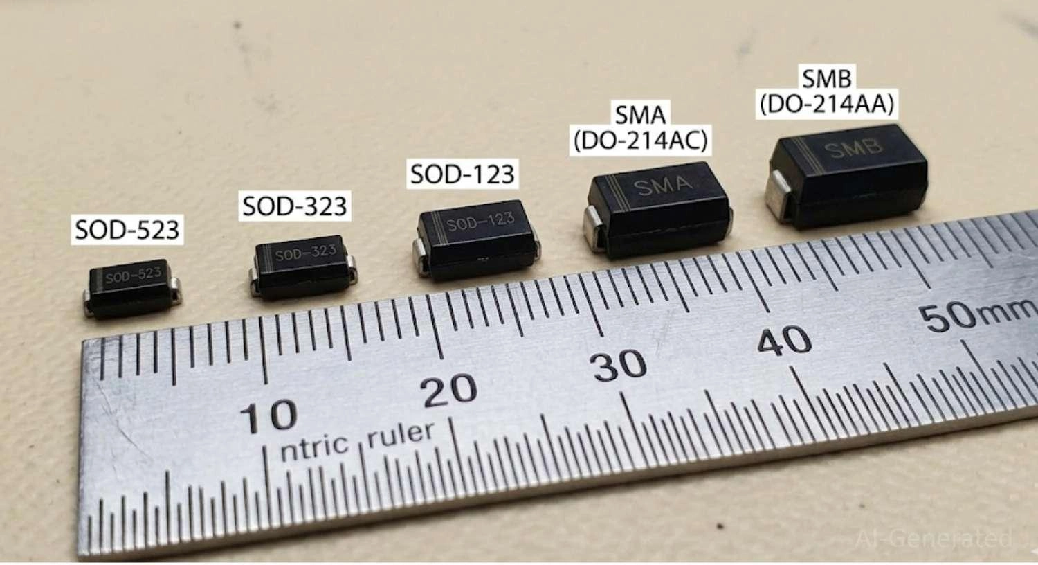
Figure: Size comparison of SMD diode packages SOD-523, SOD-323, SOD-123, SMA, and SMB next to a metric ruler.
How to Test an SMD Diode on a PCB
Before replacing a suspect part, test both its polarity and electrical condition with a digital multimeter.
The Multimeter Method: Set your DMM to "Diode Mode". Place the red probe on the anode (unmarked side) and the black probe on the cathode (banded side).
Parallel components can distort in-circuit readings. If the measurement looks suspicious, lift one pad of the diode and test it again out of circuit.
Forward Voltage Interpretation: If the code is illegible, the forward voltage (Vf) drop is a powerful diagnostic guide:
- Vf < 0.4V → Schottky diode
- Vf ≈ 0.6V – 0.75V → silicon switching diode
- Vf ≈ 0.7V – 1.0V → power rectifier
- OL reading → open diode (blown internally)
- 0.0V beep → shorted diode
The Reverse Bias Tip (Advanced): Always swap the probes (black to anode, red to cathode). A healthy diode should show "OL" (Over Limit). If you see a voltage reading or get a beep, the diode is leaking or shorted. In high-voltage circuits, a diode may show a correct forward voltage but leak excessively under reverse-bias conditions, causing overheating and unstable operation.
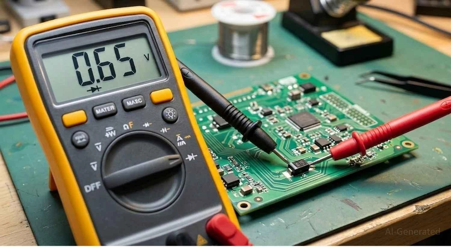
Figure: Testing SMD diode forward voltage on a PCB using a digital multimeter set to diode mode.
Common Diode Mistakes & Wrong Replacement Risks
- Installing a diode in reverse polarity: This immediately blocks intended power flow or causes a direct short circuit.
- Choosing a lower reverse voltage rating: Leads to immediate punch-through failure the moment the circuit is powered.
- Confusing Schottky with silicon diode: Silicon diodes have a higher forward voltage drop. Swapping a Schottky for a silicon diode in a power circuit causes excess heat and voltage loss.
- Selecting the wrong package footprint: A smaller package will overheat rapidly under the same current load, even if the electrical specs match.
- Reading the code upside down: Misinterpreting a "6" for a "9" or an "M" for a "W" is a frequent identification error. Always orient the text relative to the cathode band.
SMD Diode Failure Symptoms & Real Repair Scenarios
Root Causes of Diode Failure: Surge damage (lightning or static), reverse polarity events, severe overheating, or manufacturing defects. Repeated thermal cycling can also crack internal wire bonds in SMD diodes, leading to intermittent faults that are difficult to diagnose.
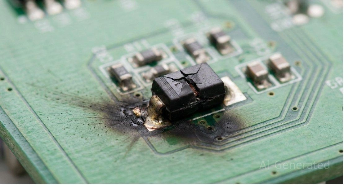
Figure: Burnt and cracked SMD diode on a printed circuit board indicating catastrophic failure.
Real PCB Repair Scenario: A burnt diode marked ‘M7’ was found near the DC input of a router board. After testing it with a multimeter, it produced a continuous beep, indicating a dead short. Because it was shorted, the router's power supply was triggering over-current protection. By desoldering the dead component and replacing it with a fresh SMA-package 1N4007, the board's power circuitry was restored perfectly.
When attempting repairs, thermal management is key. Brush up on how to achieve perfect PCB soldering and reflow soldering techniques to ensure you don't damage surrounding pads when removing blown components.
How to Replace an SMD Diode Safely
Replacing these tiny components requires a steady hand and proper methodology to avoid damaging the PCB traces.
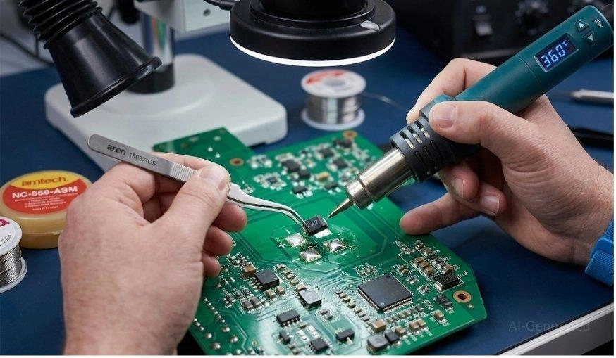
Figure: Technician safely removing an SMD diode from a PCB using a hot air rework station and precision tweezers.
Safe SMD Diode Replacement Steps
- Confirm polarity orientation before component removal.
- Use flux + controlled heat (hot air rework station or fine-tipped soldering iron).
- Clean pads thoroughly with solder wick and isopropyl alcohol before soldering.
- Test forward voltage and continuity after installation to ensure a solid electrical connection.
Why SMD Diode Codes Are Not Standardized
If you are wondering why identifying these components is so chaotic:
- No global registry: Semiconductor manufacturers like Vishay, ON Semiconductor, and Nexperia all have their own proprietary lookup tables.
- Space limits: The legacy JEDEC numbering system (like 1N4148) requires 6 characters. You physically cannot laser-etch 6 characters onto a 1.2mm SOD-523 package.
- Subcontractor variations: Different assembly and testing facilities may use slightly different laser markings or batch codes for the same basic part.
FAQs
Q: How do I read an SMD diode code without a microscope?
Use your smartphone's camera. Switch to macro mode, zoom in, and use a flashlight at a 45-degree angle to cast shadows on the laser etching.
Q: What does "SS" mean in diode marking?
It typically denotes a Surface Mount Schottky diode (e.g., SS14, SS34).
Q: Why do some SMD diodes have only two letters?
Strict space limits. Two letters provide enough unique combinations for a specific manufacturer's lookup table for that particular package size.
Q: Are SMD diode codes the same worldwide?
No. They are highly manufacturer-dependent.
Q: How do I identify the SOD-323 diode size?
Measure the main body (excluding the metal leads). A SOD-323 measures approximately 1.7mm x 1.25mm.
Q: Can an SMD diode code be fake or relabeled?
Yes, especially in gray-market sourcing. Counterfeiters often laser-mark cheap switching diodes with Schottky codes.
Q: How do I identify a diode without a schematic?
Use contextual trace routing (where does the trace go?), package measuring, and forward-voltage testing.
Q: What happens if a diode is installed backward?
Depending on the circuit, it can result in immediate circuit failure, blown fuses, or catastrophic damage to downstream ICs.
Conclusion
By mastering the fundamental workflow - Read the Code -> Measure the Package -> Test with a Multimeter -> Verify the Datasheet -> Replace - you can confidently tackle any PCB repair or reverse engineering project.
Relying on physical measurements and forward-voltage testing will always guide you to the correct component. Keep this guide bookmarked as your go-to reference whenever you encounter an unknown SMD diode.
Popular Articles
• SMD Capacitor Sizes: Complete Size Chart and Selection Tips for PCB Design and Assembly
• SMD Diode Code Lookup: Full List, Marking Guide & Identification [2026 Guide]
• SMD Resistor Package Sizes: Complete Size Chart, Footprints & How to Choose
• SMD Capacitor Codes: Identification, Markings, and Polarity
• How to Solder SMD Components Like a Pro [2026 Updated]
Keep Learning
Thin Film vs. Thick Film Resistors: Key Differences, Advantages & Applications
Key Takeaways Default to thick film resistors for most designs. They are cost-effective, robust, and ideal for pull-ups, LED current-limiting, digital circuits, and surge-prone applications. Choose thin-film resistors whenever a resistor defines an analog quantity, such as a voltage divider, reference network, gain-setting circuit, or current-sensing signal chain. Their tight tolerance and low TCR help maintain measurement accuracy over temperature and time. Most PCB designs use thick film or thin fil......
What Is the ESP32? A Complete Guide to Features, Architecture, Modules, Programming, and Applications
From Wi-Fi-enabled temperature sensors and wearable health monitors to industrial gateways and AI-powered cameras, the ESP32 microcontroller has become one of the world's most widely adopted wireless embedded platforms. Combining a powerful processor with integrated Wi-Fi and Bluetooth, it lets engineers build connected devices without separate networking hardware. This guide covers ESP32 specifications, architecture, the full family of variants, development boards, programming tools, and real-world E......
How to Choose the Right STM32 Microcontroller: Compare Series, Cortex-M Cores, and Key Features
STMicroelectronics ships thousands of STM32 MCU part numbers across more than a dozen series, and that variety is exactly what makes STM32 microcontroller selection difficult. Pick the wrong family, and you pay for it later: oversized BOM cost, wasted power budget, or a board respin when a peripheral turns out to be missing. This STM32 microcontroller selection guide breaks the decision into a five-step framework built on practical engineering criteria, not datasheet marketing copy, so you can match a......
SMD Transistor Code Lookup: Identify Markings, Pinout & Multimeter Test Guide
Repairing a circuit board often brings a familiar frustration: staring at a tiny, three-legged black component with an obscure two- or three-letter code. Whether troubleshooting a bare prototype or a mass-produced PCBA, knowing how to quickly decode these surface-mount device (SMD) markings is an essential skill for any electronics engineer or repair technician. In this comprehensive guide, you will learn: 1. How to decode SMD transistor marking codes 2. How to identify BJT vs MOSFET types 3. How to f......
SMD Capacitor Sizes: Complete Size Chart and Selection Tips for PCB Design and Assembly
In the world of modern electronics, surface mount devices (SMDs) have revolutionized board design, allowing for smaller, faster, and more efficient printed circuit boards. When designing a PCB, selecting the correct SMD capacitor sizes is one of the most critical decisions an engineer must make to ensure both electrical reliability and manufacturability. In this article, you will find practical, authoritative guidance on: Comprehensive SMD capacitor size charts for quick reference. How to read imperia......
SMD Diode Code Lookup: Full List, Marking Guide & Identification [2026 Guide]
In modern electronics, surface-mount diodes are used everywhere - from power input protection circuits to high-speed signal routing. Because these components are extremely small, manufacturers cannot print full part numbers on their bodies. Instead, they use short marking codes such as A2, M7, SS14, or SL, which often confuse beginners during PCB repair, reverse engineering, or component replacement. This guide explains how to decode SMD diode codes, identify polarity, test components using a multimet......