
SMD Resistor Package Sizes: Complete Size Chart, Footprints & How to Choose
17 min
- Complete SMD Resistor Size Chart for Fast Reference (Imperial and Metric)
- What the SMD Resistor Size Codes Mean (Imperial vs Metric)
- Recommended PCB Footprints & Land Pattern Guidelines
- SMD Resistor Package Size: Impacts on Electrical, Thermal, and Mechanical Performance of the PCB
- SMD Resistor Package Size: Manufacturing and Assembly Considerations
- Common Mistakes Engineers Make When Selecting SMD Resistor and How to Fix
- How to Choose the Right SMD Resistor Package Size for Your Project
- How JLCPCB Supports the SMD Resistor Package Selection
- Conclusion
- FAQs about SMD Resistor Package Sizes
Surface Mount Device (SMD) resistors are fundamental to modern electronics, and selecting the correct package size is a crucial engineering decision that impacts a PCB’s electrical performance, thermal reliability, and manufacturing cost.
In this article, you will find practical, authoritative guidance on:
- The complete SMD resistor size chart (01005 to 2512) with exact dimensions and power ratings.
- Recommended PCB footprints and guidelines for reflow reliability.
- Critical trade-offs concerning power dissipation, assembly ease, cost, and mechanical stability.
- Real-world application examples for consumer, IoT, and power circuits.
Complete SMD Resistor Size Chart for Fast Reference (Imperial and Metric)
| Package Code(Imperial) | Package Code(Metric) | Length (L) ± Tolerance | Width (W) ± Tolerance | Height (H)Typical | Power Rating (W) | Applications |
|---|---|---|---|---|---|---|
| 01005 | 0402 | 0.016*/0.40 mm | 0.008*/0.20 mm | 0.005*/0.13 mm | 31/1000W (0.031W) | Ultra-compact RF modules, mobile & wearable electronics |
| 0201 | 0603 | 0.024*/0.60 mm | 0.012*/0.30 mm | 0.010*/0.25 mm | 1/20W (0.05W) | Smartphones, IoT sensors, compact logic circuits |
| 0402 | 1005 | 0.04*/ 1.00 mm | 0.02″/0.50 mm | 0.014″/ 0.35 mm | 31/500W (0.062W) | High-density PCBs, medical and wearable devices |
| 0603 | 1608 | 0.06″/ 1.55 mm | 0.03″/ 0.85 mm | 0.018″/ 0.45 mm | 1/10W (0.10W) | Consumer electronics, signal conditioning, and filtering |
| 0805 | 2012 | 0.08″/2.00 mm | 0.05″/ 1.25 mm | 0.018″/ 0.45 mm | 1/8W (0.125W) | Industrial PCBs, LED drivers, embedded systems |
| 1206 | 3216 | 0.12″/ 3.10 mm | 0.06″/ 1.55 mm | 0.022″/ 0.55 mm | 1/4W (0.25W) | Automotive electronics, power monitoring circuits |
| 1210 | 3225 | 0.12″/ 3.10 mm | 0.10″/ 2.50 mm | 0.022″/ 0.55 mm | 33/100W (0.33W) | Power supplies, battery chargers, DC/DC converters |
| 1812 | 4532 | 0.18″/ 4.50 mm | 0.12″/ 3.20 mm | 0.024″/ 0.60 mm | 3/4W(0.75W) | High-power density circuits,Motor control, power amplifiers |
| 2010 | 5025 | 0.20″/ 5.00 mm | 0.10″/ 2.50 mm | 0.024″/0.60 mm | 1/2W (0.5W) | Regulation circuits, industrial modules, precision loads |
| 2512 | 6332 | 0.25″/ 6.35 mm | 0.12″/ 3.20 mm | 0.024″/ 0.60 mm | 1/1W (1W) | Power systems, high current paths, motor drivers |
Note
Why This SMD Resistor Size Chart Matters for Engineers
1. It helps to select the right packages for performance requirements. Smaller packages (01005-0402) are ideal for ultra-compact designs but have lower power ratings and higher assembly complexity.
2. It prevents footprint mismatch and assembly defects.
3. It controls cost and manufacturing.
What the SMD Resistor Size Codes Mean (Imperial vs Metric)
Learning the SMD resistor package code is important for right component selection, footprint design and BOM verification.
Engineers frequently face confusion when switching between imperial codes (0603, 0805, etc.) and metric codes (1608, 2012, etc.). This section explains both systems clearly and highlights important conversion rules, tolerances, and pitfalls.
What is Imperial Code?
The imperial coding system is a commonly used naming convention for SMD resistors in the United States and global component suppliers. In this system:
The 4-digit number represents length and width in hundredths of an inch:
For example:
- 0603 - 0.060” x 0.030”
- 0402 - 0.040” x 0.020”
- 0805 - 0.080” x 0.050”
Each code directly tells you the physical size of the SMD resistor.
Why Is the Imperial Code Widely Used?
- It is the default size labeling in most component datasheets.
- Major manufacturers like Yageo, Vishay, Panasonic, Samsung, and Rohm use imperial as their primary naming standard.
- Pick-and-place libraries and most PCB software libraries (KiCad, Altium, Eagle) are designed around imperial codes.
But the imperial system has certain drawbacks as well:
- It does not express the “height” of the resistors, which varies by manufacturer.
- Two different manufacturers may produce 0603 resistors with slightly different tolerances.
- Converting to millimeters is not intuitive for international teams.
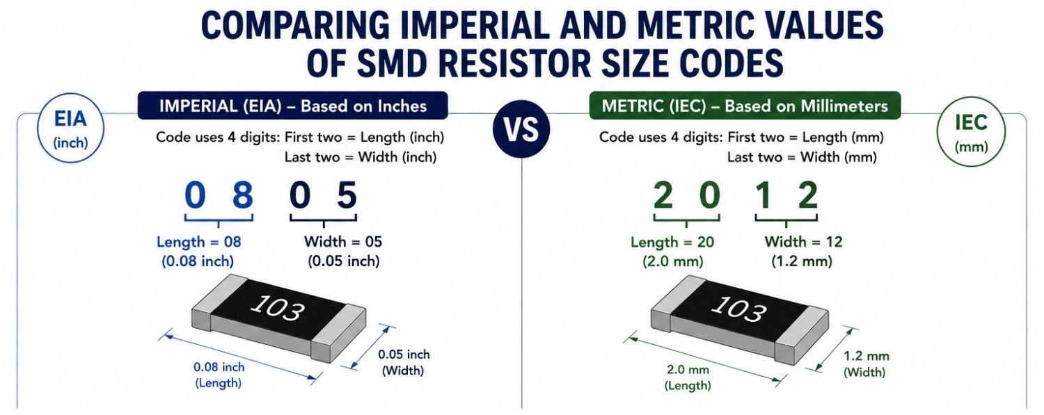
Figure: Comparison of Imperial (0805) and Metric Code (2012) of the same-sized resistor package
What is Metric Code and Common Conversions
The metric (IEC) SMD resistor code is expressed in hundredths of millimeters, giving a more precise unit-based physical representation.
The 4-digit metric number represents length and width in tenths of millimeters (mm).
Examples:
- 1608- 1.6 mm x 0.8 mm (Imperial 0603)
- 1005- 1.0 mm x 0.5 mm (Imperial 0402)
- 2012- 2.0 mm x 1.2 mm (Imperial 0805)
Advantages of the metric system:
- More precise unit-based sizing (mm instead of inches)
- Increasingly used in Europe and Japan.
- IPC standards and some CAD tools reference metric land pattern dimensions.
But there's a catch: Metric codes look similar but are not interchangeable with imperial.
Example:
- 0402 imperial is 1005 metric.
- But 0402 metric would incorrectly mean 0.4 mm x 0.2 mm—actually 01002 imperial (not a standard size)
Therefore, mixing metric and imperial code is a common source of engineering mistakes.
Manufacturer Tolerances
Even though size codes represent standard dimensions, actual tolerances vary across manufacturers, affecting:
- Pad size
- Solder mask opening
- Reflow profile behaviour
- Thermal dissipation capability
Common Designer Mistakes in PCB Footprint and Package Selection
- Assuming 0603=0603 everywhere. Some suppliers produce thin-film vs thick-film variants with different heights.
- Creating footprints based purely on the package. Manufacturers often specify unique pad tolerances.
- Mixing metric and imperial codes on BOMs leads to incorrect part placement, procurement errors, and assembly mismatches.
Which Standard Applies — EIA vs IEC?
EIA (Electronics Industries Alliance) corresponds to the imperial naming system.
IEC (International Electrotechnical Commission) corresponds to the metric system.
Both systems describe the same physical parts but use different code formats. Modern CAD systems are shifting towards IEC metric footprints, while component distributors still list parts in EIA imperial.
Recommended PCB Footprints & Land Pattern Guidelines
A perfectly selected SMD resistor can still cause failure if its PCB footprint (land pattern) is not designed correctly. Proper pad sizing, spacing, solder mask definition, and stencil aperture design are essential for preventing defects such as tombstoning, skewing, insufficient solder joints, and thermal imbalance.
Why Do Footprints Matter in PCB Design?
SMD resistors rely entirely on solder joints for mechanical strength, electrical contact, and thermal conduction.
An incorrect footprint causes:
- Poor wetting and weak joints.
- Excess solder is causing short circuits.
- Tombstoning during reflow
- Skewing or rotation due to unequal solder surface tension.
- Long-term reliability loss from cracked joints
Therefore, PCB footprints must follow IPC recommendations (IPC-7351) and incorporate manufacturer-specific tolerances.
Recommended Land Patterns (0402, 0603, 0805, 1206)
Below are IPC-7351 nominal footprint recommendations commonly used for SMD resistor land patterns. Actual dimensions may vary depending on manufacturer specifications, assembly process capability, solder paste volume, and density level requirements.
0402 (1005 Metric) footprint
- Pad length (A): 0.50-0.60 mm
- Pad width (B): 0.30-0.40 mm
- Pad-to-pad gap (C): 0.30-0.40 mm
- Overall land length (D): 1.30-1.60 mm
Note: 0402 components are extremely small and sensitive to tombstoning during reflow. Symmetric pad geometry and balanced copper routing are critical.
0603 (1608 Metric) footprint
- Pad length (A): 0.80-0.95 mm
- Pad width (B): 0.50-0.60 mm
- Pad-to-pad gap (C): 0.50-0.70 mm
- Overall land length (D): 2.10-2.60 mm
Note: 0603 packages provide a strong balance between routing density, manufacturability, and assembly reliability, making them common in consumer electronics.
0805 (2012 Metric) footprint
- Pad length (A): 1.05-1.25 mm
- Pad width (B): 0.80-1.00 mm
- Pad-to-pad gap (C): 0.70-1.00 mm
- Overall land length (D): 2.80-3.50 mm
Note: 0805 footprints are easier to hand solder and offer improved thermal tolerance compared to smaller package sizes.
1206 (3216 Metric) footprint
- Pad length (A): 1.30-1.60 mm
- Pad width (B): 1.10-1.40 mm
- Pad-to-pad gap (C): 1.00-1.40 mm
- Overall land length (D): 3.60-4.60 mm
Note: 1206 packages are commonly used in higher-power applications requiring greater heat dissipation and improved current handling.
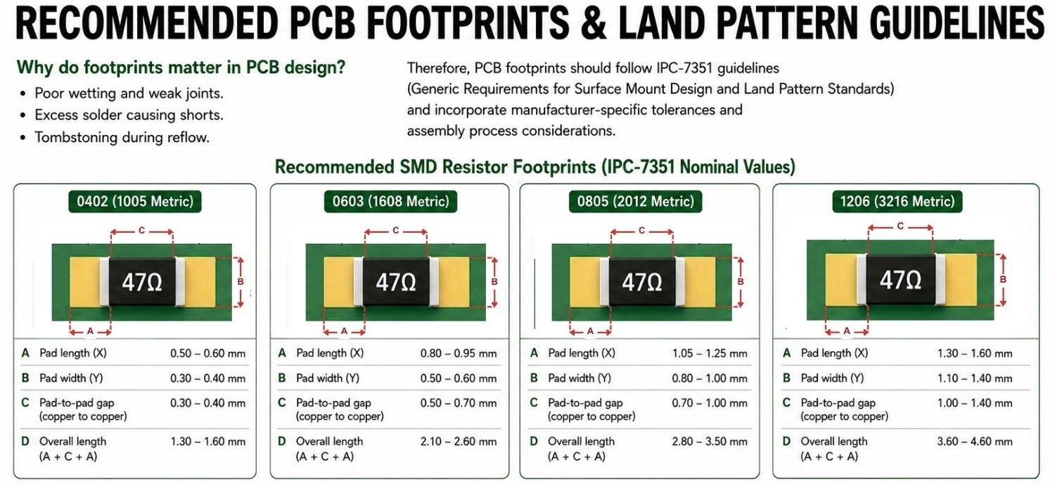
Figure: Recommended PCB footprints and land pattern for 0402, 0603, 0805, and 1206 SMD resistors.
SMD Resistor Package Size: Impacts on Electrical, Thermal, and Mechanical Performance of the PCB
Power Rating and Thermal Capacity
Power dissipation scales strongly with physical size. Larger packages have more ceramic volume, thicker terminations, and a larger surface area to allow heat to dissipate efficiently into the PCB.
If a resistor is dissipating significant power (P=I²R), smaller packages such as 0201 and 0402 will exhibit a rapid temperature rise due to limited thermal mass, leading to resistance drift, accelerated aging, and even cracking.
Power Ratings By Size of SMD Resistor
- 01005: 0.031 W
- 0201: 0.05 W
- 0402: 0.063 W
- 0603: 0.10 W
- 0805: 0.125 W
- 1206: 0.25 W
- 1210: 0.33 W
- 2010/1812: 0.75 W
- 2512: 1.0 W
Most parts require derating above 70°C, with smaller sizes derating more aggressively. This is why automotive and industrial designs prefer 0805 and above for power-intensive nodes.
Tolerance, Stability, and Noise Performance
Component size directly impacts precision. Ultra-small resistors contain minimal resistive film, making consistent deposition difficult.
Tolerance:
- 0201/0402: typically ±5%
- 0603/0805: ±1–5%
- 1206+: precision grades down to ±0.1%
TCR Stability:
- 201/0402: 100–300 ppm/°C
- 0603–1206: 25–100 ppm/°C
- Thin-film precision: as low as 5 ppm/°C
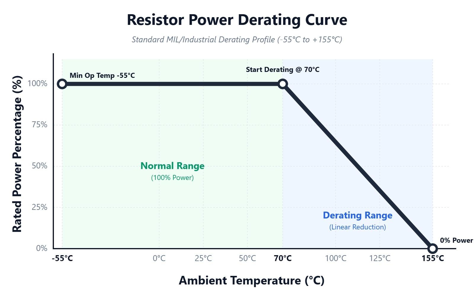
Figure: Resistor power derating curve
Mechanical Strength and Stress Resistance
Mechanical robustness improves with package size. Small resistors have limited solder fillet volume and thinner ceramic bodies, making them vulnerable to flex cracking, vibration, and thermal shock. Sizes 0805, 1203, and 1210 provide superior resistance to board bending and harsh thermal cycling essential for AEC-Q200 automotive compliance.
Pick-and-Place Reliability
Miniature packages like 01005/0201 demand advanced placement equipment and exhibit higher tombstoning and misalignment rates.
Mid-sized packages (0603/0805) provide excellent placement accuracy and reworkability, making them the industry standard for high-volume production.
Larger packages (1206/2512) are easy to handle but require well-balanced pad geometry to prevent shifting during reflow.
SMD Resistor Package Size: Manufacturing and Assembly Considerations
Manufacturing quality in PCB assembly depends not only on selecting the correct surface mount resistor package size but also on how those components behave across solder paste deposition, pick-and-place placement, and reflow soldering.
As resistors get smaller, their assembly tolerances become narrower, making package size a critical variable in yield, defect rate, and long-term field reliability.
Pick-and-Place Machine Capability and Assembly Tolerance
1. Ultra-small Packages (01005 and 0201)
These tiny resistors demand exceptional machine accuracy. Their small mass and footprint mean even slight variations in solder volume or air turbulence can shift components during placement. Only advanced SMT lines support these sizes reliably. This directly increases the assembly cost and restricts manufacturer options.
2. Standard manufacturing workhorses: 0402 and 0603
Most modern SMT machines achieve optimal accuracy with 0402 and 0603 resistors. These types of resistors have excellent pick-and-place recognition and high placement throughput (up to 40,000 CPH). For 95% of consumer electronics, 0603 remains the best for manufacturing, cost, and reliability.
3. Larger packages (0805 and above)
These sizes are easier to handle, inspect, and rework. AOI identification is highly reliable. However, their larger thermal mass creates an interesting challenge: if pad symmetry is not perfect, larger resistors experience higher skewing or tombstoning forces during reflow.
Solder Paste Stencil Aperture Guidelines
Solder paste release consistency is directly tied to package size. Incorrect aperture design leads to skew, solder starvation, or bridging.
Stencil Thickness
| Package Size | Ideal Thickness |
|---|---|
| 01005 / 0201 | 80–100 µm |
| 0402 / 0603 | 100–120 µm |
| 0805+ | 120–150 µm |
Aperture Reduction (5-10%)
Reducing the aperture prevents:
- Excess solder deposition
- Component float
- Solder bridging
- Thermal imbalance
SMD Resistor Package Size Impact on Assembly Yield
| Size | Difficulty | Defect Risk | Cost Impact |
|---|---|---|---|
| 01005/0201 | Very High | Extreme | High |
| 0402 | High | Moderate | Medium |
| 0603 | Low | Low | Best |
| 0805+ | Very Low | Very Low | High Reliability |
Note: The professionals frequently select the 0603 and 0805 due to the thermal stability.
Common Mistakes Engineers Make When Selecting SMD Resistor and How to Fix
Even experienced designers miscalculate the impact of surface mount resistor package size, often leading to field failures, solder defects, and unexpected reliability issues. These mistakes typically result from shortcuts taken during schematic design or a misunderstanding of how size affects electrical, thermal, and mechanical behaviour.
Mistake 1: Choosing a Smaller Package to Save PCB Space
Reducing the SMD resistor size simply to reduce the board area is one of the most common engineering mistakes. Reducing the size of 0603 to 0402 and 0402 to 0201 impacts the thermal performance of the PCB.
To fix this:
- Always check the thermal derating curve.
- Avoid 0402 in power or analog stability-sensitive paths.
Mistake 2: Ignoring Mechanical Strength and Package Height
Engineers often compare only footprint dimensions, ignoring height. Low-profile packages crack more, especially during flexing.
To fix this: Use 0805 or 1206 for mechanically stressed boards (LED strips, long PCBs, automotive).
Mistake 3: Using the Wrong PCB Footprint
Wrong footprints cause more field failures than wrong SMD resistor values.
To fix this: Always follow the IPC-7351 manufacturer's datasheet.
Mistake 4: Confusion between Imperial and Metric Codes
This mistake has caused many assembly errors, such as incorrect footprint matching, incorrect part ordering, and poor assembly.
To fix this: Always list both codes in the BOM and CAD library.
How to Choose the Right SMD Resistor Package Size for Your Project
Choosing the proper SMD resistor package size requires balancing power, space, reliability, manufacturability, and performance. Follow these steps to choose the right SMD resistors:
Step 1: Calculate Actual Power Requirement
- Current-driven circuits: P = I²R
- Voltage-driven circuits: P = V²/R
Choose a package that supports 2x the calculated power.
Step 2: Consider Temperature and Derating
Above 70°C, all resistors must be derated. Smaller packages derate more.
Rule of thumb: If your board can reach 80–100°C, avoid running resistors close to their maximum rating. Go one size larger.
Step 3: Evaluate PCB Space and Density
If a compact form factor is a priority (IoT, wearables), 0402 or 0603 may be required.
Step 4: Determine Electrical Precision Requirements
For analogue and RF precision:
- Choose thin film 0603 or 0805
- Prefer low ppm (25-100 ppm/°C)
- Avoid 0402 for high stability requirements.
Step 5: Mechanical Reliability
If the PCB will face vibration, shock, or bending (automotive, industrial, motor drivers, long boards), prefer larger packages like 0805 or 1206.
For hand-soldered and reworked boards, use 0805 and 0603 surface-mount resistor packages.
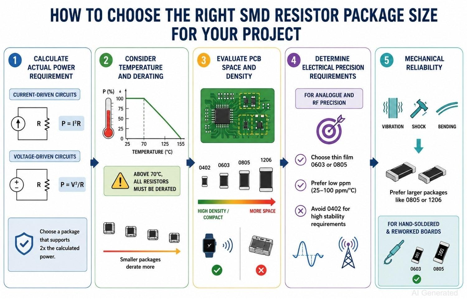
Figure: Steps to select the appropriate SMD resistor package size for an electronic project
How JLCPCB Supports the SMD Resistor Package Selection
Component selection must be aligned with your PCB assembly partner’s capabilities. JLCPCB’s manufacturing ecosystem strongly influences optimal SMD resistor package sizes, ensuring engineers achieve high yield, low defects, and consistent quality.
1. Extensive component library and verified stock: JLCPCB maintains a massive inventory of resistors across all package sizes—0201 to 2512.
2. Industry-leading SMT placement capability: JLCPCB’s SMT lines utilize high-accuracy pick-and-place machines capable of handling ultra-small passive components such as 0201 packages. Accurate component alignment helps reduce placement offsets, tombstoning, and solder joint defects during reflow.
3. Optimized stencil design and reflow process control: JLCPCB fabricates SMT stencils using precision laser-cut apertures optimized for different component sizes and assembly requirements. Typical stencil thickness ranges include:
- 80–100 µm for 0201
- 100–120 µm for 0402/0603
- 120–150 µm for larger components
4. PCB Fabrication Features That Improve Assembly Reliability
JLCPCB’s PCB fabrication process supports reliable resistor soldering through:
- Accurate solder mask registration
- Tight PCB fabrication tolerances
- Consistent copper etching precision
- High-quality surface finishes such as ENIG and OSP
5. DFM Analysis and Manufacturability Validation
JLCPCB’s DFM tool help identify potential manufacturability issues related to component spacing, pad geometry, solder mask clearance, and assembly constraints before production.
Early DFM validation reduces assembly risks and improves overall production yield.

6. End-to-End Manufacturing Consistency
By integrating PCB fabrication, stencil production, and PCB assembly within a unified manufacturing ecosystem, JLCPCB maintains greater process consistency across different resistor package sizes. This helps improve solder joint quality, thermal stability, and long-term assembly reliability.
Conclusion
The performance and dependability of an electronic design depend on the correct selection of its key SMD components. Choosing the proper SMD resistor package size enables designers to balance accuracy, power, and reliability.
With JLCPCB’s precise PCB manufacturing and assembly capabilities, modern electronic assemblies achieve the consistency and performance demanded by professional-grade systems.
FAQs about SMD Resistor Package Sizes
Q: What is the size of an SMD resistor?
SMD resistor sizes start from very small 01005 and go up to large 2512. The most common sizes are 0402, 0603, 0805, and 1206.
Q: How to identify the SMD resistor size on a printed circuit board (PCB)?
To determine the SMD resistor size on the PCB, you can:
- Measure the length and width of the SMD resistor.
- Use an SMD Package Size Chart to match the SMD resistor measurement with a known SMD resistor size.
- Reference the Bill of Materials (BOM) from the PCB manufacturing company, or design the PCB using CAD to check the sizes of all parts.
Q: What types of SMD resistor packages are available?
Common SMD resistor package types include 0201, 0402, 0603, 0805, 1206, 1210, 2010, and 2512. The larger SMD resistors can handle greater power.
Q: Which size of SMD resistor should I choose?
- 0603 → Best overall, works for most designs
- 0402 → When a very small SMD Resistor size is required
- 0805 or 1206 → When working with power or precision
Q: Why do SMD resistors have two size codes (imperial and metric)?
One code uses inches (0603), and the other code uses millimetres (1608). The measurements of both codes represent the same physical size.
Q: What is the Maximum Power Rating for Common SMD Resistor Sizes?
For standard thick-film chip resistors at an ambient temperature of 70°C, the typical maximum power ratings are:
- 0402 → 0.063W
- 0603 → 0.10W
- 0805 → 0.125W
- 1206 → 0.25W
Important: These ratings assume proper PCB layout for heat dissipation. The resistor must be derated at higher ambient temperatures according to the manufacturer’s datasheet.
Q: Can I replace a 0603 SMD resistor with a 0402 size?
Although a 0402 can be used in place of a 0603, it is not the best choice. 0402 has a lower power rating and is more difficult to solder.
Q: Which SMD resistor size is best for power circuits?
Use sizes 1206, 1210, 2010, and 2512 for power circuits, as they are the best for handling higher heat and power loads.
Popular Articles
• SMD Diode Code Lookup: Full List, Marking Guide & Identification [2026 Guide]
• SMD Resistor Package Sizes: Complete Size Chart, Footprints & How to Choose
• SMD Capacitor Codes: Identification, Markings, and Polarity
• SMD Capacitor Sizes: Complete Size Chart and Selection Tips for PCB Design and Assembly
• How to Solder SMD Components Like a Pro [2026 Updated]
Keep Learning
PoP Package (Package on Package) Explained: Architecture, Assembly, and SMT Challenges
In the race for miniaturization, fitting more processing power into smaller footprints is the ultimate challenge for PCB designers. Package on Package (PoP) technology answers this by integrating logic and memory vertically, becoming the standard for modern mobile processors. However, this 3D architecture demands advanced SMT assembly capabilities beyond standard fabrication. JLCPCB specializes in the high-precision manufacturing required to master these complex stacks. This guide covers how PoP packa......
What Is a PQFP Package? Plastic Quad Flat Package Design, Footprint, and Assembly Guide
The Plastic Quad Flat Package (PQFP) is a widely used IC package in industrial, automotive, and embedded designs. This article provides a practical, engineering-focused guide to PQFP package. It explains how PQFP is built, when it makes sense to use it, how it compares with newer package types, and what designers should consider in terms of footprint design, thermal performance, signal integrity, manufacturing, and reliability. What Is a PQFP Package (Plastic Quad Flat Package)? A Plastic Quad Flat Pa......
Small Outline Integrated Circuit (SOIC): Package, Specs & Uses
As designs transition from legacy through-hole components to high-density Surface Mount Technology (SMT), the Small Outline Integrated Circuit (SOIC) remains the industry standard for operational amplifiers, flash memory, sensors, and microcontrollers. It stands as a testament to balanced engineering, offering a perfect compromise between the miniaturisation demanded by modern consumer electronics and the ruggedness required for industrial applications. This article serves as a definitive engineering ......
A Complete Guide to Surface Mount Device (SMD)
Imagine holding a smartphone in your hand. Inside that sleek device lies a complex network of thousands of miniature components — resistors smaller than a grain of rice, capacitors thinner than a fingernail, and integrated circuits containing millions of transistors. Without Surface Mount Technology (SMT) and its compact Surface Mount Devices (SMDs), none of this would exist. Just a few decades ago, electronics were bulky. Radios filled desks, computers filled rooms, and assembling a circuit meant dri......
Circuit Breaker Types Explained: MCB, MCCB, RCCB, RCBO, ACB, VCB & SF6 Circuit Breakers
A circuit breaker automatically disconnects power when it detects faults such as overloads or short circuits, protecting equipment and reducing fire risk. Different circuit breaker types are designed for different voltage levels, current ratings, and applications, from household distribution boards to high-voltage substations. This guide explains the most common types - including MCBs, MCCBs, RCCBs, RCBOs, ACBs, VCBs, and SF6 breakers and helps you choose the right one for your application. Figure: Ci......
Quad Flat Package (QFP): The Engineer's Guide to Design, Assembly and Thermal Management
What is QFP Package? The Quad Flat Package (QFP) is one of the most popular surface mount technology (SMT) package formats throughout the history of electronic manufacturing. After it became standard in the 1980s, the QFP has been the industry standard for integrated circuits (ICs) with moderate to high pin counts that typically range from 32 to 304 pins, so it was a good alternative for simple SOIC packages and complex Ball Grid Arrays (BGAs) at the same time. Defined by its "gull-wing" leads extendi......