
SMD Capacitor Sizes: Complete Size Chart and Selection Tips for PCB Design and Assembly
12 min
- SMD Capacitor Size Chart for Fast Reference
- Visual Comparison of SMD Capacitor Sizes
- What Do SMD Capacitor Size Codes Mean?
- Common SMD Capacitor Sizes Explained in Electronics
- How to Choose the Right SMD Capacitor Size for Your Project
- From SMD Capacitor Sizes Selection to Reliable PCB Assembly
- SMD Capacitor Sizes and PCB Design Rules
- How SMD Capacitor Size Affects Capacitance, Voltage, and Performance
- Common Mistakes When Selecting SMD Capacitor Sizes
- FAQs
- Conclusion
In the world of modern electronics, surface mount devices (SMDs) have revolutionized board design, allowing for smaller, faster, and more efficient printed circuit boards. When designing a PCB, selecting the correct SMD capacitor sizes is one of the most critical decisions an engineer must make to ensure both electrical reliability and manufacturability.
In this article, you will find practical, authoritative guidance on:
- Comprehensive SMD capacitor size charts for quick reference.
- How to read imperial and metric SMD capacitor size codes
- Visual comparisons to understand SMD capacitor package dimensions.
- Practical tips for choosing the right SMD capacitor size for your PCB layout
- Common mistakes to avoid during component selection and assembly.
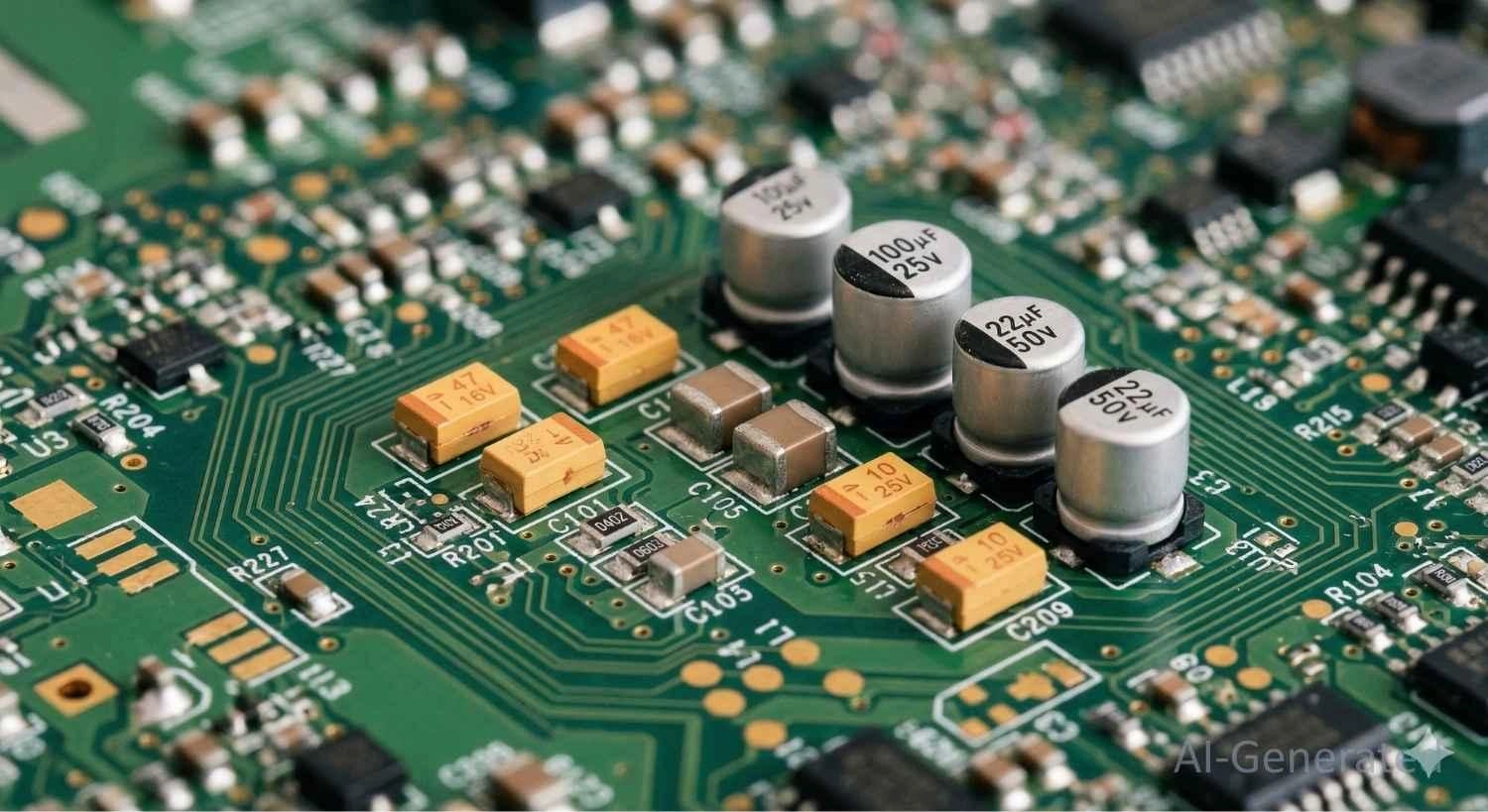
Figure: A printed circuit board populated with different sizes of surface mount capacitors
SMD Capacitor Size Chart for Fast Reference
Having a quick and reliable reference for surface-mount capacitor sizes is essential when doing schematic capture and PCB layout. The tables below break down the standard dimensions for the most common capacitor technologies.
SMD Multilayer Ceramic Capacitor Package Sizes (MLCC)
Multi-Layer Ceramic Capacitors (MLCCs) are the most frequently used surface-mount capacitors. They follow standardized EIA (Electronic Industries Alliance) codes.
EIA Code (Imperial) | Metric Code | Length (L) mm | Width (W) mm | Length (inches) | Width (inches) |
|---|---|---|---|---|---|
01005 | 0402 | 0.40 ±0.02 | 0.20 ±0.02 | 0.016" | 0.008" |
0201 | 0603 | 0.60 ±0.03 | 0.30 ±0.03 | 0.024" | 0.012" |
0402 | 1005 | 1.00 ±0.05 | 0.50 ±0.05 | 0.040" | 0.020" |
0603 | 1608 | 1.60 ±0.10 | 0.80 ±0.10 | 0.063" | 0.031" |
0805 | 2012 | 2.00 ±0.20 | 1.25 ±0.20 | 0.079" | 0.049" |
1206 | 3216 | 3.20 ±0.20 | 1.60 ±0.20 | 0.126" | 0.063" |
1210 | 3225 | 3.20 ±0.20 | 2.50 ±0.20 | 0.126" | 0.098" |
1812 | 4532 | 4.50 ±0.30 | 3.20 ±0.30 | 0.177" | 0.126" |
2220 | 5750 | 5.70 ±0.40 | 5.00 ±0.40 | 0.220" | 0.197" |
Table: A comprehensive SMD ceramic capacitor size chart showing standard EIA Imperial package codes.
SMD Electrolytic Capacitor Size Codes
Aluminum electrolytic capacitors in surface-mount formats use "Case Codes" that denote the diameter and height of their cylindrical cans.
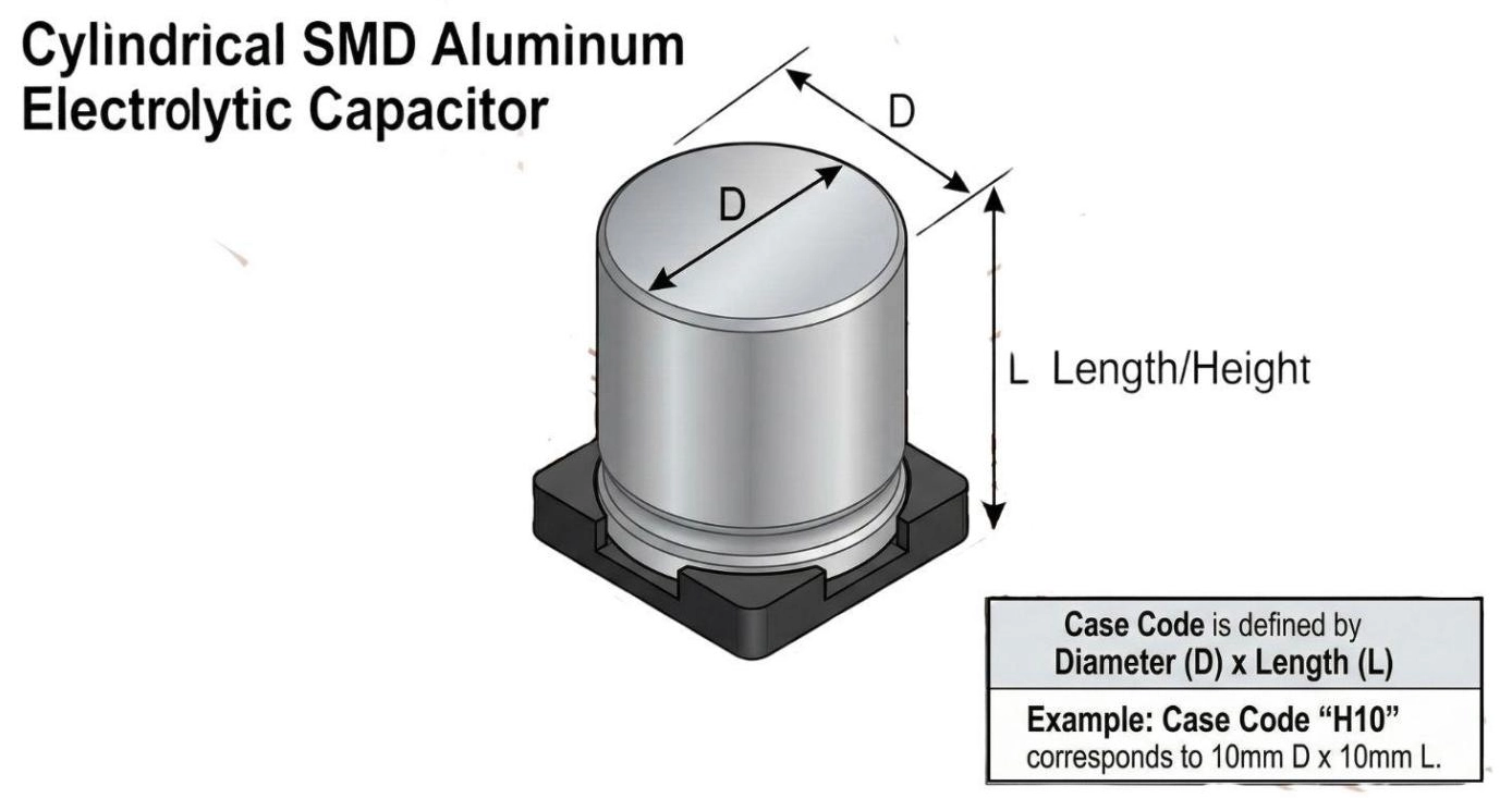
Figure: An SMD aluminum electrolytic capacitor showing how diameter and height correspond to its case code.
Case Code | Diameter (D) mm | Height (L) mm |
|---|---|---|
A | 4.0 | 5.4 |
B | 5.0 | 5.4 |
C | 6.3 | 5.4 |
D | 6.3 | 7.7 |
E | 8.0 | 6.2 |
F | 8.0 | 10.2 |
G | 10.0 | 10.2 |
H | 12.5 | 13.5 |
Table: SMD Electrolytic Capacitor size chart detailing standard case codes
SMD Tantalum Capacitor Size Charts
Tantalum capacitors are polarized and use a standardized letter system to define their footprints. To ensure proper orientation during placement, be sure to reference a capacitor polarity guide.
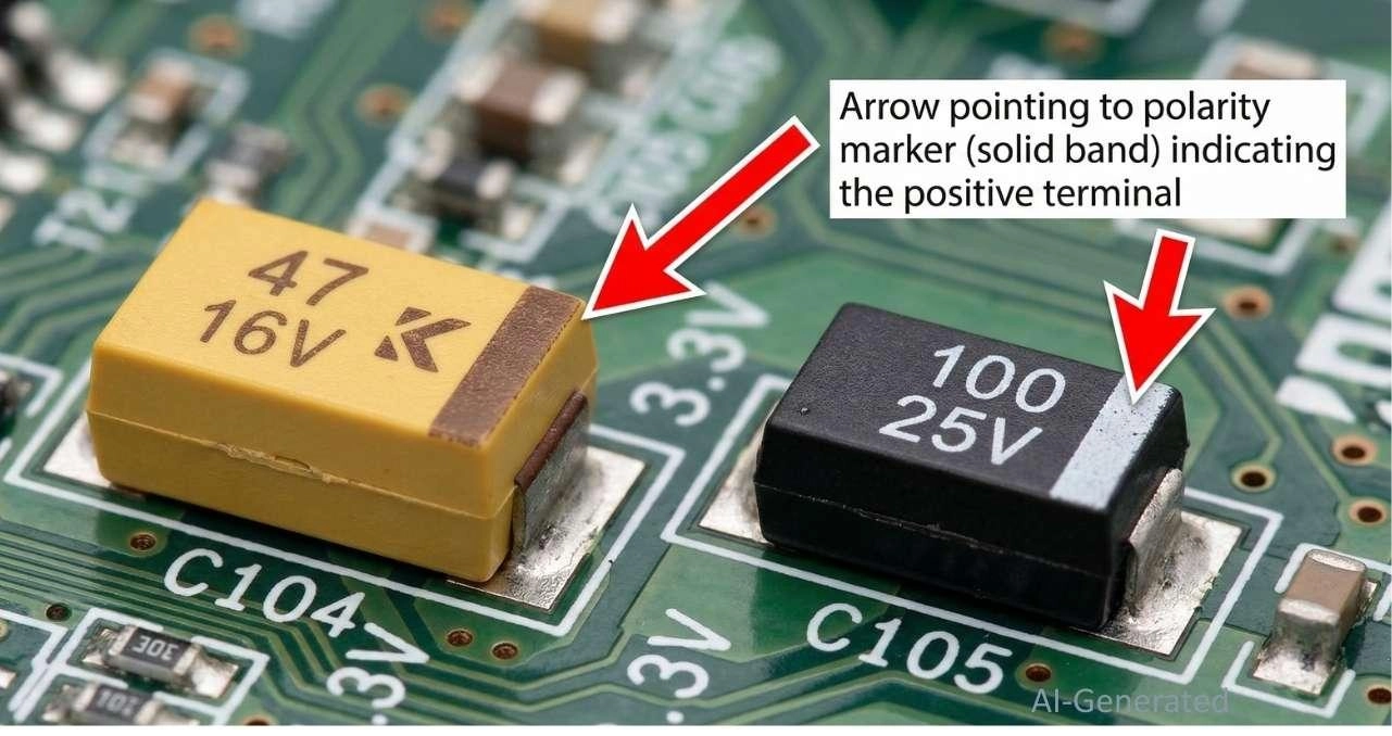
Figure: Examples of SMD tantalum capacitors in yellow and black resin cases, highlighting the distinct polarity band on the positive end.
Case Code | Metric Code | Length (mm) | Width (mm) | Height (mm) |
|---|---|---|---|---|
A | 3216-18 | 3.2 | 1.6 | 1.6 |
B | 3528-21 | 3.5 | 2.8 | 1.9 |
C | 6032-28 | 6.0 | 3.2 | 2.5 |
D | 7343-31 | 7.3 | 4.3 | 2.8 |
E | 7343-43 | 7.3 | 4.3 | 4.1 |
Table: SMD Tantalum Capacitor size chart listing EIA case codes with their corresponding metric codes and dimensions for length, width, and height in mm.
Visual Comparison of SMD Capacitor Sizes
Understanding the sheer scale of these components is vital. While a 1206 capacitor can easily be picked up with standard tweezers, a 0402 is barely larger than a grain of sand, and a 0201 is nearly invisible to the naked eye.
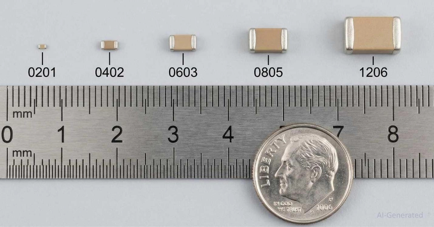
Figure: Visual comparison of common SMD capacitor sizes from 0201 to 1206 placed next to a metric ruler and a coin to demonstrate physical scale.
What Do SMD Capacitor Size Codes Mean?
What “SMD Capacitor Size” Means
When engineers refer to an "SMD size" or "package size," they are strictly talking about the physical dimensions (length and width) of the component's body. This physical footprint dictates the land pattern (solder pads) required on the printed circuit board.
How Capacitor Package Sizes Are Defined (EIA Standard)
The standard naming convention groups the length and width into a four-digit number. For example, an 0805 capacitor means its dimensions are roughly 0.08 inches in length by 0.05 inches in width.
Imperial vs Metric Capacitor Size Codes
A common trap for young players is the confusion between Imperial (EIA) and Metric sizing. Because both systems use four-digit codes, catastrophic design errors can occur if you mistake one for the other.
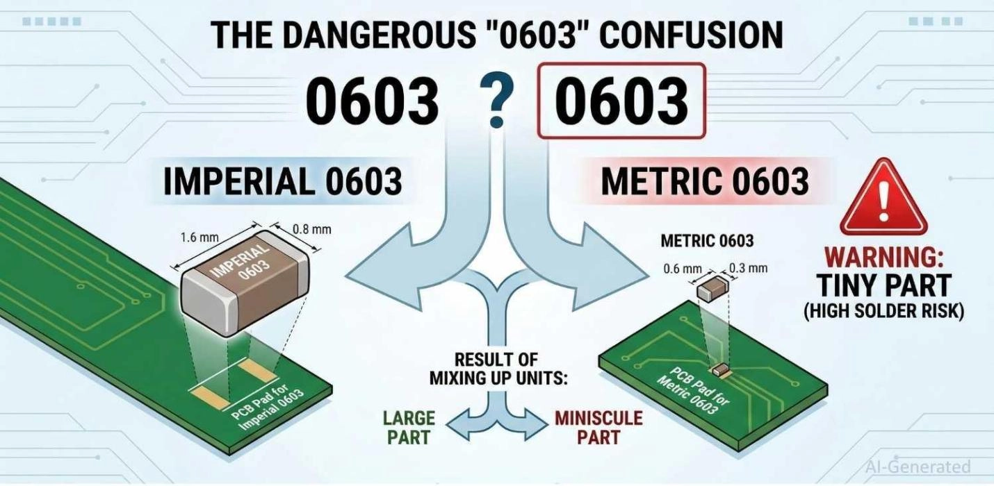
Figure: Infographic explaining the dangerous difference between an Imperial 0603 capacitor size and a Metric 0603 capacitor size.
- Imperial 0603: 0.06" × 0.03" (1.6mm × 0.8mm) - The industry standard.
- Metric 0603: 0.6mm × 0.3mm (0.024" × 0.012") - This is actually an Imperial 0201!
Rule of thumb: Unless otherwise specified, US and global EDA tools generally default to Imperial codes when referencing SMD capacitor sizes.
Common SMD Capacitor Sizes Explained in Electronics
Which SMD capacitor sizes are most commonly used in day-to-day engineering?
Here is a quick reference:
- 0201 Capacitor Size: Ultra-miniature. Primarily used in smartphones, IoT devices, and wearable PCB assembly, where every millimeter counts.
- 0402 Capacitor Size: Highly popular in modern, dense consumer electronics. It requires precise reflow soldering but saves substantial board space.
- 0603 Capacitor Size (Most Common): The undisputed "sweet spot." It balances small size with ease of handling. It is highly recommended for fast and easy prototype PCB assembly.
- 0805 Capacitor Size: Very easy to hand-solder. Frequently used for decoupling, higher power circuits, and bulk capacitance.
- 1206 Capacitor Size: Larger package often reserved for high-voltage applications or specific analog filtering needs.
- Larger Capacitors (1210, 1812, 2220): These are bulky and usually reserved for power supplies, motor drivers, or specialized high-capacitance, high-voltage requirements.
How to Choose the Right SMD Capacitor Size for Your Project
Selecting the exact footprint goes beyond just fitting components onto a board. Consider these four pillars:
PCB Space Constraints
If you are designing a high-density board, you will inevitably need to step down to 0402 or even 0201 sizes to route all your traces effectively.
Electrical Performance Requirements
As capacitance values go up, so does the required package size (for a given voltage). You simply cannot find a 100μF 50V ceramic capacitor in a 0402 package; the physics of the dielectric layers demand a much larger 1210 or electrolytic package.
Thermal and Power Handling
Larger capacitor sizes (like 1206 and 1210) have more mass and surface area, allowing them to dissipate heat better. They are inherently better suited for high-ripple-current environments like switching power supplies.
Manufacturing and Assembly Considerations
If you are hand-soldering your prototypes, stick to 0805 or 0603. Sizes like 0402 and 0201 generally require solder paste, a stencil, and a reflow oven.
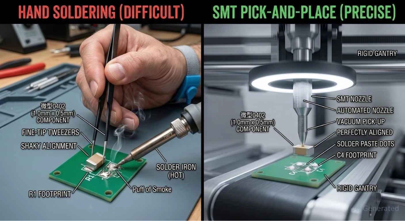
Figure: Split visual comparing the difficulty of hand soldering tiny SMD components versus the precision of an automated SMT pick-and-place machine.
From SMD Capacitor Sizes Selection to Reliable PCB Assembly
When engineers choose an SMD capacitor size, their ultimate goal is to move from a CAD file to a physical, working product. This is where reliable PCB assembly steps into the spotlight.
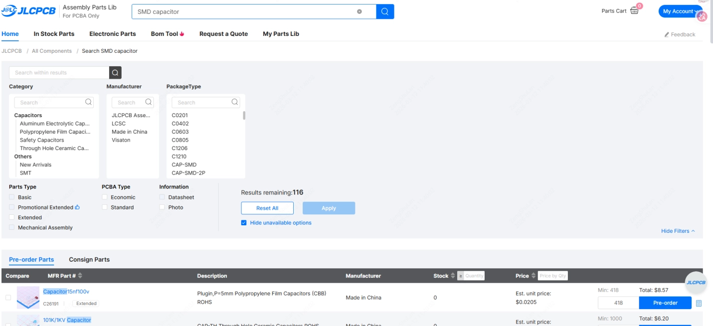
As you transition to low-volume PCB assembly, choosing standard capacitor sizes directly affects your bottom line. By selecting common sizes (0402, 0603, 0805), you guarantee component availability. JLCPCB's massive Parts Library maintains millions of standard SMD capacitors in stock, meaning you avoid costly sourcing delays.
Furthermore, you don't need to fear utilizing smaller packages. JLCPCB provides top-tier automated SMT assembly that seamlessly supports ultra-miniature 0201 components. Whether you are building an IoT wearable or scaling a dense industrial board, JLCPCB's PCB Assembly services ensure perfect placement and robust solder joints, allowing you to design with confidence.

SMD Capacitor Sizes and PCB Design Rules
To guarantee a defect-free board, your CAD layout must match strict design rules corresponding to your chosen capacitor size.
Typical PCB Footprint Dimensions
Never guess the pad sizes. Always follow the IPC-7351 standard or the specific manufacturer's datasheet. A footprint for a 0603 component requires the pads to be slightly wider and longer than the component itself to allow the solder fillet to form.
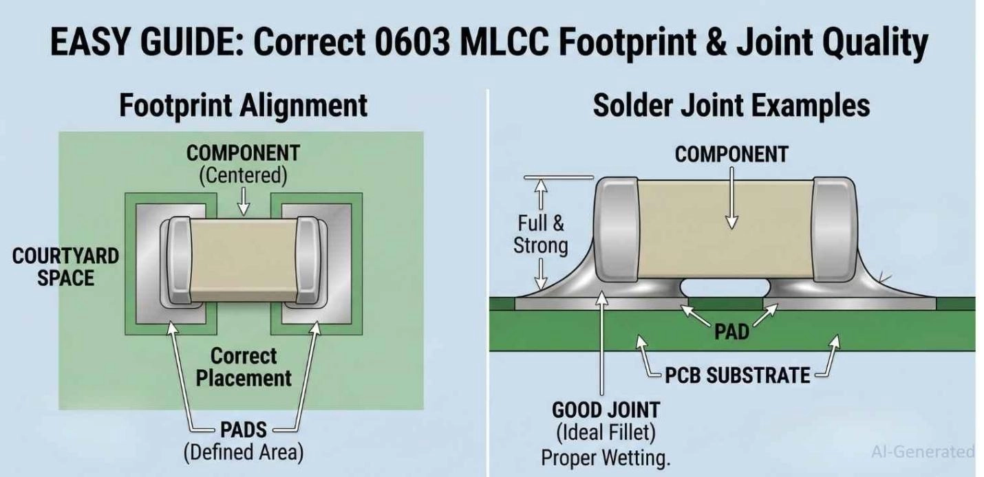
Figure: Annotated diagram illustrating the correct PCB footprint and solder pad dimensions for a 0603 SMD capacitor, showing ideal solder fillet formation.
Solder Mask and Pad Design
Proper solder pad design dictates that your solder mask expansion should provide enough web between the two pads of the capacitor. If the gap between the pads on a 0402 component lacks solder mask, you drastically increase the risk of solder bridges.
Preventing Tombstoning in Small Capacitors
Tombstoning is a severe defect where a component stands on one end during reflow. It heavily affects 0402 and 0201 sizes. To prevent this:
- Ensure the two solder pads are perfectly symmetrical.
- Make sure thermal reliefs are used if one pad connects to a large ground plane.
- Use a high-quality solder paste.
Figure: Diagram demonstrating the tombstoning effect during PCB reflow soldering, where an SMD capacitor stands vertically due to unequal thermal mass and solder tension.
How SMD Capacitor Size Affects Capacitance, Voltage, and Performance
Why Larger Capacitors Support Higher Capacitance
Capacitance is dictated by the area of the internal parallel plates and the thickness of the dielectric. A larger physical package (like 1210) allows manufacturers to stack hundreds more layers inside, dramatically increasing the capacitance value.
Size vs Voltage Rating
To increase a capacitor's voltage rating, the dielectric layers between the internal plates must be thicker to prevent arcing. Thicker layers mean fewer layers can fit in a small package. Thus, high-voltage capacitors naturally require larger packages like 1206 or 1812.
Size vs ESR and Frequency Performance
In high-frequency applications, the physical length of the capacitor acts as a tiny inductor (ESL - Equivalent Series Inductance). Smaller packages like 0402 have lower ESL than 1206 packages, making small capacitors significantly better bypass capacitors for high-speed ICs.
DC Bias Effects
This is a critical, often-overlooked phenomenon in MLCCs. As you apply DC voltage across a ceramic capacitor, its effective capacitance drops. This drop is much more severe in smaller package sizes. A 10μF 0603 capacitor might drop to 3μF under a 5V load, whereas a 10μF 1206 capacitor might retain 8μF.
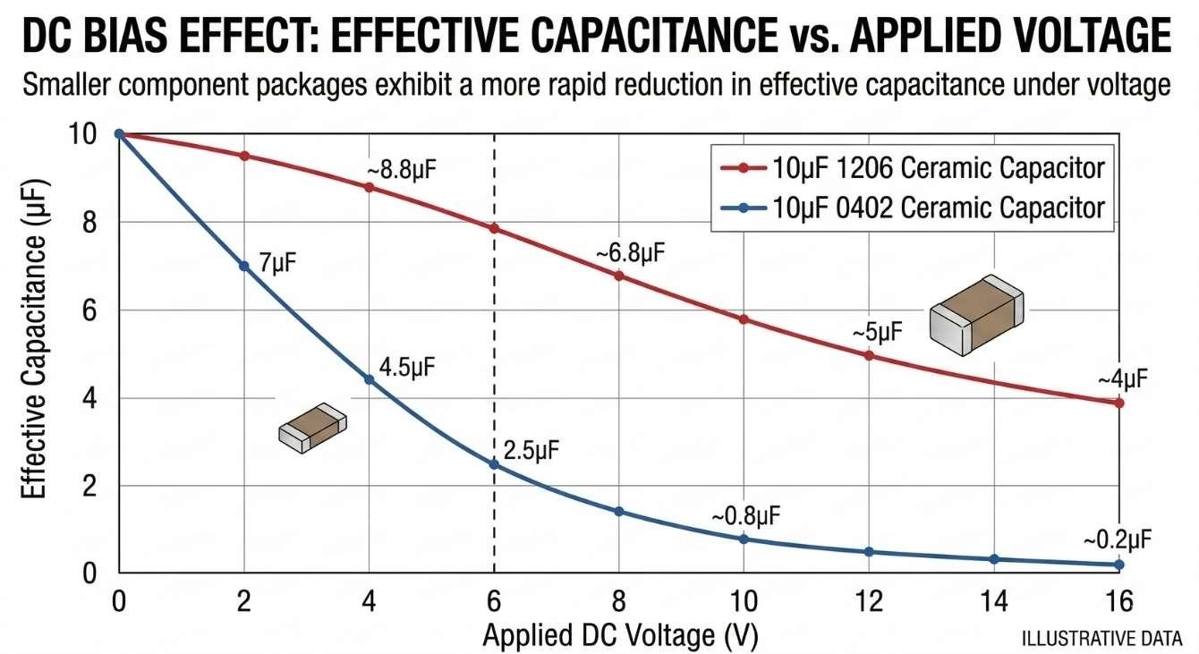
Figure: A graph illustrating the DC bias effect, showing how smaller SMD capacitor packages lose their effective capacitance much faster under voltage load compared to larger packages.
Common Mistakes When Selecting SMD Capacitor Sizes
Choosing Capacitors Too Small for Manual Assembly
If you intend to prototype a board by hand, selecting 0201 or 0402 is a recipe for frustration. Ensure your package size matches your assembly method. Stick to 0603/0805 for manual irons or basic hot air.
Ignoring Voltage Derating
Engineers sometimes pick a 10V-rated 0402 capacitor for a 9V rail to save space. A standard engineering practice is to derate capacitors by 50% - meaning for a 9V rail, you should use at least a 16V or 25V capacitor, which may force you to size up to a 0603.
Not Considering DC Bias Effects
Replacing an 0805 decoupling capacitor with a 0402 of the same stated value, without checking the DC bias charts. Your circuit may become unstable because the smaller capacitor's real-world capacitance is much lower under operational voltage.
FAQs
Q: What are common SMD capacitor sizes?
The most common imperial sizes for general electronics are 0402, 0603, and 0805.
Q: How to choose an SMD capacitor package?
Base your decision on available board space, the required capacitance/voltage ratings, the specific DC bias characteristics of the package, and whether the board will be hand-soldered or machine-assembled.
Q: Is it better to oversize or undersize a capacitor?
When referring to physical size, oversizing is generally better for thermal dissipation, DC bias retention, and voltage derating, provided you have the PCB real estate.
Q: How to identify an SMD capacitor value?
Unlike SMD resistors, most MLCCs do not have printed markings. You must use an LCR meter, a multimeter, or refer to reading SMD capacitor codes if they are clearly marked on the reel packaging.
Q: How to check a capacitor size?
Use digital calipers to measure the length and width in millimeters, then convert to the nearest standard EIA code (e.g., 1.6mm × 0.8mm = 0603).
Q: Can I replace a 16V capacitor with a 50V capacitor?
Yes, replacing a lower voltage capacitor with a higher voltage one of the same capacitance is perfectly safe. However, the 50V capacitor will likely require a larger physical footprint.
Q: Can I use a 25V capacitor instead of 50V?
No, if the circuit operates near 50V, using a 25V capacitor will result in dielectric breakdown, causing a short circuit or explosion.
Q: What happens if you use the wrong size capacitor?
Physically, it will not fit the PCB footprints properly, leading to weak solder joints or tombstoning. Electrically, choosing a package too small might result in heavy capacitance loss due to DC bias.
Q: Can I use a 440v capacitor instead of a 250V?
Yes, for AC or high-voltage applications, using a capacitor rated for a higher maximum voltage is always safe, assuming the physical dimensions still fit your design constraints.
Conclusion
Understanding surface-mount capacitor sizes is a foundational skill for anyone working in electronics hardware. By referencing proper size charts and understanding the nuances behind voltage derating, DC bias, and footprint design, you can ensure your circuit performs perfectly in the real world.
Whether you are laying out a dense 0402 digital board or utilizing heavy 1210 capacitors for power regulation, the bridge between a good design and a great product is reliable manufacturing.
Take the hassle out of your next production run - get an instant PCBA quote at JLCPCB and experience seamless, high-quality automated assembly today.
Popular Articles
• SMD Diode Code Lookup: Full List, Marking Guide & Identification [2026 Guide]
• SMD Resistor Package Sizes: Complete Size Chart, Footprints & How to Choose
• SMD Capacitor Codes: Identification, Markings, and Polarity
• SMD Capacitor Sizes: Complete Size Chart and Selection Tips for PCB Design and Assembly
• How to Solder SMD Components Like a Pro [2026 Updated]
Keep Learning
PoP Package (Package on Package) Explained: Architecture, Assembly, and SMT Challenges
In the race for miniaturization, fitting more processing power into smaller footprints is the ultimate challenge for PCB designers. Package on Package (PoP) technology answers this by integrating logic and memory vertically, becoming the standard for modern mobile processors. However, this 3D architecture demands advanced SMT assembly capabilities beyond standard fabrication. JLCPCB specializes in the high-precision manufacturing required to master these complex stacks. This guide covers how PoP packa......
What Is a PQFP Package? Plastic Quad Flat Package Design, Footprint, and Assembly Guide
The Plastic Quad Flat Package (PQFP) is a widely used IC package in industrial, automotive, and embedded designs. This article provides a practical, engineering-focused guide to PQFP package. It explains how PQFP is built, when it makes sense to use it, how it compares with newer package types, and what designers should consider in terms of footprint design, thermal performance, signal integrity, manufacturing, and reliability. What Is a PQFP Package (Plastic Quad Flat Package)? A Plastic Quad Flat Pa......
Small Outline Integrated Circuit (SOIC): Package, Specs & Uses
As designs transition from legacy through-hole components to high-density Surface Mount Technology (SMT), the Small Outline Integrated Circuit (SOIC) remains the industry standard for operational amplifiers, flash memory, sensors, and microcontrollers. It stands as a testament to balanced engineering, offering a perfect compromise between the miniaturisation demanded by modern consumer electronics and the ruggedness required for industrial applications. This article serves as a definitive engineering ......
A Complete Guide to Surface Mount Device (SMD)
Imagine holding a smartphone in your hand. Inside that sleek device lies a complex network of thousands of miniature components — resistors smaller than a grain of rice, capacitors thinner than a fingernail, and integrated circuits containing millions of transistors. Without Surface Mount Technology (SMT) and its compact Surface Mount Devices (SMDs), none of this would exist. Just a few decades ago, electronics were bulky. Radios filled desks, computers filled rooms, and assembling a circuit meant dri......
Circuit Breaker Types Explained: MCB, MCCB, RCCB, RCBO, ACB, VCB & SF6 Circuit Breakers
A circuit breaker automatically disconnects power when it detects faults such as overloads or short circuits, protecting equipment and reducing fire risk. Different circuit breaker types are designed for different voltage levels, current ratings, and applications, from household distribution boards to high-voltage substations. This guide explains the most common types - including MCBs, MCCBs, RCCBs, RCBOs, ACBs, VCBs, and SF6 breakers and helps you choose the right one for your application. Figure: Ci......
Quad Flat Package (QFP): The Engineer's Guide to Design, Assembly and Thermal Management
What is QFP Package? The Quad Flat Package (QFP) is one of the most popular surface mount technology (SMT) package formats throughout the history of electronic manufacturing. After it became standard in the 1980s, the QFP has been the industry standard for integrated circuits (ICs) with moderate to high pin counts that typically range from 32 to 304 pins, so it was a good alternative for simple SOIC packages and complex Ball Grid Arrays (BGAs) at the same time. Defined by its "gull-wing" leads extendi......