This website requires JavaScript.
Coupons Download APP
Ship to

What is an FR4 PCB?

Flame Retardant 4, or FR4, is a material grade used in PCB manufacturing. It is made of fibreglass and "4" represents the UL94 V-0 flammability standard (it must self-extinguish after being ignited). Fibreglass reinforced woven glass fibre and epoxy resin with makes it excellent for electrically insulated applications. FR4 is a widely used material due to its low cost and high reliability.

FR4 Material Overview

FR4 represents flame-retardant grade 4 glass-reinforced epoxy laminate. The material's dielectric constant and dissipation factor (loss tangent) are moderate. FR4 can be used in low-speed and high-power applications, making it the first choice for many hobbyists. This makes it suitable for general-purpose electronic designs.

Dielectric constant: around 4.5 at 1MHz (moderate). Loss tangent: around 0.02 at 1MHz (moderate). The glass transition temperature (Tg) determines how the material behaves under heat. It is one of the most important thermal properties in the classification of FR4 materials.

FR4 comes in three different temperature ranges:
  • Low Tg (130–140°C)
  • Standard Tg (150–160°C)
  • High Tg (>170°C)
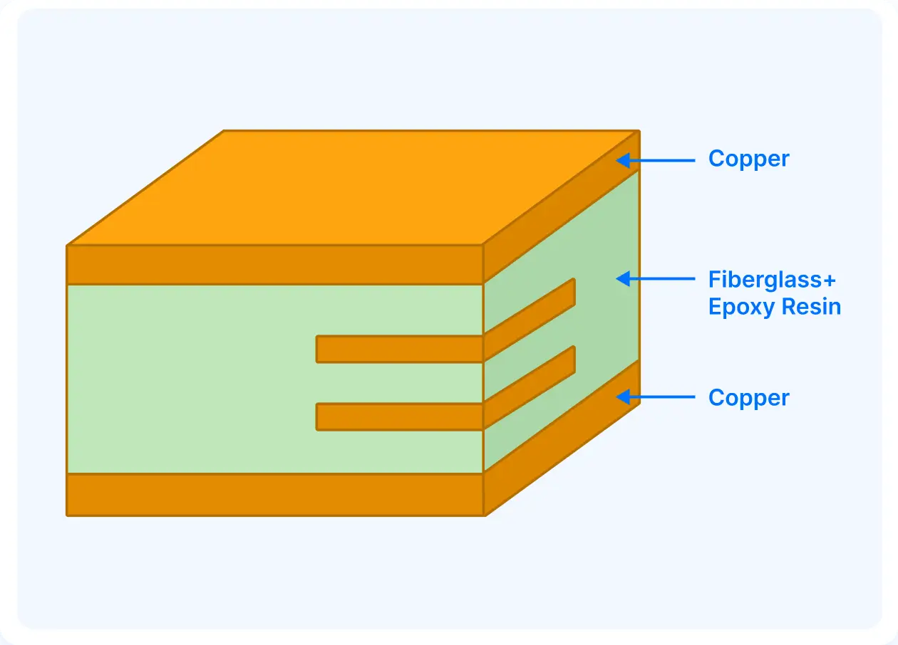
fr4 pcb substrate composition with copper foil layers

Structure and Properties of FR4

FR-4 is a composite material used as the substrate in PCBs. Its structure is made from:
1. Woven Fiberglass Cloth (E-glass fibers): Fibreglass provides higher mechanical strength and appears as a fine woven fabric inside the laminate.
2. Epoxy Resin (flame-retardant, brominated): Epoxy acts as the matrix, binding the fiberglass together and providing excellent electrical insulation and thermal resistance.
3. Copper Foil (in PCBs): Copper foil layers are used to make tracks and are laminated onto FR-4 using heat and pressure.

Benefits of FR4 PCB Material

Cost-Effective and Widely Available

FR-4 is affordable compared to advanced laminates like Rogers. Its low cost makes it popular and the industry standard for most applications. It is globally available, making it easy to source for large production volumes.

Good Mechanical Strength

The woven fiberglass provides higher tensile strength, making it more resistant to warping, bending, and mechanical stress.

Reliable Electrical Insulation

Due to a moderate dielectric constant, it is excellent for low-frequency and higher-power applications. Additionally, the epoxy-fiberglass structure offers higher signal isolation.

How FR4 Thickness Affects PCB Performance
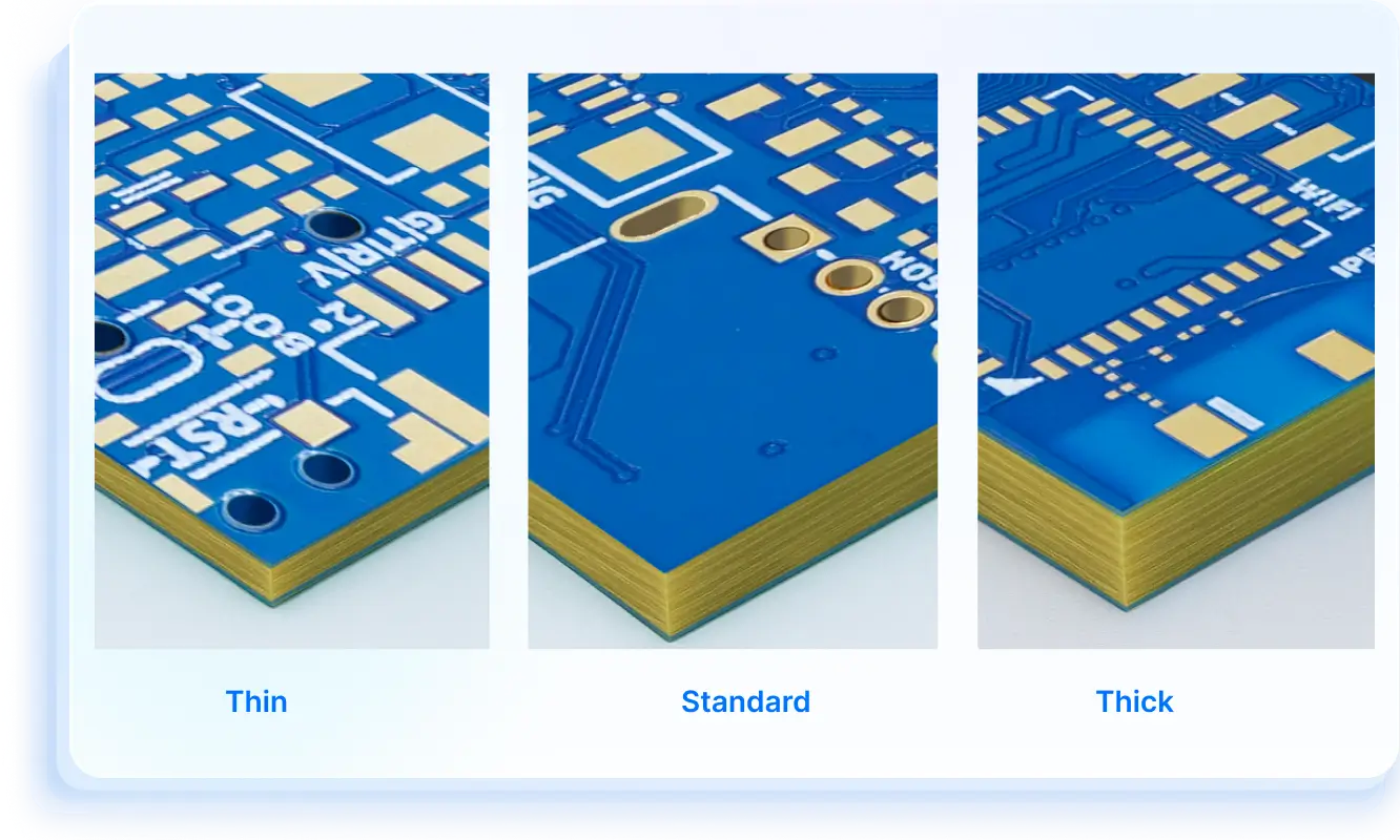
fr4 pcb thickness variations impact on performance

Signal Integrity and Impedance Control

  • Thicker FR-4 increases the dielectric spacing, which raises impedance by introducing parasitic components. FR-4 thickness can be adjusted to control impedance for different circuit applications.
  • Thinner FR-4 has a smaller dielectric spacing between copper layers, which lowers the impedance of traces. However, the higher dielectric loss of FR-4 limits performance above a few GHz regardless of thickness.

Thermal Management

Mechanical Stability

Common Applications of FR4 PCBs

Consumer Electronics

  • FR4 PCBs balance cost and strength for everyday electronic devices. From smartphones to wearables, FR-4 provides durable and reliable PCB solutions.

Industrial Control Systems

Automotive Electronics
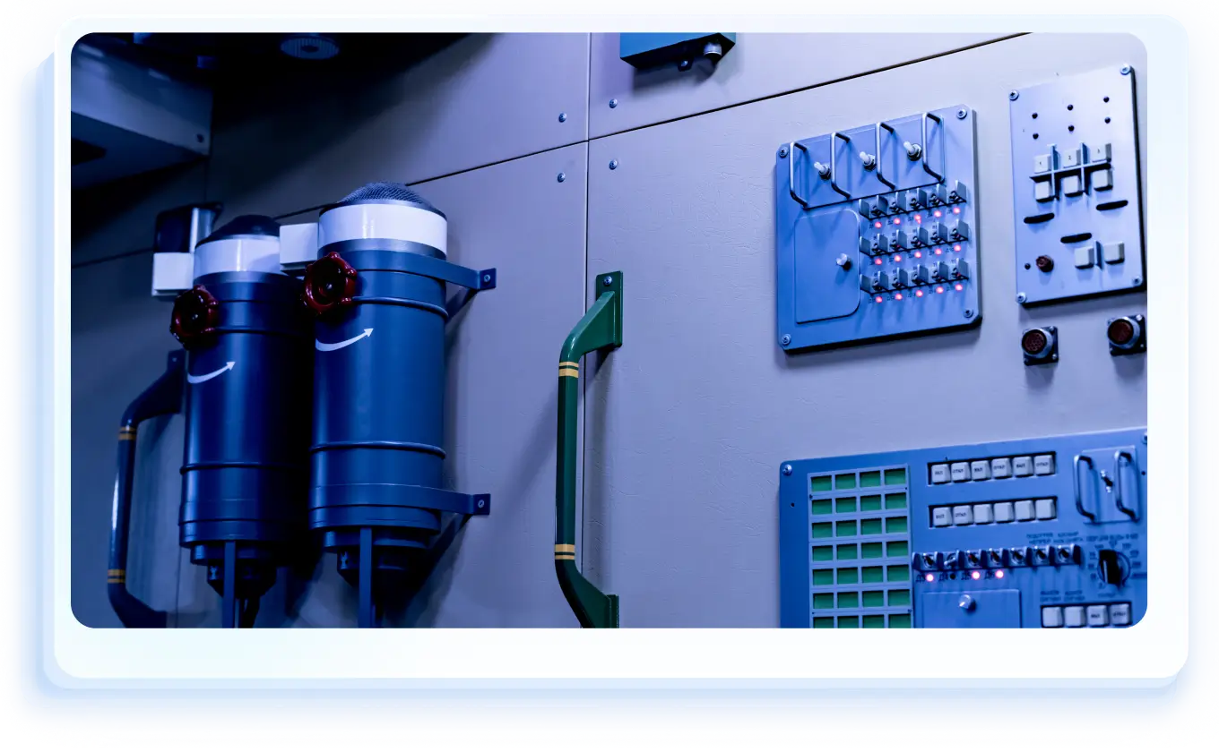
jlcpcb fr4 pcb application in industrial control systems

JLCPCB FR4 PCB Manufacturing Capabilities

Features
Capabilities
Layer count

1, 2, 4, 6, ...32 layers

Controlled Impedance

4/6/8/10/12/14/16/18/20/.../32 layers

User Guide to the JLCPCB lmpedance Calculator

Impedance Tolerance

±10% (±5Ω if value ≤ 50Ω)

UL Number
Maximum Dimensions

670 × 600mm (Thickness ≥ 0.8mm);

500 × 600mm (Thickness < 0.8mm);

2-layer reaches 1020 × 600mm.

Minimum Dimensions

3 × 3mm; 70 × 70 for V-cut panel

Outer Copper Thickness

1oz, 2oz (2.5oz, 3.5oz, 4.5oz for 2-layer)

Inner Copper Thickness

0.5 oz, 1 oz, 2 oz

Surface finish

HASL (leaded / lead-free), ENIG(1u" / 2u")

Minimum Via Hole/Diameter

0.15mm / 0.25mm

Hole Size Tolerance

① Plated: Through-holes: +0.13 / -0.08mm ; Press-fit holes:±0.05mm

② Non-plated: ±0.2mm

Minimum Plated Slots

0.5mm

Minimum Non-Plated Slots

1.0mm

Plated Edges

Available with PCB size 10 × 10mm, thickness: 0.6mm. ENIG is required.

PCB Design Instructions for Edge Plating

Blind Slot

Available in 2-32 layer boards with a thickness of ≥ 0.8mm.

Countersink Hole

Available in 2-32 layer boards with a thickness of ≥ 0.6mm.

Supported countersink angle: 90°/135°

Backdrill

Available in 4-32 layer boards with a thickness of ≥ 0.8mm.

Holes will be epoxy resin filled after backdrilling.

Castellated Holes

Available with PCB size 10 × 10mm.

Minimum Track Width and Spacing

① 1oz: 0.10 / 0.10mm (4 / 4mil) for 1/2-layer ; 0.09 / 0.09mm (3.5 / 3.5mil) for muliti-layer

② 2oz: 0.16 / 0.16mm (6.5 / 6.5mil) for 1/2-layer; 0.16 / 0.20mm (6.5 / 8mil) for multi-layer

Minimum BGA Pad Diameter

0.25mm

Gold Fingers Bevelling

30° or 45°

Why Choose JLCPCB FR4 PCBs?

Cost-Effective Production

FR4 PCBs starting from just $2, trusted by 6M+ customers worldwide, with over 50,000 new designs manufactured daily.

Extensive Capability

Supports 1–32 layers, board thickness from 0.2mm to 3.2mm, and copper weights up to 3oz.

High Customization

Pick from 7 solder mask colors, multiple finishes, and copper thickness options to fit any project.

Fast & Global Delivery

Prototypes in as fast as 24 hours, shipped to over 200 countries worldwide.

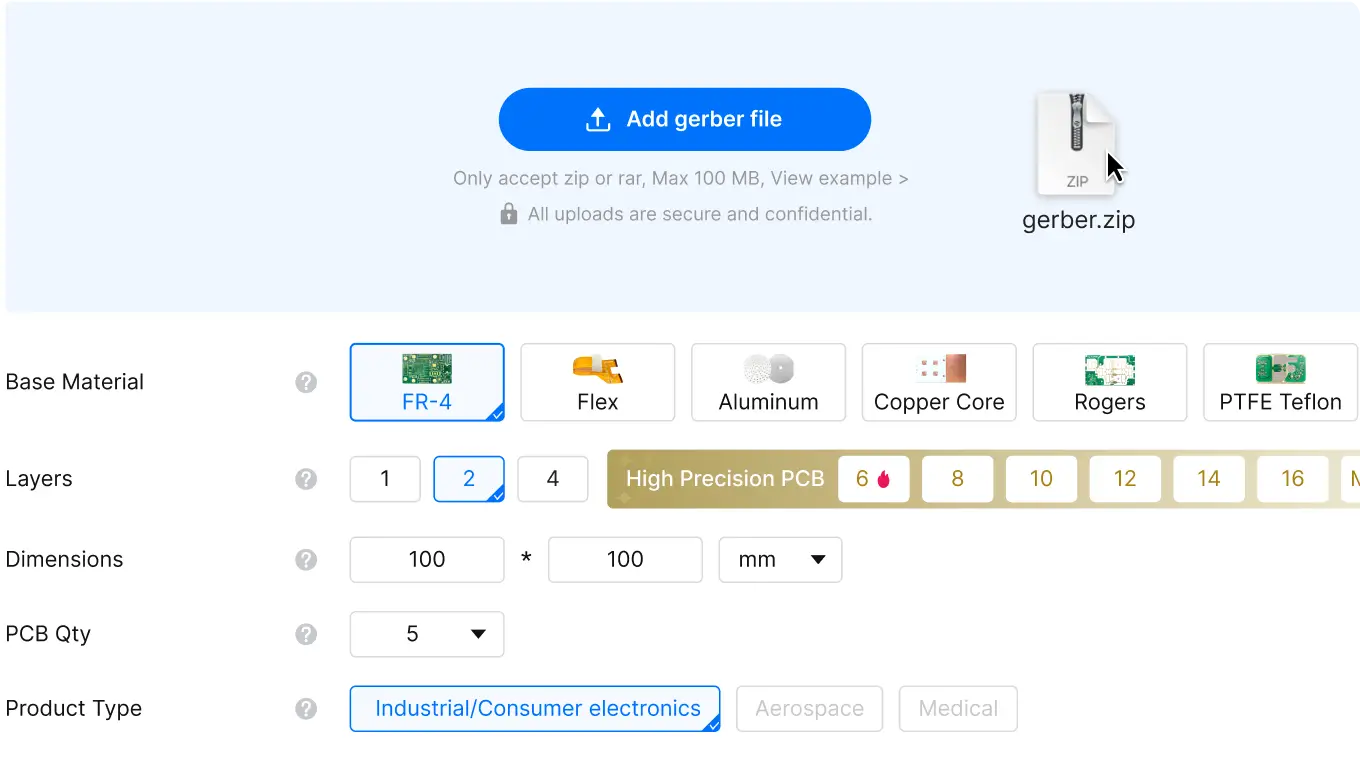
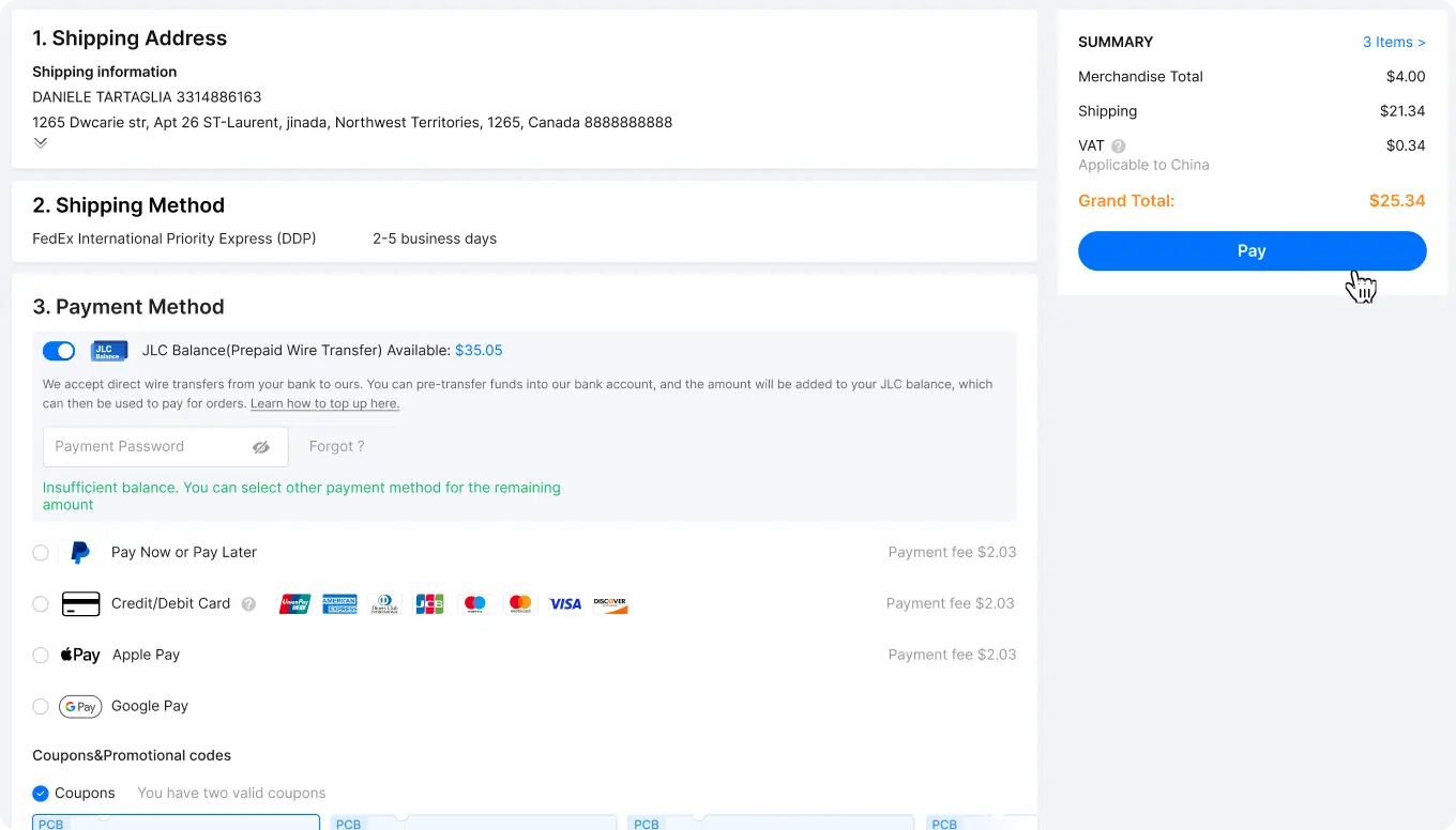
How to Order JLCPCB FR4 PCBs in 3 Easy Steps

jlcpcb advanced pcb manufacturing and assembly services

Frequently Asked Questions About FR4 PCB

What is the dielectric constant (Dk) of FR4 material?

FR4 typically has a dielectric constant of around 4.2–4.8 at 1 MHz. This property affects signal transmission speed and impedance control, making it an important factor in high-speed and RF designs.

What is the glass transition temperature (Tg) of FR4?

Is FR4 suitable for high-frequency circuits?

How does FR4 perform in multilayer PCB designs?

Are FR4 PCBs RoHS compliant and environmentally safe?

How does PCB material FR4 compare with other PCB substrates?

What Customers Say About JLCPCB FR4 PCBs

29****2A
FR4 2-layer
29****2A July 20, 2026
FR-4, 2 layer, Green, HASL(with lead), PCB Prototype
Another good reliable set of pcbs. Part of my dinoboards MSX retro computer kits for the RC2014 platform. A realtime clock module. Board's silkscreens always look good and make them very easy for the DIY hand soldering.
33****7A
FR4 2-layer
33****7A July 20, 2026
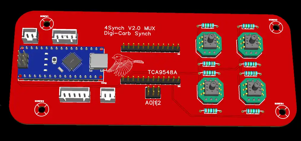
FR-4, 2 layer, Red, HASL(with lead), PCB Prototype
Digital radio receiver prototype, details coming soon on qrp.hu under the heading nanoRX. The continuation of the project can also be viewed and followed there. The manufactured printed circuit board is dimensionally accurate and matches the design precisely. All components and connectors fit perfectly into their intended positions. The holes and board outline are also manufactured with high precision. The copper traces are clean, uniform, and visually appealing. Overall, the PCB is of excellent manufacturing quality.
23****4A
FR4 2-layer
23****4A July 19, 2026
FR-4, 2 layer, Green, HASL(with lead), PCB Prototype
I’m very happy with the PCBs I received from PCBWay. The quality was great, everything looked exactly as expected, and the delivery was fast and smooth. I would definitely order from them again.
12*****4A
FR4 2-layer
12*****4A July 19, 2026
FR-4, 2 layer, Black, HASL(with lead), PCB Prototype
All the boards I have received looks high quality and indeed they worked well! I plan to make orders here in the future for new projects.

Unlock More Possibilities with JLCPCB Solutions

ordering and payment icon FR4 PCBs, Built Better with JLCPCB. Get Instant Quote bottom icon of webpage