
What Is an SMD Capacitor? A Complete Guide to Types, Sizes, Markings, and Applications
13 min
- What Are SMD Capacitors?
- Why SMD Capacitors Are Used in Modern Electronics
- SMD vs Through-Hole Capacitors: Key Differences
- Main Types of SMD Capacitors
- Understanding SMD Capacitor Sizes
- Understanding SMD Capacitor Markings and Codes
- Recognizing SMD Capacitor Polarity
- Advantages of SMD Capacitors
- Disadvantages and Limitations of SMD Capacitors
- Applications of SMD Capacitors in Electronic Circuits
- How to Choose the Right SMD Capacitor
- PCB Layout Best Practices for SMD Capacitors
- SMD Capacitors in Modern PCB Assembly
- FAQ about SMD Capacitors
- Conclusion
SMD capacitors are essential components in modern electronic circuits, enabling compact PCB design, high-frequency performance, and efficient automated manufacturing. As surface-mount technology has become the industry standard, understanding how these capacitors work and how to select them is crucial for engineers, students, and electronics enthusiasts.
In this guide, we will explore:
- What SMD capacitors are and how they differ from through-hole capacitors
- The main types of SMD capacitors and their electrical characteristics
- Standard package sizes and marking systems
- Polarity considerations and common identification methods
- Advantages and limitations in practical PCB design
- Typical applications in modern electronic circuits
- Key factors for choosing the right SMD capacitor
What Are SMD Capacitors?
An SMD capacitor is a capacitor specifically engineered for direct mounting onto the surface of a Printed Circuit Board (PCB).
Unlike traditional through-hole capacitors that feature long wire leads meant to be pushed through holes in the board and soldered on the reverse side, surface mount capacitors have no leads. Instead, they feature metalized terminations (end caps) that sit directly on corresponding copper pads on the PCB surface.
Structurally, the most common chip capacitors consist of alternating layers of conductive internal electrodes and insulating dielectric materials. During the manufacturing process, solder paste is applied to the PCB pads, the SMD capacitor is placed by an automated machine, and the entire board is passed through a reflow oven. The solder paste melts, forming a strong mechanical and electrical bond.
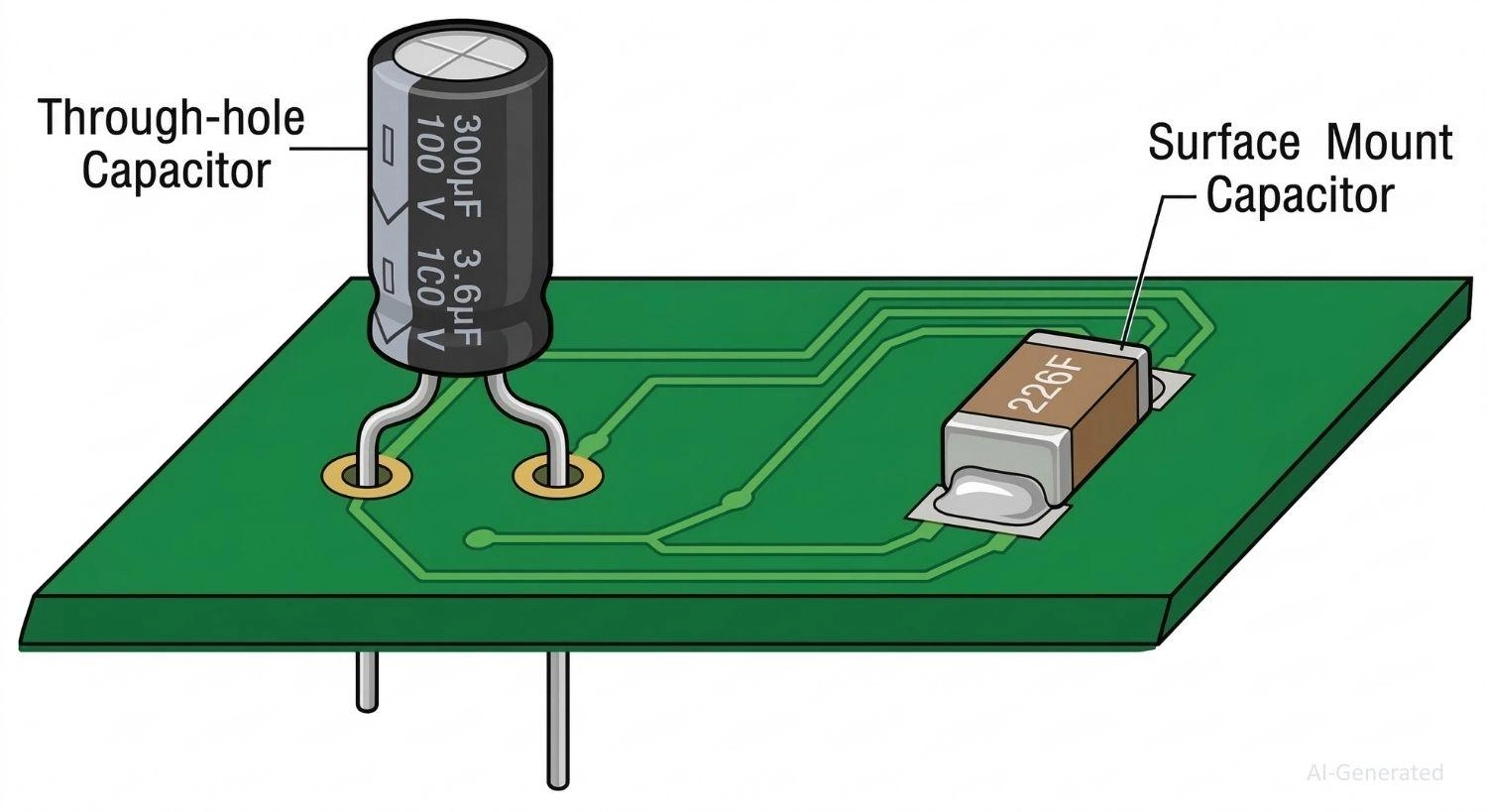
Figure: Comparison between a traditional through-hole capacitor and a surface-mount capacitor on a PCB.
Why SMD Capacitors Are Used in Modern Electronics
The dominance of SMD components over THT components is not just about size; it fundamentally changes how circuits perform and are manufactured.
- PCB Miniaturization: With packages shrinking down to 01005 (imperial) sizes, engineers can pack complex circuits into smartphones and IoT wearables.
- High-Speed Digital Design: Without long leads acting as tiny antennas, SMD capacitors possess significantly lower parasitic inductance. This is mandatory for high-speed microprocessors and RF circuits.
- Automated Manufacturing: SMT components are packaged in reels, allowing high-speed "pick-and-place" machines to populate thousands of parts per hour with extreme precision.
- Industry Demand: The automotive, telecommunications, and consumer electronics industries require lightweight, high-density, and highly reliable boards that only SMT can provide.
SMD vs Through-Hole Capacitors: Key Differences
To fully understand the shift to surface-mount technology, it is helpful to see exactly how SMD capacitors compare to their older THT counterparts. Here is a quick comparison table:
Feature | SMD Capacitor | Through-Hole Capacitor |
|---|---|---|
Mounting | Surface pads | PCB holes |
Size | Very compact | Larger |
Parasitic Inductance | Low | Higher |
Automated Assembly | Excellent | Limited |
Manual Prototyping | Difficult | Easy |
High-Frequency Performance | Better | Moderate |
Main Types of SMD Capacitors
Not all SMD capacitor types are created equal. The dielectric material heavily influences the component's capacitance range, voltage rating, and temperature stability.
SMD Capacitor Types Comparison
Capacitor Type | Capacitance Range | Typical Voltage | Key Characteristics & Best For |
|---|---|---|---|
Ceramic (MLCC) | 1 pF - 100 µF | 4V - 3kV+ | Non-polarized, very low ESR/ESL. Best for decoupling, high-frequency filtering. |
Tantalum | 1 µF - 1000 µF | 2V - 50V | Polarized, highly stable, high capacitance density. Best for bulk power filtering. |
Electrolytic (Aluminum) | 1 µF - 10 mF+ | 4V - 450V+ | Polarized, largest footprint. Best for heavy power supply smoothing. |
Film | 100 pF - 10 µF | 16V - 1kV | Non-polarized, extremely precise. Best for audio and timing circuits. |
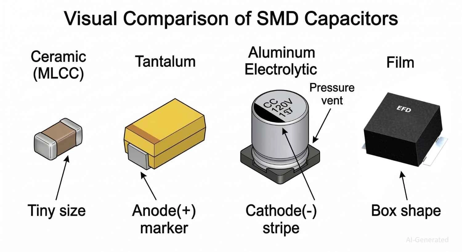
Figure: The four main types of SMD capacitors: Ceramic (MLCC), Tantalum, Aluminum Electrolytic, and Film
Ceramic SMD Capacitors (MLCC)
Multilayer Ceramic Chip Capacitors (MLCCs) account for the vast majority of SMD capacitors used today. They are broadly divided into two classes:
- Class 1 (e.g., C0G/NP0): Extremely stable across temperature and voltage changes. Used in precise timing circuits and RF applications.
- Class 2 (e.g., X7R, Y5V): Offer much higher capacitance in a smaller footprint but suffer from stability issues.
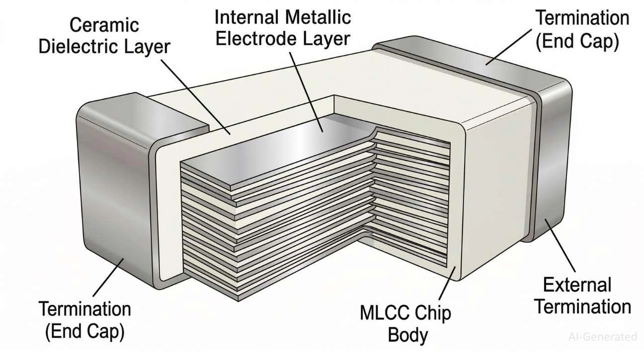
Figure: A Multilayer Ceramic Chip Capacitor (MLCC) internal structure.
Dielectric Class Characteristics: To select the right MLCC for your circuit, refer to this detailed breakdown of dielectric behaviors:
Dielectric | Stability | Capacitance Density | Temperature Behavior | Typical Use |
|---|---|---|---|---|
C0G/NP0 | Excellent | Low | Very stable | RF, timing |
X7R | Moderate | High | ±15% variance | Decoupling |
Y5V | Poor | Very high | -80% drift | Non-critical |
Engineering Tip: Be aware of the DC Bias Effect in Class 2 MLCCs; a 10µF X7R capacitor might only provide 3µF when operated near its maximum rated DC voltage. Furthermore, they can suffer from microphonics, acting like tiny piezoelectric speakers that induce noise under mechanical vibration.
Tantalum SMD Capacitors
Tantalum capacitors pack a massive amount of capacitance into a small footprint. They are highly stable over time and temperature compared to Class 2 ceramics. Newer polymer tantalum variants offer exceptionally low ESR (Equivalent Series Resistance).
Crucial Note: Standard tantalums are unforgiving. If subjected to severe overvoltage or reverse polarity, their failure mode is a violent short-circuit that can easily catch fire.
Aluminum Electrolytic SMD Capacitors
Easily identifiable by their cylindrical aluminum cans mounted on a square plastic SMT base, these are used when you need massive bulk energy storage (e.g., main power supply inputs). While they offer high capacitance, their high-frequency performance is poor compared to MLCCs.
Film SMD Capacitors
Though less common in SMT form due to their sensitivity to high reflow temperatures, film capacitors are highly prized for their zero-distortion characteristics, making them a staple in high-end audio crossovers, precision timing, and high-voltage snubber applications.
Understanding SMD Capacitor Sizes
To ensure compatibility with automated assembly, SMD capacitor packages are standardized by the EIA (Electronic Industries Alliance). Sizes are typically denoted by a four-digit code that represents the component's length and width.
Read more: SMD Capacitor Sizes: Complete Size Chart
Note: While the industry predominantly uses Imperial codes (inches), Metric codes (mm) are also used, which can occasionally confuse (e.g., Imperial 0603 vs. Metric 0603).
Imperial Code | Metric Code | Dimensions (L x W) mm | Typical Power/Voltage Impact |
|---|---|---|---|
0201 | 0603 | 0.6 x 0.3 | Ultra-compact, very low voltage, high-density boards. |
0402 | 1005 | 1.0 x 0.5 | Standard for smartphones and modern wearables. |
0603 | 1608 | 1.6 x 0.8 | Easy to hand-solder; common for general digital logic. |
0805 | 2012 | 2.0 x 1.2 | Good balance of higher capacitance/voltage ratings. |
1206 | 3216 | 3.2 x 1.6 | High voltage rating, excellent power dissipation. |
Larger packages (like 1206 or 1210) handle higher voltages and dissipate heat better, but are more susceptible to mechanical cracking when the PCB flexes.
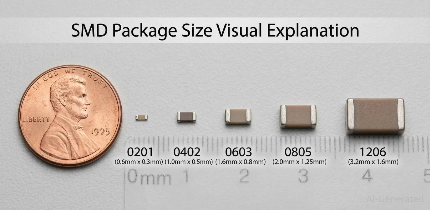
Figure: Visual size comparison of common SMD capacitor packages from 0201 to 1206.
Understanding SMD Capacitor Markings and Codes
Reading an SMD capacitor code can be tricky, depending on the component type.
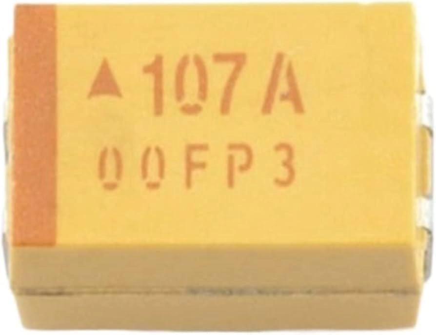
Figure: A tantalum capacitor marked 107A (Manufacturer's Code: 00FP3, 100µF, 10V Capacitor)
Manufacturer variations do exist. For a deeper dive into deciphering these alphanumeric systems and color bands, check out our comprehensive guide on how to read SMD capacitor codes.
Recognizing SMD Capacitor Polarity
Understanding SMD capacitor polarity is critical to avoiding catastrophic board failures.
- Ceramic and Film Capacitors: These are non-polarized. You can solder them in any orientation.
- Tantalum Capacitors: These are strictly polarized. They typically feature a solid dark line or a chamfered edge marking the Positive (+) terminal.
- Electrolytic Capacitors: These are also strictly polarized. The top of the aluminum can often features a colored half-circle or a bar, which usually indicates the Negative (-) terminal.
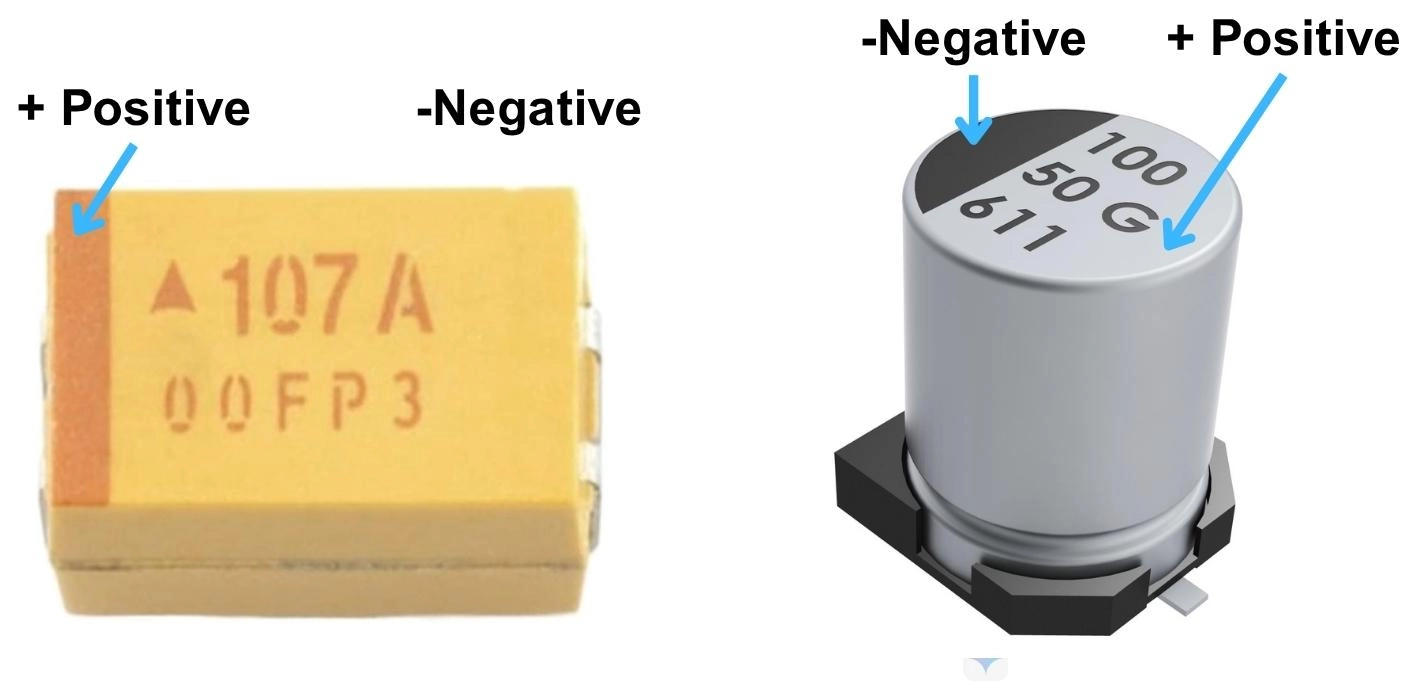
Figure: How to identify polarity on SMD Tantalum and Aluminum Electrolytic capacitors.
During PCB design, the footprint's silkscreen must clearly indicate polarity to ensure the pick-and-place machine correctly orients the component. Incorrect orientation of tantalums or electrolytics can lead to explosions, fires, and ruined PCBs. Learn more in our capacitor polarity guide.
Advantages of SMD Capacitors
- Lower ESL (Equivalent Series Inductance): The lack of wire leads to a drastic reduction in inductance. This makes SMD MLCCs exceptional at high-frequency decoupling, shunting fast-transient noise to ground before it interferes with sensitive ICs.
- High Placement Density: SMD components can be placed much closer together, allowing for shorter trace routing, which improves signal integrity.
- Automated SMT Assembly: Boards can be populated reliably and tested efficiently at massive scales, lowering overall production costs.
Disadvantages and Limitations of SMD Capacitors
While powerful, surface-mount capacitors do come with trade-offs:
- Difficult Manual Rework: Replacing a 0402 capacitor by hand requires a microscope, fine tweezers, and hot air rework stations.
- Mechanical Fragility: MLCCs are highly brittle. If the PCB flexes during panel separation or screw mounting, the ceramic can develop micro-cracks, leading to latent short-circuit failures.
- Voltage Constraints: It is difficult to manufacture high-voltage capacitors in ultra-small packages due to dielectric breakdown risks.
- Aging Effects: Class 2 ceramics (like X7R/Y5V) lose a percentage of their capacitance over time (aging), which must be factored into the circuit's lifespan calculations.
Troubleshooting Tip: If a board fails after physical stress (like being dropped), use a microscope to inspect the MLCCs near connectors and mounting holes for hairline cracks.
Applications of SMD Capacitors in Electronic Circuits
Due to their versatility, you will find surface-mount capacitors performing various critical roles:
How to Choose the Right SMD Capacitor
Choosing the correct capacitor goes far beyond picking a capacitance value. Use this quick reference table to match the capacitor type to your specific application:
SMD Capacitor Selection Quick Table
Application | Recommended Type | Key Parameter |
|---|---|---|
IC Decoupling | MLCC (X7R) | Low ESL |
Bulk Filtering | Tantalum / Electrolytic | High Capacitance |
RF Circuits | MLCC (C0G/NP0) | Stability |
Snubber | Film | High Voltage |
SMD Capacitor Selection Checklist
- Capacitance & Voltage Rating: Always apply a derating factor. If your rail is 12V, choose at least a 25V capacitor. Be highly aware of the DC bias derating in Class 2 ceramics.
- Ripple Current Rating: Crucial for power applications; exceeding it will cause the capacitor to overheat and fail.
- ESR vs. ESL Trade-off: Ensure the capacitor's impedance is lowest at the specific frequency of noise you are trying to filter.
- Reliability Class: If designing for harsh environments, filter your component search for Automotive grade (AEC-Q200) parts.
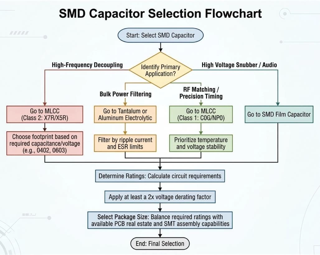
Figure: SMD Capacitor Selection Flowchart guiding the user from identifying the circuit application to choosing the dielectric and package size.
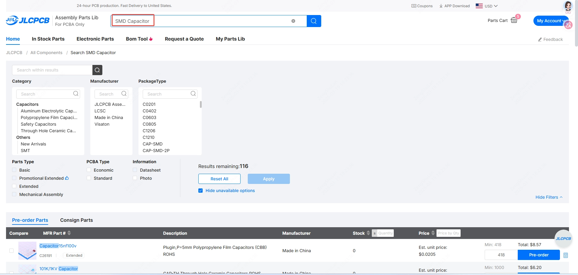
To ensure you are getting authentic, high-quality components for your designs, you can source reliable parts directly via the JLCPCB Parts library.
PCB Layout Best Practices for SMD Capacitors
Choosing the right capacitor is only half the battle; how you physically lay it out on the PCB determines its actual performance in the circuit. Follow these engineering guidelines for optimal results:
- Placement Near IC Power Pins: Decoupling capacitors must be placed as physically close to the target IC power pins as possible. The goal is to provide an instantaneous current during fast switching events before the main power supply can react.
- Minimizing Loop Area: A large routing loop between the IC power pin, the capacitor, and the ground pin creates parasitic inductance. A smaller decoupling capacitor loop area directly translates to better high-frequency noise suppression.
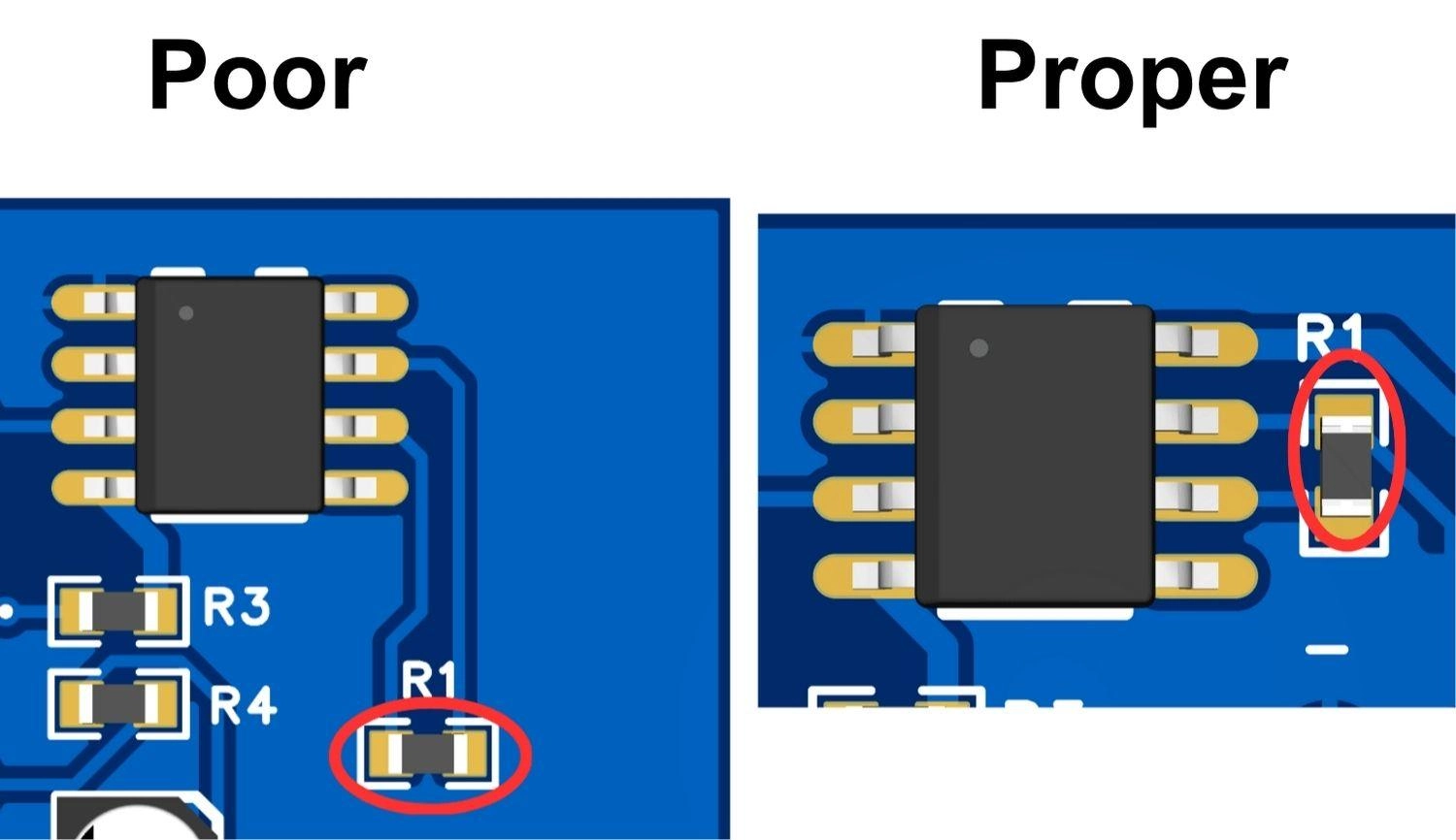
Figure: Good vs. Bad placement of a decoupling capacitor on a PCB.
- Via Inductance Management: When dropping connections to internal power or ground planes, place the vias as close to the SMD capacitor pads as manufacturing rules allow. To further slash parasitic via inductance, use two vias per pad rather than one.
- Solid Grounding Strategy: Always tie the capacitor’s ground pad to a solid, continuous internal ground plane. Avoid routing thin ground traces away from the capacitor, as this introduces impedance that ruins the decoupling effect.
SMD Capacitors in Modern PCB Assembly
Designing a great circuit is only half the battle; manufacturing it reliably is the other. Working with microscopic 0402 or 0201 packages introduces manufacturing challenges like component sourcing shortages, managing exact SMT stencil thicknesses, and ensuring precise reflow temperature profiles to avoid thermal shock.
PCB Assembly services like JLCPCB integrate high-quality component sourcing and automated SMT assembly, solving BOM challenges and ensuring perfect reflow profiles for microscopic components. Automated Optical Inspection (AOI) ensures that no capacitor is misplaced, tombstoned, or reverse-polarized.
By combining premium PCB Assembly services with instant quotations, engineers can accelerate their product development cycle from initial prototype to mass production with absolute confidence.
FAQ about SMD Capacitors
Q: Are SMD capacitors polarized?
Ceramic and film SMD capacitors are non-polarized. However, Tantalum and Aluminum Electrolytic SMD capacitors are strictly polarized and will fail catastrophically if installed backward.
Q: Why do MLCCs crack, and how can I prevent it?
They are made of brittle ceramic. Cracking usually happens when the PCB flexes during assembly, testing, or final housing installation. Prevent it by placing MLCCs parallel to the board's flex line and keeping them away from heavy mechanical stress points (like screws or v-scores).
Q: Can an SMD capacitor be replaced with a THT capacitor?
Electrically, yes, provided the specifications (capacitance, voltage, ESR) match. However, physically fitting a THT component onto an SMT pad is difficult and introduces parasitic inductance due to the long leads.
Q: What is ESR in capacitors, and why does it matter?
Equivalent Series Resistance (ESR) is the internal resistance of the capacitor. In high-power circuits, high ESR leads to unwanted heat generation and poor filtering efficiency.
Q: How do you read a capacitor value without markings?
Since most small MLCCs have no markings, the only reliable way to determine their value once removed from their reel is to desolder one leg from the circuit and test it using a precision LCR meter.
Conclusion
SMD capacitors are the unsung heroes of modern electronic design. By understanding the distinct characteristics of MLCCs, tantalums, and electrolytics, and by mastering the nuances of package sizes and polarity, you can design circuits that are more stable, compact, and efficient.
Combining proper capacitor selection, optimized PCB layout, and reliable SMT manufacturing ensures stable, high-performance electronic products.
With integrated PCB assembly services and component sourcing, platforms like JLCPCB help engineers move efficiently from prototype to production.
Popular Articles
• SMD Diode Code Lookup: Full List, Marking Guide & Identification [2026 Guide]
• SMD Resistor Package Sizes: Complete Size Chart, Footprints & How to Choose
• SMD Capacitor Codes: Identification, Markings, and Polarity
• SMD Capacitor Sizes: Complete Size Chart and Selection Tips for PCB Design and Assembly
• How to Solder SMD Components Like a Pro [2026 Updated]
Keep Learning
PoP Package (Package on Package) Explained: Architecture, Assembly, and SMT Challenges
In the race for miniaturization, fitting more processing power into smaller footprints is the ultimate challenge for PCB designers. Package on Package (PoP) technology answers this by integrating logic and memory vertically, becoming the standard for modern mobile processors. However, this 3D architecture demands advanced SMT assembly capabilities beyond standard fabrication. JLCPCB specializes in the high-precision manufacturing required to master these complex stacks. This guide covers how PoP packa......
What Is a PQFP Package? Plastic Quad Flat Package Design, Footprint, and Assembly Guide
The Plastic Quad Flat Package (PQFP) is a widely used IC package in industrial, automotive, and embedded designs. This article provides a practical, engineering-focused guide to PQFP package. It explains how PQFP is built, when it makes sense to use it, how it compares with newer package types, and what designers should consider in terms of footprint design, thermal performance, signal integrity, manufacturing, and reliability. What Is a PQFP Package (Plastic Quad Flat Package)? A Plastic Quad Flat Pa......
Small Outline Integrated Circuit (SOIC): Package, Specs & Uses
As designs transition from legacy through-hole components to high-density Surface Mount Technology (SMT), the Small Outline Integrated Circuit (SOIC) remains the industry standard for operational amplifiers, flash memory, sensors, and microcontrollers. It stands as a testament to balanced engineering, offering a perfect compromise between the miniaturisation demanded by modern consumer electronics and the ruggedness required for industrial applications. This article serves as a definitive engineering ......
A Complete Guide to Surface Mount Device (SMD)
Imagine holding a smartphone in your hand. Inside that sleek device lies a complex network of thousands of miniature components — resistors smaller than a grain of rice, capacitors thinner than a fingernail, and integrated circuits containing millions of transistors. Without Surface Mount Technology (SMT) and its compact Surface Mount Devices (SMDs), none of this would exist. Just a few decades ago, electronics were bulky. Radios filled desks, computers filled rooms, and assembling a circuit meant dri......
Circuit Breaker Types Explained: MCB, MCCB, RCCB, RCBO, ACB, VCB & SF6 Circuit Breakers
A circuit breaker automatically disconnects power when it detects faults such as overloads or short circuits, protecting equipment and reducing fire risk. Different circuit breaker types are designed for different voltage levels, current ratings, and applications, from household distribution boards to high-voltage substations. This guide explains the most common types - including MCBs, MCCBs, RCCBs, RCBOs, ACBs, VCBs, and SF6 breakers and helps you choose the right one for your application. Figure: Ci......
Quad Flat Package (QFP): The Engineer's Guide to Design, Assembly and Thermal Management
What is QFP Package? The Quad Flat Package (QFP) is one of the most popular surface mount technology (SMT) package formats throughout the history of electronic manufacturing. After it became standard in the 1980s, the QFP has been the industry standard for integrated circuits (ICs) with moderate to high pin counts that typically range from 32 to 304 pins, so it was a good alternative for simple SOIC packages and complex Ball Grid Arrays (BGAs) at the same time. Defined by its "gull-wing" leads extendi......