Solder Paste vs Flux: What's the Difference and When Should You Use Each?
13 min
- Solder Paste vs Flux: What's the Difference?
- Can Flux Replace Solder Paste?
- When You Need Standalone Flux Instead of Solder Paste
- What Is Flux and How Does It Work?
- What Is Solder Paste and What Is It Made Of?
- Why Solder Paste Already Contains Flux
- How to Choose Solder Paste
- How to Choose the Right Solder Flux?
- Solder Paste and Flux in JLCPCB PCB Assembly
- Conclusion
- FAQs About Solder Paste vs Flux
Solder paste and flux are not interchangeable. Solder paste contains solder alloy powder and flux, while flux contains no solder alloy. This difference matters when choosing materials for SMT, reflow soldering, or manual soldering.
Flux removes metal oxides and prevents re-oxidation, allowing molten solder to wet copper pads and component leads properly. Solder paste combines flux with fine solder alloy powder. During reflow, the flux activates to improve wetting while the solder alloy melts to form the solder joint.
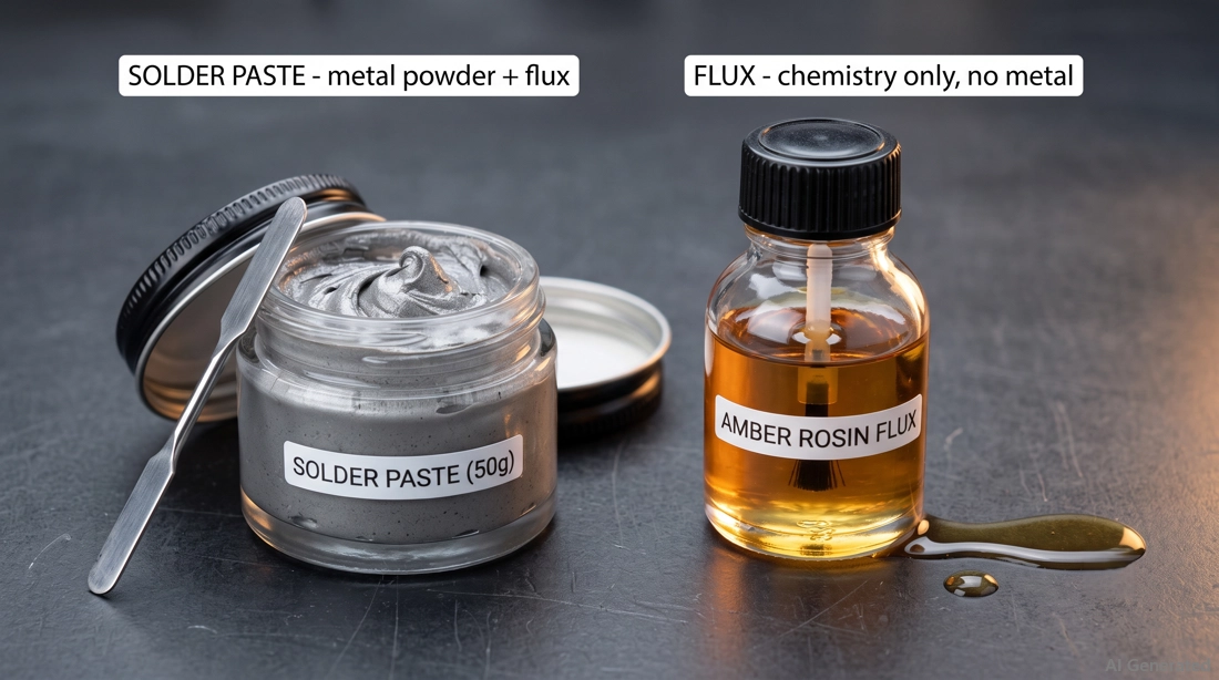
Figure: Solder paste and liquid flux
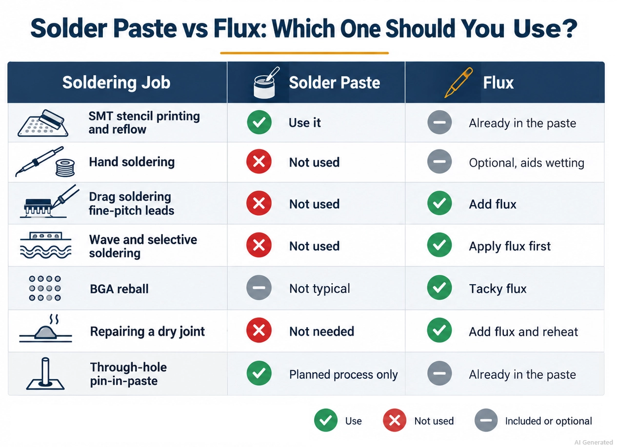
Solder Paste vs Flux: What's the Difference?
Solder paste combines solder alloy powder with flux, providing the metal needed to form a solder joint.
Soldering flux, by contrast, contains no solder alloy. Its primary role is to remove oxides and contaminants and prepare the metal surfaces for soldering.
In short, solder paste provides the solder, while flux prepares the surfaces for soldering.
| Property | Solder Paste | Solder Flux | Why It Matters |
|---|---|---|---|
| Composition | Solder powder in a flux vehicle | Rosin, resin, or organic acids in solvent | Only paste carries the joint metal |
| Physical form | Grey, thick, thixotropic paste | Amber liquid, gel, or tacky solid | Paste holds a shape, flux spreads |
| Deposits metal | Yes, typically 85 to 90% by weight | No, zero metal content | Flux alone cannot bridge the pad to lead |
| How it is applied | Stencil, syringe, or jet printing | Brush, pen, foam, or spray fluxer | Paste needs an aperture, flux needs coverage |
| Process it suits | SMT reflow assembly | Rework, wave, and selective soldering | Paste is a material, flux is a process aid |
| What decides cleaning | The flux fraction inside it | The flux chemistry itself | The alloy never sets the wash requirement |
| Typical storage | Refrigerated, 2 to 10 °C | Sealed at room temperature | Paste is perishable, so it needs rotation |
Can Flux Replace Solder Paste?
No. Flux activates and cleans the soldering surface, but it does not supply the solder alloy. If the process relies on solder paste to deposit the required solder volume, flux alone cannot replace it.
| Situation | Use |
|---|---|
| SMT stencil printing | Solder paste |
| Hand soldering with solder wire | Solder wire; additional flux if needed |
| Wave soldering | Flux + molten solder from the solder pot |
| BGA rework | Flux + solder balls, preforms, or solder paste, as required by the process |
| Repair / touch-up | Flux + additional solder if needed |
When You Need Standalone Flux Instead of Solder Paste
Use standalone flux when the required solder is already present or is supplied separately.
Solder paste contains both solder powder and flux, so adding it when another solder source is already provided can introduce excess solder and disrupt the intended process.
Common cases include:
- Hand rework and touch-up: Flux-cored solder wire already contains flux, but additional flux can improve wetting during difficult rework.
- Drag soldering fine-pitch parts: Additional flux improves wetting and helps solder flow across fine-pitch leads while reducing the risk of bridging.
- Wave and selective soldering: Flux is applied to the board or targeted areas, while the solder wave or solder pot supplies the molten solder.
- BGA reball: Tacky flux helps hold solder balls in position and promotes wetting during reflow.
- Wire and lead tinning: Flux removes or disrupts surface oxides and promotes solder wetting, allowing solder to flow more evenly onto wires and leads.
- Repairing a dry or poorly wetted joint: Applying flux and reheating the joint can improve wetting and reflow the existing solder without adding more solder.
The substitution does not work in reverse. Solder paste is not the solder-delivery medium in a conventional wave-soldering process; the solder is supplied by the molten solder wave.
Solder paste can be used for through-hole components in a planned pin-in-paste (intrusive reflow) process, where the stencil aperture and paste volume are designed to provide the required solder fill.
What Is Flux and How Does It Work?
Flux removes metal oxides, helps prevent re-oxidation during heating, and promotes the spreading and wetting of molten solder on the pad.
Without sufficient flux activity, oxides can prevent molten solder from properly wetting and bonding to the copper surface.
In short, flux removes or disrupts surface oxides, promotes solder wetting, and undergoes chemical and thermal changes during soldering.
- Oxide removal: Activators react with and disrupt metal oxides on the surface, allowing molten solder to contact the underlying metal.
- Oxidation barrier: The flux vehicle forms a protective layer that helps limit re-oxidation of the metal surface during heating.
- Wetting promotion: By removing surface oxides and improving the solder-metal interface, flux allows molten solder to spread more readily across the pad and component lead.
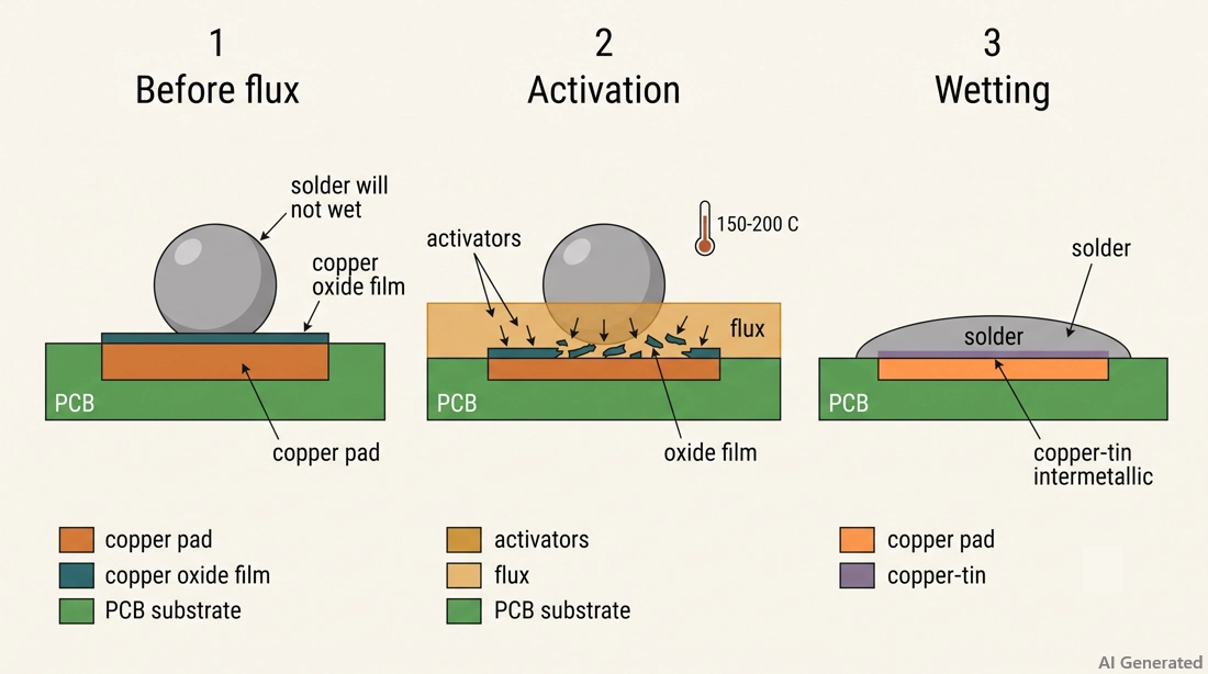
Figure: Three-stage copper pad cross-section showing oxide removal and solder wetting.
Why Oxides Prevent Solder Wetting
Bare copper starts oxidizing as soon as it comes into contact with air, and a thin oxide film forms within minutes.
Molten solder cannot properly wet and bond to an oxidized copper surface, so it beads up instead of wetting the copper. A reliable joint forms only when tin reaches clean copper and creates a copper-tin intermetallic layer.
The challenge is that oxidation increases rapidly as the board approaches reflow temperatures near 240 °C. Cleaning the pads before assembly is therefore not enough. Flux must remain active during heating, which is why its activation behavior at the operating temperature matters so much.
Flux Composition: Vehicles, Activators, and Solvents
Flux is made from a vehicle, activators, and solvents. The vehicle - usually rosin, resin, or an organic base protects the cleaned metal from re-oxidation. Activators, such as organic acids, amines, or halides, remove oxides during heating.
Their activation temperature matters: if they react too early, they may be exhausted before the solder melts. Solvents control viscosity and evaporate during preheat.
What Flux Cannot Do
Flux does not contain solder alloy, so it cannot fill gaps, build a solder fillet, or fix a starved joint. Adding more flux to a joint that lacks solder simply gives you a cleaner joint that still lacks solder.
Flux also cannot replace heat. Flux activity depends on the temperature range of the soldering process. If the surface does not reach the required activation range, the flux may not effectively remove oxides or promote wetting.
Heavily corroded surfaces are another limitation, because low-activity flux may be exhausted before it can remove severe oxidation or green corrosion.
What Is Solder Paste and What Is It Made Of?
Solder paste is a thixotropic mixture of spherical solder powder and flux, typically containing about 85–90% metal by weight. The high metal loading provides enough alloy to form the solder joints after reflow.
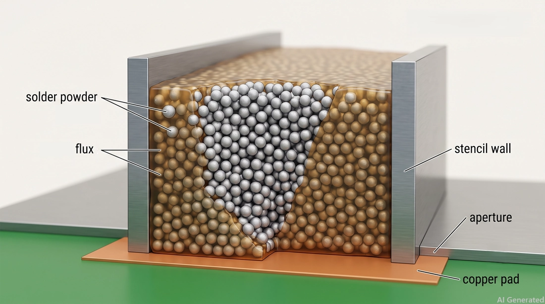
Figure: Spherical alloy particles suspended in the flux vehicle between stencil walls.
- Solder powder: Contains spherical alloy particles, graded by powder type.
- Flux vehicle: The rosin, resin, or organic base that protects the metal and carries the other flux components.
- Activators: Chemical compounds that react with or disrupt metal oxides on the pads, component terminations, and solder powder particles.
- Solvents and rheology modifiers: These components help control viscosity, tack, slump resistance, and printing behavior.
Rheology largely determines how solder paste behaves during stencil printing. A well-formulated paste should release cleanly from the stencil, maintain the printed deposit shape, and provide sufficient tack before reflow.
Why Solder Paste Already Contains Flux
The flux must remove oxides from the pad, component lead, and every solder particle before the powder can melt together. Even a small Type 4 deposit contains thousands of particles, each with its own oxide layer. That is why solder powder is mixed with flux rather than used dry.
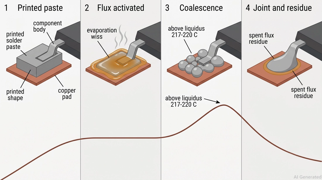
Figure: Reflow sequence showing printed paste, activated flux, coalescing solder particles, and the finished joint surrounded by flux residue.
- Preheat and soak: Solvents begin to evaporate, the paste's rheology changes, and flux activators become increasingly active.
- Oxide reduction: Activators clean the pads, the leads, and every particle inside the deposit.
- Coalescence: Once the alloy reaches its liquidus temperature, the solder particles melt and coalesce, while surface tension helps the molten solder form a continuous joint.
- Cooling and residue: The joint solidifies, and spent flux stays on the board as residue.
Note
Adding liquid flux to a printed solder paste deposit can sometimes cause printing and reflow problems.
Excess liquid can dilute the deposit or alter its rheology, increasing the risk of slump and solder bridging. Excess flux or solvent can also increase outgassing and spattering during reflow, potentially contributing to solder balling or other defects.
How to Choose Solder Paste
Solder paste selection comes down to two independent variables — alloy (melting behavior, reflow profile) and powder type (particle size, print resolution).
SAC305 vs Sn63Pb37
| SAC305 | Sn63Pb37 | |
|---|---|---|
| Composition | 96.5% Sn / 3.0% Ag / 0.5% Cu | 63% Sn / 37% Pb |
| Melting behavior | Non-eutectic; solidus/liquidus ~217/220 °C | Eutectic; melts at 183 °C |
| Typical peak reflow | ~235–250 °C, depending on paste and profile | Typically lower than lead-free profiles; follow the paste manufacturer's profile |
| Joint appearance | Duller or satin finish can be normal | Typically bright and shiny |
| Standard | IPC J-STD-006 | IPC J-STD-006 |
- Choose SAC305 for: lead-free commercial production where the process is designed around a SAC alloy and RoHS requirements apply.
- Choose Sn63Pb37 for: applications where tin-lead solder is specifically permitted or required, such as certain legacy designs, rework processes, or products covered by applicable exemptions.
Trade-off: SAC305 requires a higher reflow temperature than Sn63Pb37, increasing thermal exposure to components, PCB materials, and the flux system. Profile the process within the paste and component manufacturers' recommended limits.
Type 3 vs Type 4 vs Type 5
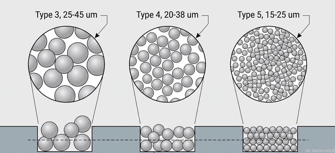
Figure: Solder powder Type 3, Type 4, and Type 5
| Powder Type | Nominal Particle Size | Practical Minimum Pitch | Typical Use |
|---|---|---|---|
| Type 3 | 25 to 45 µm | 0.65 mm (25.6 mil) and above | General SMT, larger-pitch components |
| Type 4 | 20 to 38 µm | 0.5 mm (19.7 mil) and finer | 0201, fine-pitch QFN, 0.5 mm BGA |
| Type 5 | 15 to 25 µm | Below 0.4 mm (15.7 mil) | 01005, micro-BGA, chip-scale packages |
Selection rule: match powder type to your smallest stencil apertures and printing requirements, not component pitch alone. Stencil thickness, aperture geometry, area ratio, paste formulation, and printing parameters also affect the achievable feature size. A common stencil-design guideline is to maintain an area ratio of at least 0.66 where practical.
Trade-off: finer powder can improve printing performance for small apertures and fine-pitch features, but its higher surface-area-to-volume ratio makes oxidation and handling more critical. Follow the solder paste manufacturer's storage, handling, and stencil-life requirements.
How to Choose the Right Solder Flux?
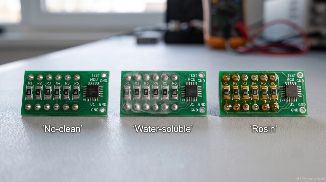
Figure: Comparison of test boards after reflow, showing no-clean, water-soluble, and rosin flux residue.
The decision comes down to one question: can the board be washed after reflow?
| No-Clean (ROL0/REL0) | Water-Soluble (ORH1) | Rosin/RMA | |
|---|---|---|---|
| Residue | Small, benign — stays on the board | Ionic — must wash within hours | Hard, tacky, visible |
| Wetting | Good | Strongest | Good |
| Cleaning required | No | Yes — hot DI water | Yes — solvent (mainly rework) |
| Typical use | No-wash production lines (commercial default) | High-reliability builds with a wash line | Hand soldering, rework |
- No-clean: Low-solids ROL0 or REL0 formulations leave a small amount of residue designed to remain on the board. They are well suited to SMT assembly without a dedicated wash line and are widely used in commercial production.
- Water-soluble: These fluxes use highly active organic-acid chemistries that generally provide strong wetting and oxide removal. Their ionic residues must be thoroughly removed after soldering according to the flux manufacturer's recommended cleaning process.
- Rosin (RMA): RMA fluxes leave rosin-based residues and are commonly used for hand soldering and rework, particularly when the residue will be removed afterward.
Residue appearance alone does not indicate whether a flux residue is safe to leave on a PCB. A visible no-clean residue can be electrically benign, while a less noticeable ionic residue can contribute to leakage or electrochemical migration under moisture and bias.
For high-reliability applications, ionic contamination and long-term reliability should be evaluated using appropriate cleanliness and reliability testing, including surface insulation resistance (SIR) testing where applicable.
Solder Paste and Flux in JLCPCB PCB Assembly
At JLCPCB, advanced SMT production lines and strict process control help ensure accurate solder paste deposition and controlled flux activity for consistent, high-quality solder joints. This helps reduce assembly defects and improve overall PCBA reliability.
JLCPCB supports fine-pitch SMT assembly with minimum IC pin pitches of 0.35 mm for Standard PCBA and 0.40 mm for Economic PCBA.
When selecting components, you can use the JLCPCB Parts Library to check available parts and their package information before finalizing your BOM and PCB footprint.
Conclusion
Solder paste and flux are not interchangeable: solder paste supplies the solder alloy, while flux prepares the surfaces for soldering.
Use solder paste when you need to deposit solder, and use standalone flux when solder is already present or supplied separately.
Choosing the right material for the process helps ensure proper wetting, reliable joints, and fewer soldering defects.
Once your design is ready, upload your files to JLCPCB to review assembly options and get an instant quote.
FAQs About Solder Paste vs Flux
Q: Is Solder Paste the Same as Flux?
No. Solder paste contains solder powder mixed with flux, while flux contains no solder metal. Paste forms the joint; flux mainly cleans oxides and improves wetting.
Q: Does Solder Paste Contain Flux?
Yes. Solder paste typically contains about 10–15% flux by weight. The flux helps remove oxides, allowing the solder to melt and properly wet the surfaces.
Q: Can I Use Flux Instead of Solder Paste?
Only when solder is supplied separately, such as with solder wire, wave soldering, or BGA balls. For stencil printing on bare pads, solder paste is required.
Q: Do I Need Extra Flux When Using Solder Paste?
Usually not. Solder paste already contains flux. Adding extra flux can cause slumping, bridging, solder balls, and excess residue.
Q: What Does ROL0 Mean on a Flux Label?
ROL0 means rosin-based, low-activity flux with less than 0.05% halide content by weight. It is commonly used in no-clean SMT assembly.
Popular Articles
• Logic Gate Symbols: The Complete Chart, Truth Tables [2026]
• How to Design and Assemble a Reliable ESP32 Module PCB on a 2-Layer Board
• How to Identify SMD LED Polarity: Markings, Testing, and PCB Tips
• The Ultimate Guide to Relay Symbol: Coil, Contacts, Diagrams, and Circuit Applications
• Power Supply Symbols Chart: A Complete Guide to AC, DC, Ground, Battery, and Source Symbols
Keep Learning
How to Read Resistor Color Code: Complete Guide with Chart and Examples
4-Band Resistor Color Code Explained A 4-band resistor color code is one of the most common methods used to indicate resistance values in electronic components. It is widely used to help engineers and hobbyists quickly determine resistance values without using a resistor color code calculator. In a standard 4-band resistor: First Band (Digit 1): Represents the first significant digit Second Band (Digit 2): Represents the second significant digit Third Band (Multiplier): Indicates the factor by which t......
Solder Paste vs Flux: What's the Difference and When Should You Use Each?
Solder paste and flux are not interchangeable. Solder paste contains solder alloy powder and flux, while flux contains no solder alloy. This difference matters when choosing materials for SMT, reflow soldering, or manual soldering. Flux removes metal oxides and prevents re-oxidation, allowing molten solder to wet copper pads and component leads properly. Solder paste combines flux with fine solder alloy powder. During reflow, the flux activates to improve wetting while the solder alloy melts to form t......
Fiducial Marks in PCB and SMT Assembly: A Complete Guide to Accuracy and Design Rules
Modern Printed Circuit Boards (PCBs) are complex, integrating high-density components like 0.4mm pitch Ball Grid Arrays (BGAs), 0201 passives, and fine-pitch Quad Flat No-Lead (QFN) packages. In this advanced manufacturing environment, achieving placement accuracy measured in micrometers is crucial. A significant challenge in automated manufacturing is how pick-and-place machines, which handle thousands of components per hour, precisely locate the PCB. A board on a conveyor system is never in the perf......
Ground Symbols Explained: Earth, Chassis, Signal, Analog, Digital Ground & More
Key Takeaways ⬇ Download the Ground Symbol Cheat Sheet (PDF) Keep all six ground symbols and their standard numbers on one page for quick reference. Four IEC 60417 symbols: IEC 60417 defines symbol 5017 for earth, 5018 for functional earth, 5019 for protective earth, and 5020 for frame/chassis. Protective earth is safety-related: IEC 60417-5019 identifies the protective earth connection and is used for safety-related protective bonding. Signal ground uses a different convention: IEEE Std 315 defines t......
How to Choose an ESP32 Development Board: A Beginner-Friendly Guide
The leap from blinking a simple LED to building a cloud-connected smart home device is a thrilling milestone for any electronics beginner. At the heart of this transition is often one undisputed champion: the ESP32. However, when you first search for an ESP32 development board, you are instantly met with a dizzying array of models, shapes, and specifications. How do you know which one is right for your first IoT (Internet of Things) project? In this beginner's guide, we will break down what makes thes......
How to Design an ESP32-S3 Development Board from Scratch: A 4-Layer PCB Design Tutorial
Designing your own ESP32-S3 development board gives you complete control over your hardware architecture while preparing your IoT projects for commercial production. Instead of relying on bulkier, off-the-shelf boards, building a custom design allows you to optimize the board space, expose only the required GPIO pins, and integrate peripherals directly onto a single substrate. In this tutorial, we will design a 4-layer ESP32-S3 development board from scratch. We will walk through the entire hardware d......