
Diode Symbol Guide: Meaning, Types & Circuit Diagram Examples
12 min
- Diode Symbols Image (Quick Reference)
- Types of Diode Symbols
- What Is a Diode Symbol?
- Diode Symbol Polarity: Anode vs Cathode Explained
- Diode Symbol in Circuit Diagram (Practical Examples)
- How to Read a Diode Symbol in a Schematic
- Diode Symbol vs Other Electronic Symbols
- Common Mistakes When Reading Diode Symbols
- Why the Diode Symbol Matters in PCB Design
- FAQs about Diode Symbol
- Conclusion
The diode symbol is the visual language engineers use to represent how a diode controls current flow in a circuit.
Think of a diode as a one-way street for your electronics. It acts like a valve that allows electrical current to flow freely in one direction. The schematic symbol is basically a visual map that perfectly illustrates this one-way traffic!
What you will learn in this guide:
- Identify anode and cathode (polarity)
- Understand forward vs reverse bias
- Learn common types of diode symbols
- See real circuit examples
- Read diode symbols step-by-step
- Move from schematic to PCB
Diode Symbols Image (Quick Reference)
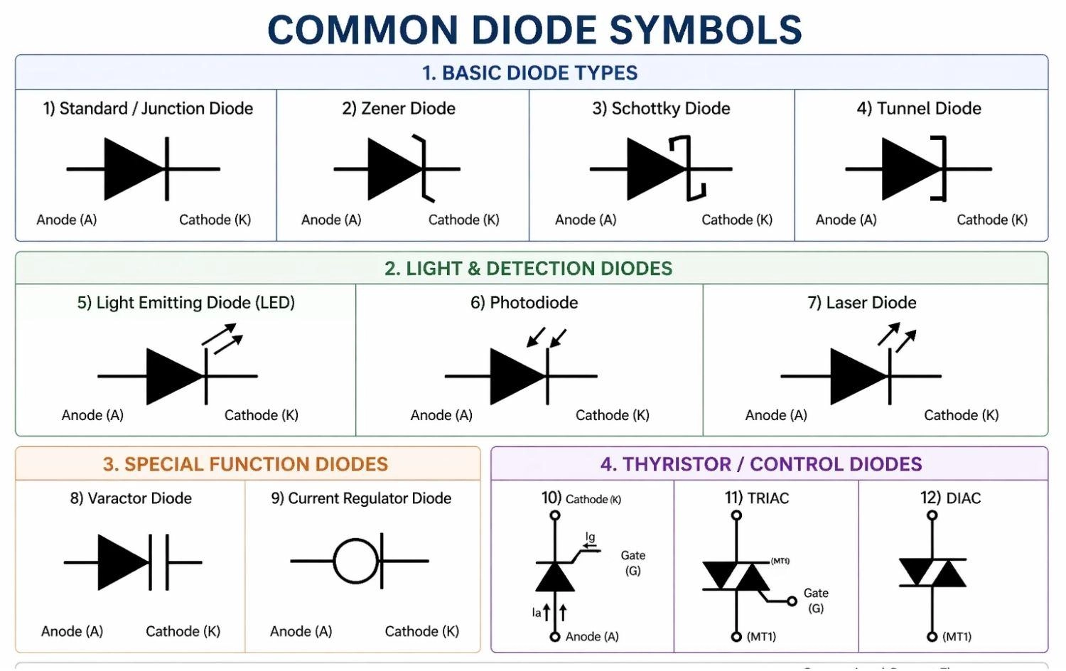
Figure: The schematic symbols for Standard (Junction), Zener, LED, Schottky, Photodiode, Tunnel, Varactor, Current Regulator, SCR, DIAC, and TRIAC Diodes.
Types of Diode Symbols
The most common diode symbols used in circuit diagrams include standard (PN junction), Zener, LED, Schottky, photodiodes, tunnel diodes, varactor diodes, SCRs, DIACs, and TRIACs.
Different applications require different types of diodes.
While they share the basic triangle-and-line structure, minor modifications to the cathode line denote specific functionalities.
Here’s a quick reference table:
| Diode Type | Symbol Description | Primary Function |
|---|---|---|
Standard (PN Junction / Rectifier) | Triangle pointing to a straight perpendicular line. | AC to DC conversion, basic signal routing, polarity protection. |
| Zener | Triangle pointing to a line with bent 'Z'-shaped edges. | Voltage regulation, safe reverse breakdown operation. |
| LED | Standard symbol with two arrows pointing away from it. | Emits light when forward-biased. |
| Schottky | Triangle pointing to a line with square, 'S'-shaped ends. | Fast switching, low forward voltage drop. |
| Photodiode | Standard symbol with two arrows pointing inward toward it. | Detects light, allows current flow based on light intensity. |
| Tunnel | Triangle pointing to a line with square, bracket-like extensions (']'). | High-frequency microwave applications, incredibly fast switching. |
| Varactor | Triangle pointing to a double line resembling a capacitor. | Voltage-controlled variable capacitance for tuning circuits. |
| Current Regulator | Standard diode symbol enclosed inside a circle. | Maintains a steady, constant current despite voltage changes. |
| SCR (Thyristor) | Standard symbol with an extra line (Gate) branching off. | Controlled one-way switching; conducts only when triggered. |
| DIAC | Two overlapping triangles facing opposite directions. | Bidirectional triggering; conducts both ways after a voltage threshold. |
| TRIAC | Two overlapping triangles with a third Gate terminal. | Controlled bidirectional (AC) switching; used in AC dimmers. |
1. Standard Diode Symbol (PN Junction / Rectifier Diode)
→ Used for rectification and basic signal routing
The standard symbol (very commonly referred to as a PN junction diode) features a basic straight line for the cathode. These are used for general-purpose applications like converting AC to DC power.
2. Zener Diode Symbol (Voltage Regulation)
→ Used for voltage regulation and safe reverse breakdown
The Zener diode symbol has bent edges on the cathode line, making it look slightly like the letter "Z". These diodes allow current to flow backward when a specific breakdown voltage is reached.
3. LED Symbol (Light Emitting Diode)
→ Emits light when forward-biased
The Light Emitting Diode (LED) symbol looks like a standard diode but includes two small arrows pointing away from the component to represent the emission of light.
4. Schottky Diode Symbol (Fast Switching)
→ Used for fast switching and low forward voltage drop
The Schottky diode features a cathode line with square, "S"-shaped bends at the ends, making them vital in high-frequency applications.
5. Photodiode Symbol (Light Detection)
→ Detects light and allows current flow based on intensity
The photodiode symbol is identical to the LED symbol, but the two small arrows point inward toward the diode, signifying light absorption.
6. Tunnel Diode Symbol (High-Frequency Oscillators)
→ Used for high-speed microwave applications and oscillators
The tunnel diode symbol features a cathode line with bracket-like extensions pointing in the same direction. Thanks to quantum tunneling, these diodes operate incredibly fast and are essential in microwave frequency circuits.
7. Varactor Diode Symbol (Variable Capacitance)
→ Used for voltage-controlled variable capacitance
The varactor diode (or varicap) symbol looks like a standard diode merged with a capacitor symbol at the cathode. It acts as a variable capacitor that adjusts based on reverse-bias voltage, making it crucial for tuning radios and TVs.
8. Current Regulator Diode Symbol (Constant Current)
→ Used to maintain a steady current flow
The current regulator diode (also known as a constant current diode) symbol usually looks like a standard diode enclosed in a circle. Unlike Zener diodes that regulate voltage, this diode's main job is to ensure the current remains at a specific, constant level, regardless of voltage fluctuations.
9. SCR Symbol (Silicon Controlled Rectifier)
→ Used for controlled high-power switching
The SCR (or thyristor) symbol looks like a standard diode but adds a third terminal called a gate. It acts as a controlled one-way valve—it completely blocks current until it receives a small electrical "push" at the gate terminal.
10. DIAC Symbol (Diode for Alternating Current)
→ Used for bidirectional triggering in AC circuits
The DIAC symbol looks like two triangles pointing at each other. Unlike standard diodes, it can conduct current in both directions, but only after a specific voltage threshold is reached. It’s mostly used to help trigger TRIACs.
11. TRIAC Symbol (Triode for Alternating Current)
→ Used for controlling alternating current (AC)
The TRIAC symbol combines the bidirectional shape of a DIAC with the gate terminal of an SCR. It acts as an electronic switch for AC, making it the perfect component for things like household light dimmers and motor speed controls.
In advanced circuits, Schottky diodes are preferred for high-speed switching due to their low forward voltage drop, while TRIACs rule the world of AC power manipulation.
What Is a Diode Symbol?
A diode symbol is a graphical representation used in circuit diagrams to show a component that allows current to flow in one direction.
The standard diode symbol consists of a triangle (anode) pressing against a straight perpendicular line (cathode). The triangle represents the direction of conventional current flow, while the line represents the barrier that prevents current from flowing backward.
Function of Diode Symbol in Circuit Diagrams
It shows how the diode should be oriented in a circuit.
Because diodes are polarized, incorrect placement can stop the circuit or cause damage. The symbol acts as an unambiguous map for current routing.
Where Diode Symbols Are Used (Schematics & PCB Design)
They are used in power supplies, signal circuits, and logic systems.
You’ll see them in both simple diagrams and advanced PCB design tools. Understanding how to read them is the first step toward moving a project from a digital schematic to physical hardware.
Diode Symbol Polarity: Anode vs Cathode Explained
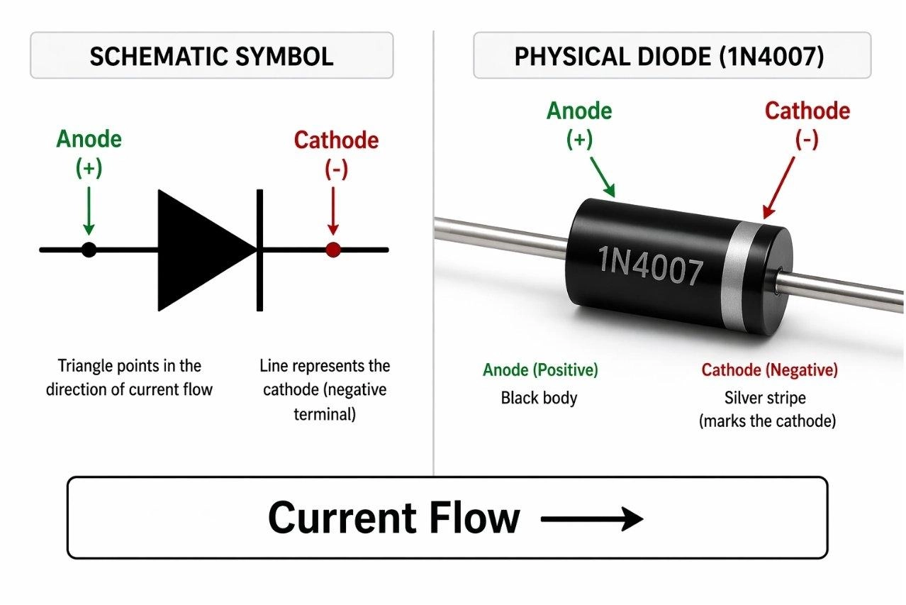
Figure: Comparing a standard diode schematic symbol to a physical through-hole diode, highlighting the anode (positive) and cathode (negative) terminals, with the physical cathode indicated by a silver stripe.
How to Identify the Anode and Cathode in a Diode Symbol
Understanding diode symbol polarity is everything when it comes to reading schematics correctly. On physical through-hole and SMD components, the cathode is usually indicated by a distinct stripe or notch.
- Anode: Triangle side
- Cathode: Line side
- Think: Triangle points toward the blocking line.
Current Flow Direction in a Diode Symbol
Conventional current flows from the positive side to the negative side. Therefore, current flows in the direction the triangle points—toward the line.
Forward vs Reverse Bias in Diode Symbols
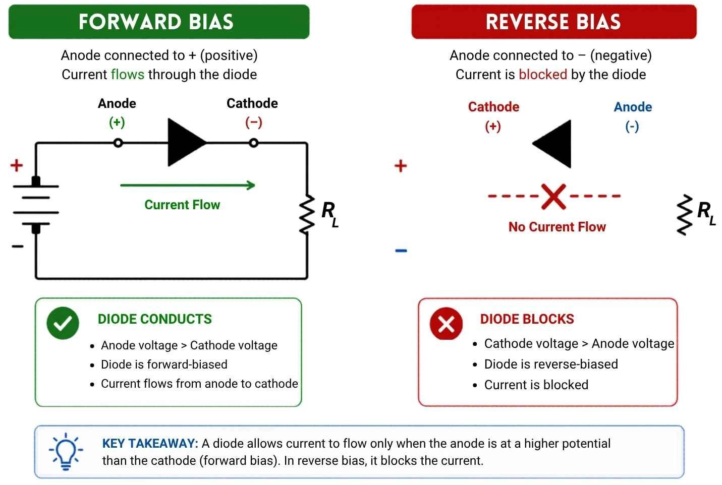
Figure: Diagram comparing forward bias, which allows current flow, against reverse bias, which blocks current in a diode.
Forward Bias
- Anode voltage > cathode
- Current flows
- Diode behaves like a closed switch
Reverse Bias
- Cathode voltage > anode
- Current blocked
- Diode behaves like an open switch
Learn more: SMD Diode Polarity Guide: Markings, Symbols, Tips
Diode Symbol in Circuit Diagram (Practical Examples)
These examples show how diode symbols are used in real circuits.
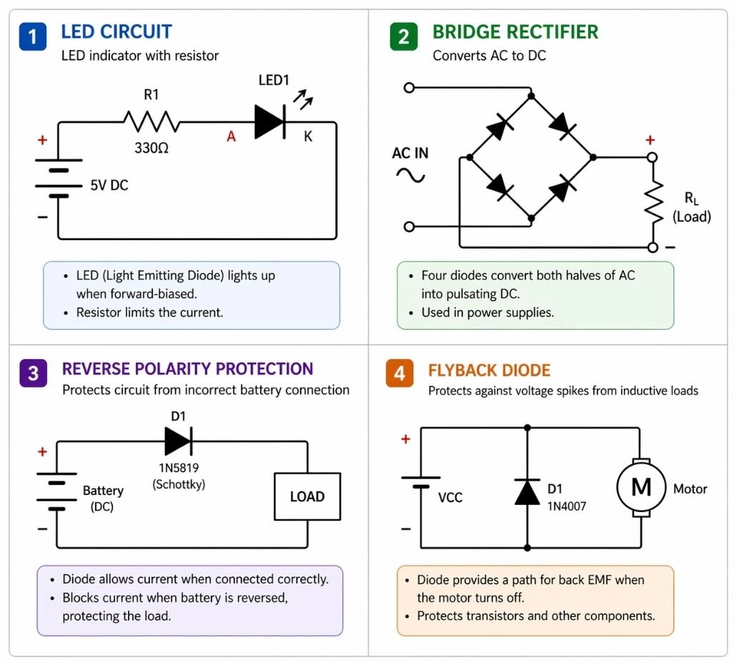
Figure: Four schematic diagram examples demonstrating practical uses of diodes: a basic LED circuit, a bridge rectifier for power supplies, a reverse polarity protection circuit, and a flyback diode across an inductive motor load.
LED Circuit Using Diode Symbol
- Lights up when current flows the correct way (forward-biased).
- Always needs a resistor to stop it from drawing too much power and burning out.
- Example: The tiny glowing power indicator on your TV or monitor.
Rectifier Circuit (AC to DC Conversion)
- Turns "wobbly" wall plug power (AC) into smooth, battery-style power (DC).
- Usually built using four diodes working together (called a bridge rectifier).
- Example: The charging brick for your smartphone or laptop.
Reverse Polarity Protection Circuit
- Saves your electronics from catching fire if you accidentally put a battery in backward!
- Acts as a strict one-way gate right where the power enters the board.
- Instantly blocks the reverse current, keeping sensitive chips safe.
Flyback Diode in Inductive Loads
- Protects the circuit from sudden electrical "zaps" or voltage spikes.
- These spikes happen naturally when turning off motors or magnetic relays.
- Installed pointing "backward" (reverse-biased) to safely catch and loop the energy spike until it fizzles out.
How to Read a Diode Symbol in a Schematic
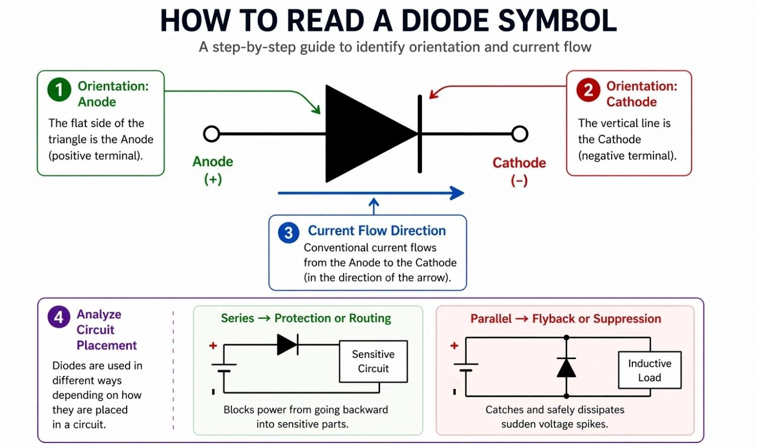
Figure: Step-by-step visual guide on how to read a diode symbol by identifying the orientation and current direction.
Step 1: Identify the Triangle and the Line
Locate the flat edge (anode) and the perpendicular line (cathode). This immediately tells you which side connects to the positive voltage and which connects to the negative.
Step 2: Check Diode Type and Labels
Look for designators like "D1" or "ZD" and note any special bends on the cathode line. Labels help you match the schematic symbol to the exact physical component on your parts list.
Step 3: Follow Current Flow Direction
Remember that current flows in the direction the triangle points. Trace the path from your battery or power supply to ensure it matches this natural flow for standard operation.
Step 4: Analyze Circuit Placement
- Series → protection or routing (blocks power from going backward into sensitive parts).
- Parallel → flyback or suppression (catches and safely dissipates sudden voltage spikes).
Diode Symbol vs Other Electronic Symbols
To read schematics fluently, it is important not to confuse the diode with other standard components.
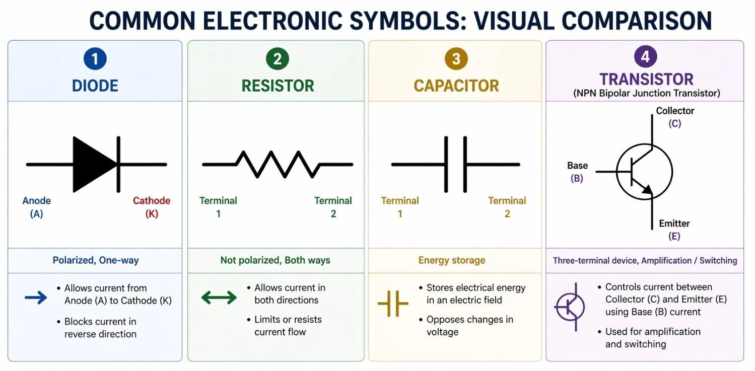
Figure: Showing the visual differences between the schematic symbols for a diode, resistor, capacitor, and transistor.
Diode vs Resistor Symbol
A resistor is represented by either a zig-zag line or a plain rectangle. You can learn more about reading them in this SMD resistor code guide.
- Not polarized
- Current flows both directions
Diode vs Capacitor Symbol
A capacitor symbol features two parallel lines. You can read our capacitor polarity guide to understand how their schematic symbols differ from diodes.
- Standard caps are unpolarized
- Electrolytic caps are polarized
Diode vs Transistor Symbol
Transistors involve a circle with lines branching off.
- Three terminals (Base, Collector, Emitter)
- Used for complex switching and amplification
Common Mistakes When Reading Diode Symbols
These are common beginner mistakes when reading diode symbols:
Reversing the Anode and the Cathode
→ Most common beginner mistake
Always remember: the schematic line equals the physical stripe. Installing it backward will stop your circuit from working.
Ignoring Polarity in Circuits
→ Can lead to dead circuits or damaged parts
Failing to recognize when a diode should intentionally be reverse-biased (like in the flyback example) can result in blown microcontrollers.
Misinterpreting LED vs Standard Diode
→ Causes manufacturing confusion
Using a standard diode symbol when you mean to use an LED can confuse other engineers or assemblers, leading to incorrect components being sourced.
Why the Diode Symbol Matters in PCB Design
Schematic to PCB Workflow for Diodes
Translating a diode from schematic to physical board requires a simple, step-by-step workflow:
- Symbol → Schematic: Place the symbol and map Pin 1 (Anode) and Pin 2 (Cathode).
- Schematic → Footprint: Pair the symbol with the correct physical layout constraint (surface mount vs through-hole).
- Footprint → PCB: Browse and assign the exact components you need directly from the JLCPCB Parts library.
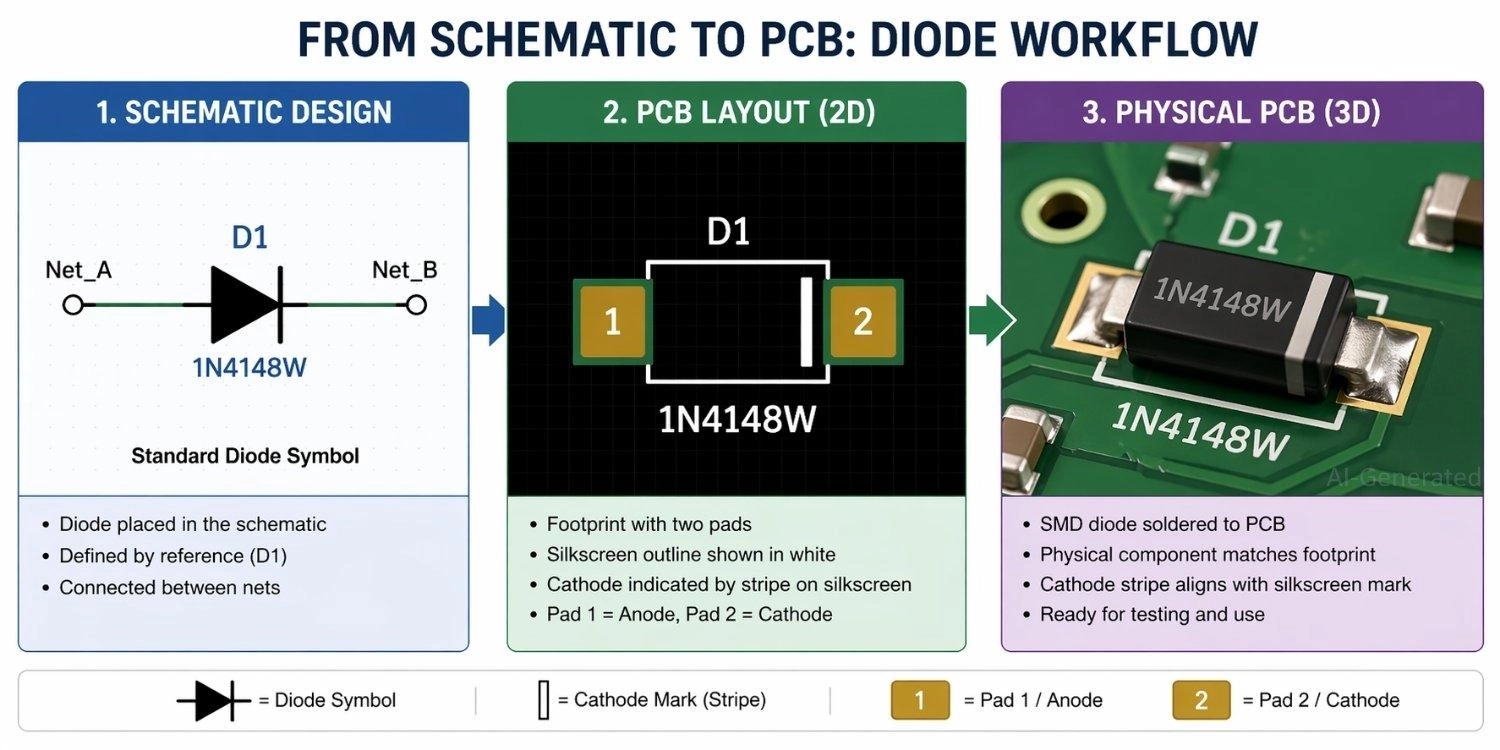
Figure: Showing a diode transitioning from a digital schematic symbol, to a PCB footprint, to a physical surface-mount component on a manufactured board.
PCB Manufacturing with JLCPCB
Translating a flawless schematic into a working board requires a reliable manufacturing partner. Whether you are building a simple prototype or scaling up, JLCPCB offers industry-leading fabrication.
By utilizing JLCPCB's PCB Assembly services, you can ensure that SMT machines perfectly align your diodes' polarity.
FAQs about Diode Symbol
Q: What is the arrow in a diode symbol?
It shows the current direction from the anode to the cathode.
Q: What does the line in a diode symbol represent?
It represents the cathode, acting as a visual "wall" that prevents current from flowing backward.
Q: Which side of a diode symbol is positive?
The flat side of the triangle (anode) is the positive side.
Q: Can current flow both ways in a diode?
No, standard diodes only allow current from anode to cathode. Zener diodes safely allow reverse flow at specific voltages.
Q: How do you identify the diode type from symbol?
Check the cathode line: straight (standard), "Z" shape (Zener), "S" bends (Schottky), or arrows (LED/Photodiode).
Q: What happens if a diode is reversed?
It blocks the current, acting as an open switch and stopping the circuit from working.
Conclusion
Understanding the diode symbol is a fundamental skill that helps you read schematics and design circuits correctly. By recognizing current direction, polarity, and the specific functions of different diode types, you can confidently work with real electronic systems—from simple DIY projects to complex industrial applications.
Whether you are adding a flyback diode to protect a motor or using a bridge rectifier for a power supply, getting the symbol right is your first step to success.
Popular Articles
• How to Create a Bluetooth-Controlled Car With Arduino: A Step-by-Step Guide
• How to Design and Assemble a Reliable ESP32 Module PCB on a 2-Layer Board
• The Ultimate Guide to Relay Symbol: Coil, Contacts, Diagrams, and Circuit Applications
• How to Identify SMD LED Polarity: Markings, Testing, and PCB Tips
• The Ultimate Guide to PCBA: Process,Types and Techniques for the Electronics Enthusiast
Keep Learning
How to Design an ESP32-S3 Development Board from Scratch: A 4-Layer PCB Design Tutorial
Designing your own ESP32-S3 development board gives you complete control over your hardware architecture while preparing your IoT projects for commercial production. Instead of relying on bulkier, off-the-shelf boards, building a custom design allows you to optimize the board space, expose only the required GPIO pins, and integrate peripherals directly onto a single substrate. In this tutorial, we will design a 4-layer ESP32-S3 development board from scratch. We will walk through the entire hardware d......
Arduino LED Driver Tutorial: Control More LEDs with 74HC595 and MAX7219
Arduino GPIO pins run out quickly in larger LED projects. By utilizing dedicated LED drivers and expansion ICs, you can drastically reduce pin usage, eliminate processor-heavy multiplexing loops, and simplify display wiring. In this guide, you will learn the operational architecture, wiring configurations, cascading techniques, and optimization strategies for the 74HC595 shift register and the MAX7219 LED driver. Why Arduino Projects Need LED Driver ICs Arduino GPIO and Current Limitations An ATmega32......
How to Create a Bluetooth-Controlled Car With Arduino: A Step-by-Step Guide
This tutorial walks through the complete engineering and implementation of a two-wheel Bluetooth RC car with an Arduino Nano module on a specially designed PCBA (Printed Circuit Board Assembly). While many hobbyists start by wiring motors and Bluetooth modules with jumper cables on a breadboard, this approach is prone to disconnection and signal noise. This guide upgrades that process by teaching you how to design a professional mainboard. Key Design Features Controller: Arduino Nano used as a plug-in......
Fiducial Marks in PCB and SMT Assembly: A Complete Guide to Accuracy and Design Rules
Modern Printed Circuit Boards (PCBs) are complex, integrating high-density components like 0.4mm pitch Ball Grid Arrays (BGAs), 0201 passives, and fine-pitch Quad Flat No-Lead (QFN) packages. In this advanced manufacturing environment, achieving placement accuracy measured in micrometers is crucial. A significant challenge in automated manufacturing is how pick-and-place machines, which handle thousands of components per hour, precisely locate the PCB. A board on a conveyor system is never in the perf......
Alternating Current vs Direct Current (AC vs DC): What's the Difference?
Electric current flows in two primary forms: alternating current (AC) and direct current (DC). AC periodically reverses direction, while DC flows steadily in one direction. AC powers the industrial and residential electrical grids, while DC powers batteries, electric vehicles, and nearly all modern consumer electronics. Understanding the core differences between AC and DC matters when designing power supplies, selecting electronic components, or laying out printed circuit boards (PCBs). This guide com......
Arduino LED Multiplexing Tutorial: Control More LEDs with Fewer Pins
The Arduino Uno is a powerful tool for prototyping, but driving multiple LEDs directly quickly exhausts its 20 GPIO pins and its 200 mA absolute maximum package current limit. To bypass these hardware bottlenecks, engineers and hobbyists use LED multiplexing to scale display outputs efficiently without upgrading the microcontroller. In this guide, you will learn the core principles of LED matrix scanning, Charlieplexing, refresh timing, ghosting fixes, and practical Arduino code without relying on any......