Power Supply Symbols Chart: A Complete Guide to AC, DC, Ground, Battery, and Source Symbols
20 min
- Power Supply Symbols Chart (Quick Reference)
- What Is a Power Supply Symbol?
- DC Power Supply Symbol
- AC Power Supply Symbol
- Battery Symbols: Single-Cell vs Multi-Cell
- Ground Symbols: Earth, Chassis, and Signal Ground
- Constant Voltage Source vs Constant Current Source Symbols
- Dependent (Controlled) Source Symbols
- Power Rail Labels: VCC, VDD, VSS, VEE, and GND
- Power Supply Symbols: IEC 60617 vs ANSI/IEEE 315
- How to Read Power Supply Symbols in a Circuit
- Common Power Supply Symbol Mistakes
- From Power Supply Symbol to PCB Footprint
- Conclusion
- FAQs About Power Supply Symbols
Note
⬇ Download the Power Supply Symbols Cheat Sheet [PDF]
Keep the most common power supply symbols, standards, and meanings at hand. Get the free PDF for quick reference while designing or reviewing schematics.
Power supplies are one of the most fundamental parts of electronic circuits. When reading a schematic, you may encounter different power-related symbols, including AC sources, voltage supplies, and ground references.
Although some symbols look simple, each one represents a specific electrical function. Misunderstanding these symbols can lead to incorrect connections, unexpected circuit behavior, or even EMC issues in PCB designs.
In this guide, you will learn:
- The full power supply symbol chart, from DC and AC sources to batteries
- How earth, chassis, and signal ground symbols differ
- Why do dependent sources use a diamond instead of a circle
- Where IEC and ANSI symbol conventions disagree
- How each symbol maps to a real PCB footprint
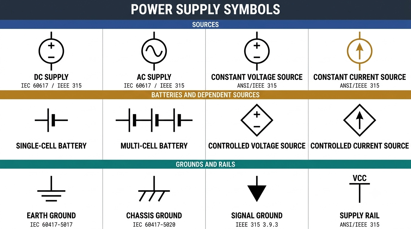
Figure: A complete power supply symbol chart
Key Takeaways
- Circle means independent: A plain circle carries a source that does not depend on anything else in the circuit.
- Diamond means dependent: The diamond outline is the only thing marking a controlled source on a schematic.
- Long bar is positive: In the standard battery symbol, the longer line represents the positive terminal, while the shorter line represents the negative terminal.
- Ground symbols are not interchangeable: earth, chassis, and signal ground are three separate nets.
- Net names define connectivity: In EDA tools, electrical connections are determined by net names and symbol pin assignments, not only by the visual appearance of schematic symbols.
Power Supply Symbols Chart (Quick Reference)
Fourteen symbols cover almost every power source you will meet on a schematic. They split into four families: sources, batteries, grounds, and rail labels.
| Symbol Shape | Name | What It Represents | Standard Reference |
|---|---|---|---|
| Circle with + and - terminals | DC voltage supply | A fixed DC potential difference | IEC 60617, ANSI/IEEE 315 |
| Circle with a sine wave inside | AC supply | A sinusoidal voltage source | IEC 60617, ANSI/IEEE 315 |
| Circle with an arrow inside | Constant current source | A fixed current, whatever the load voltage | ANSI/IEEE 315 |
| Circle with + and - inside | Constant voltage source | A fixed voltage, whatever the load current | ANSI/IEEE 315 |
| One long bar, one short bar | Single-cell battery | A single electrochemical cell | ANSI/IEEE 315 |
| Repeated long and short bar pairs | Multi-cell battery | Two or more cells in series | ANSI/IEEE 315 |
| Diamond with + and - inside | Controlled voltage source | Voltage set by another circuit quantity | Drafting convention |
| Diamond with an arrow inside | Controlled current source | Current set by another circuit quantity | Drafting convention |
| Three horizontal bars, each shorter | Earth ground | A connection to earth | IEC 60417-5017, IEEE 315 clause 3.9.1 |
| One bar with three angled strokes | Chassis ground | A connection to the frame or enclosure | IEC 60417-5020, IEEE 315 clause 3.9.2 |
| Downward-pointing triangle | Signal ground (common) | The circuit's own 0 V return | IEEE 315 clause 3.9.3 |
| Stem with an upward bar or arrow | Supply rail (VCC, VDD) | A named positive supply net | EDA library convention |
| Solid line above a dashed line | DC mark (equipment) | Direct current, on a label or panel | IEC 60417-5031 |
| Single sine wave | AC mark (equipment) | Alternating current, on a label or panel | IEC 60417-5032 |
Note
The last two rows are equipment markings, not schematic symbols. IEC 60417 defines graphical symbols used on equipment, such as product labels, controls, and indicators. IEC 60617 defines graphical symbols used in electrical diagrams and schematics. Mixing these two symbol sets is a common mistake in published symbol charts.
What Is a Power Supply Symbol?
A power supply symbol is a standardized graphical symbol used in schematics to represent a power source, supply rail, or reference connection.
Instead of using lengthy written descriptions, these symbols allow engineers to identify electrical functions quickly and consistently.
Depending on the symbol type, power-related symbols can communicate several types of information:
- Source type: Whether the circuit uses a DC source, AC source, battery, or dependent source.
- Polarity/direction: What is the positive terminal or the direction of conventional current flow?
- Reference role: If the node is a supply, return or safety connection.
The symbol itself does not define current rating, regulation performance, or physical specifications. Those live in the reference designator, the value field, and the bill of materials.
DC Power Supply Symbol
The DC power supply symbol is a circle containing a plus sign at one terminal and a minus sign at the other. It represents a source that holds one terminal at a higher potential than the other, with no reversal over time.
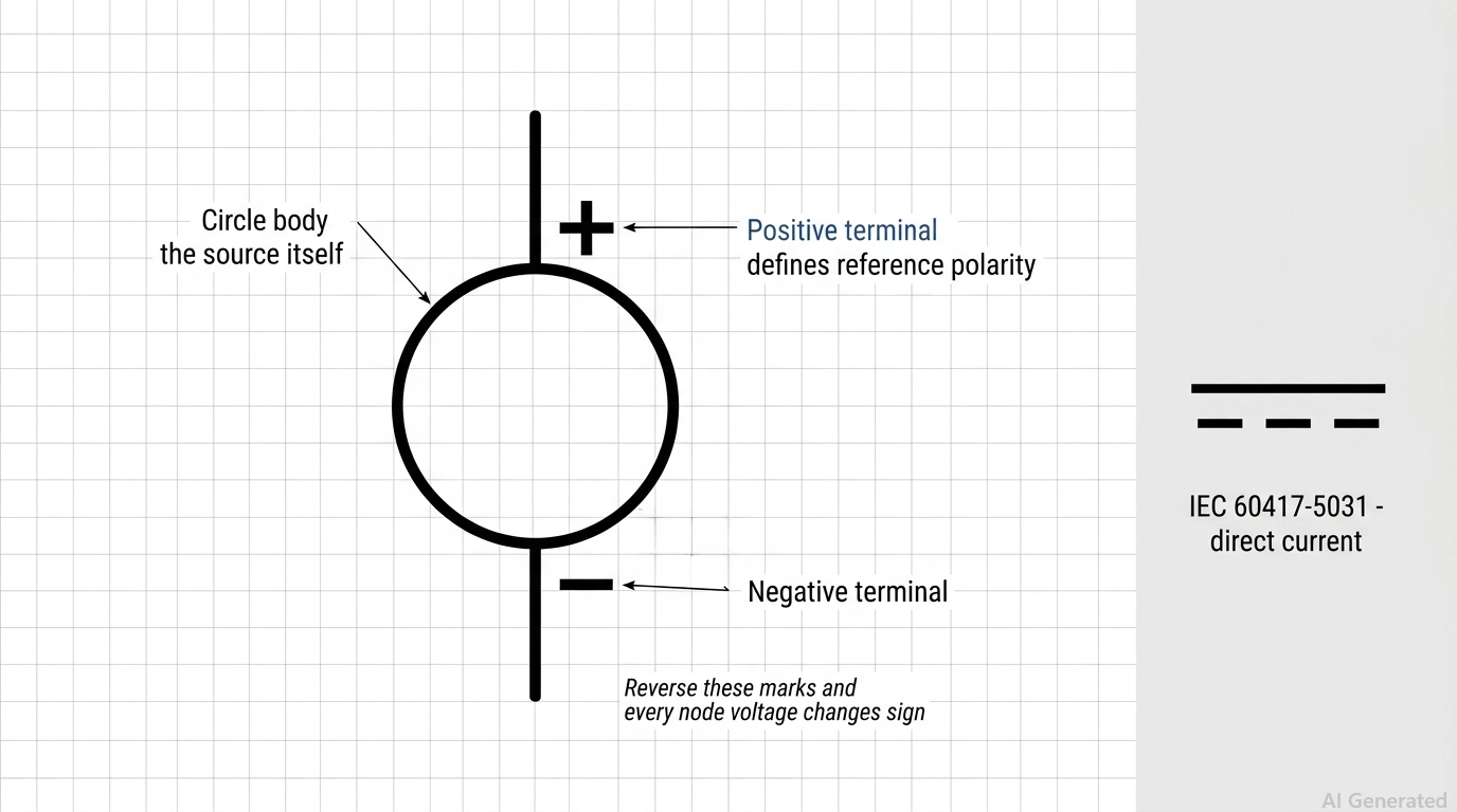
Figure: The DC power supply symbol marked positive and negative terminals.
Circle With Plus and Minus Terminals
The circle is the source body. The plus and minus marks sit inside or immediately beside the terminals, and they define the reference polarity for every calculation on the sheet. Reverse the marks and every node voltage derived from that source changes sign.
The Line-and-Dash DC Mark
On equipment labels, panels, and power bricks, you meet a different glyph: a solid horizontal line above a dashed line, defined as IEC 60417-5031. It means direct current. It is a marking, not a schematic symbol, so it belongs on a silkscreen or a rating plate rather than in a netlist.
DC Voltage Source vs DC Current Source
Both are circles, and the contents tell them apart. Plus and minus marks make it a voltage source. A single arrow through the body makes it a current source, and that arrow points in the direction of conventional current.
AC Power Supply Symbol
The AC power supply symbol is typically drawn as a circle containing a sine wave. It represents an alternating voltage source where polarity changes periodically over time. Unlike a DC source, neither terminal remains permanently positive or negative, so fixed + and − polarity markings are not used.
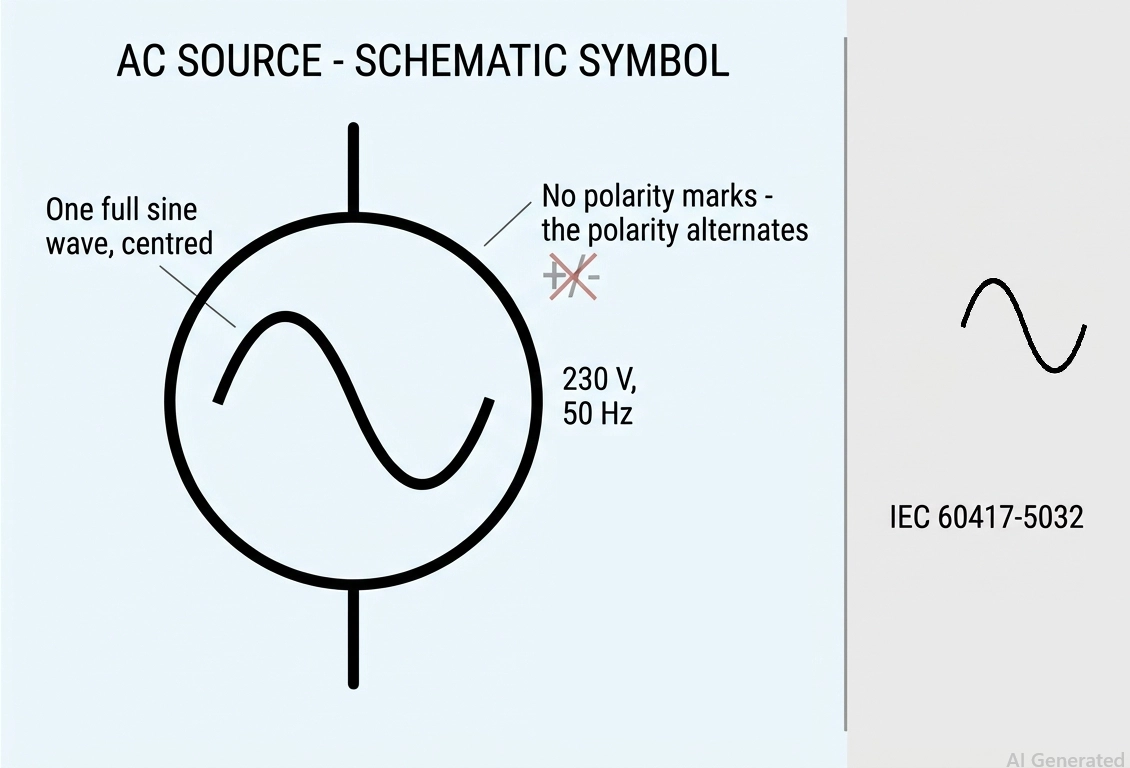
Figure: AC power supply represented by a circle with a single sine wave.
Single-Phase AC Source Symbol
A single-phase AC source symbol consists of a circle containing a sine wave with two connection terminals.
AC sources are indicated by values next to them as RMS voltage and frequency, such as 230 V and 50 Hz. The symbol does not indicate the amplitude of the signal; an unlabeled AC source is an incomplete diagram.
Symbols for Three-Phase and Mains Inlet
Three-phase supplies are modeled as three independent single-phase supplies with the phase designation, in wye or delta configuration.
An AC mains input is usually shown as a connector or terminal entry point rather than a standalone AC source symbol. Practical circuits often include protection components such as fuses, filters, and surge protection near the mains input.
Upstream of a rectifier from an AC source is the first place where your board becomes a high-voltage design and requires creepage and clearance rules. Consider all input-side components as a critical section.
Battery Symbols: Single-Cell vs Multi-Cell
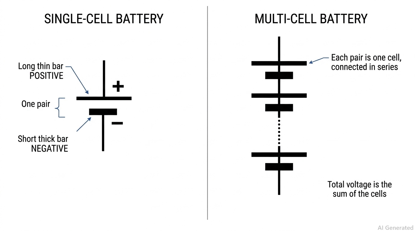
Figure: Single-cell and multi-cell battery symbols
A battery symbol is a pair of parallel bars of unequal length, and the rule never changes: the long thin bar is the positive terminal, the short thick bar is negative. One pair is one cell. Repeated pairs are cells in series.
| Property | Single-Cell Battery | Multi-Cell Battery |
|---|---|---|
| Symbol | One long bar and one short bar | Two or more long and short pairs in line |
| Meaning | One electrochemical cell | Cells connected in series |
| Typical voltage | 1.2 V to 3.7 V, depending on chemistry | The sum of the individual cell voltages |
| Common shorthand | Drawn as-is | A dotted break between pairs for a long stack |
| Typical use | Coin cell, single AA, single Li-ion | Battery pack, 9 V block, series stack |
A long series stack is rarely drawn cell by cell. Most schematics show two pairs, a dotted break, then a final pair, with the total voltage written alongside. That shorthand keeps the sheet readable without hiding the series connection.
Note: The bar lengths carry the polarity, not the order in which you drew them. If your library symbol has equal-length bars, fix the library. An equal-bar battery is ambiguous, and an engineer reviewing your schematic will flag it.
Ground Symbols: Earth, Chassis, and Signal Ground
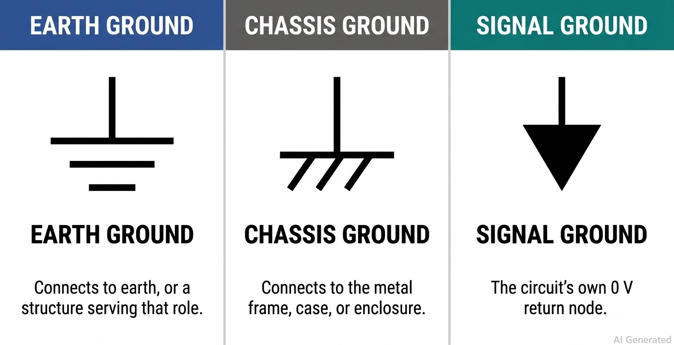
Figure: Earth, chassis, and signal ground symbols
Ground symbols identify a circuit's reference potential or a connection to earth, chassis, or another designated ground network. They may also provide a return path, depending on the circuit and grounding scheme.
These ground symbols represent different functions and should not be treated as interchangeable.
| Symbol | Construction | Function | When To Use |
|---|---|---|---|
| Earth ground | Vertical stem to three horizontal bars, each shorter than the one above | Connection to earth or to a structure serving that role | Mains-powered equipment, protective earth, lightning return |
| Chassis ground | Vertical stem to one bar with three short angled strokes beneath | Connection to the metal frame, case, or enclosure | Shielding cans, racks, automotive body return, airframe |
| Signal ground | Short stem meeting the flat top of a downward triangle | The circuit's own 0 V reference node | Every low-voltage analog and digital return path |
Chassis Ground Is Not Earth Ground
The distinction matters because a chassis is not automatically at earth potential. IEEE 315 clause 3.9.2 notes explicitly that a chassis or frame may sit at a substantial potential relative to the earth around it. If you want them bonded, draw the bond as a deliberate connection with its own designator.
AGND, DGND, and PGND Named Returns
Named variants such as AGND, DGND, and PGND all reuse the signal ground triangle. The shape stays identical and only the label inside changes, which is what allows a layout tool to keep three separate returns and join them at one defined tie point.
Constant Voltage Source vs Constant Current Source Symbols
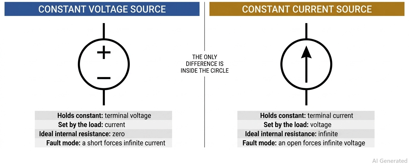
Figure: Constant voltage source symbol vs constant current source symbol
Both symbols are typically drawn as circles, but their internal markings distinguish the two source types.
A constant voltage source maintains a specified terminal voltage while the load determines the resulting current. A constant current source maintains a specified current while the load determines the resulting terminal voltage.
| Property | Constant Voltage Source | Constant Current Source |
|---|---|---|
| Symbol contents | Plus and minus polarity marks | An arrow along the terminal axis |
| Held constant | Terminal voltage | Terminal current |
| Set by the load | Current | Voltage |
| Ideal internal resistance | Zero | Infinite |
| Fault behaviour | Short circuit → theoretically infinite current | Open circuit → theoretically infinite voltage |
| Real example | Bench supply in CV mode; regulated power supply or LDO within its operating range | Constant-current LED driver; current mirror; bench supply in CC mode |
Why Ideal Source Symbols Differ from Real Hardware
Ideal sources do not exist because a real supply has finite internal resistance, so it behaves as a voltage source until the current demand becomes large enough that the internal drop dominates. That crossover is exactly what a bench supply is showing you when it switches from CV to CC.
The arrow direction on a current source is not decoration. It defines the reference direction for the current, and a solution that returns a negative value simply means that the real current flows in the opposite direction.
Dependent (Controlled) Source Symbols
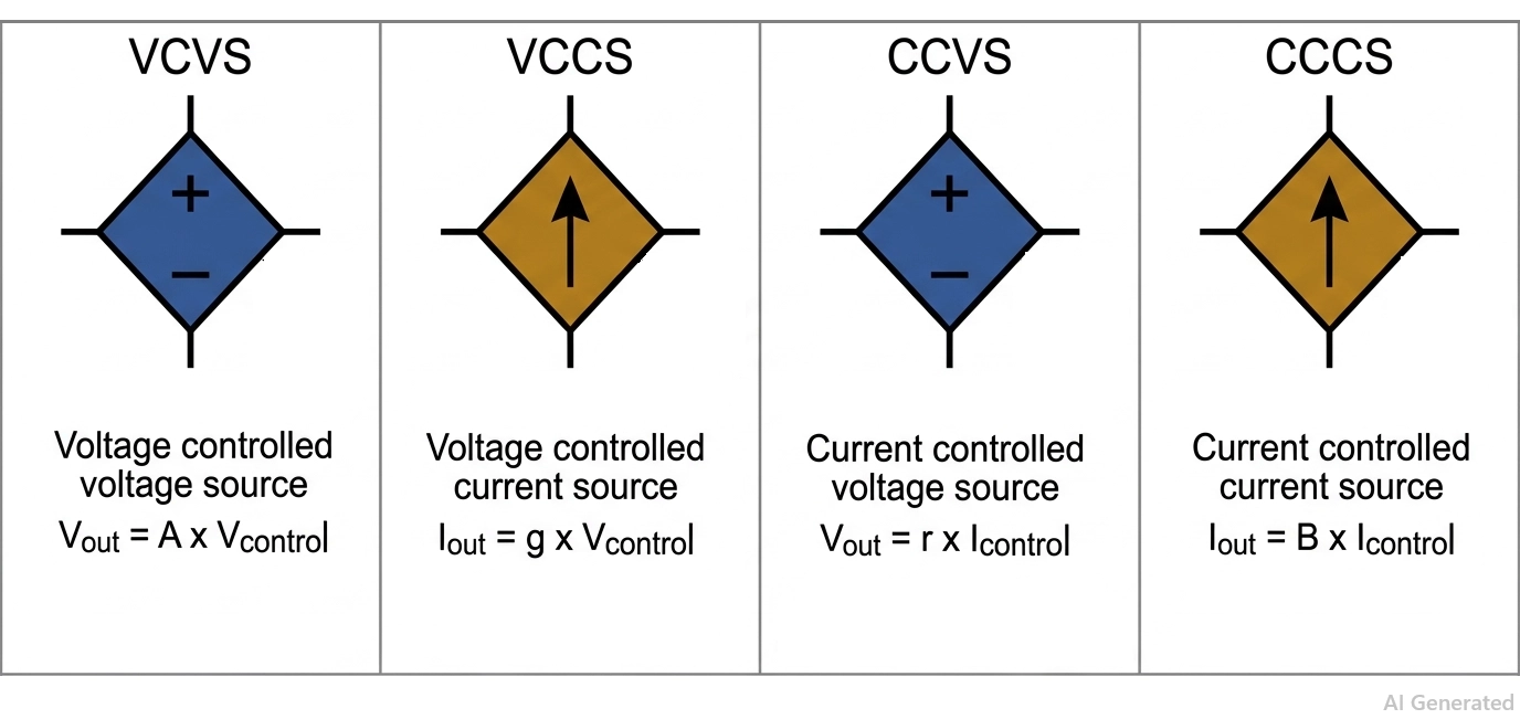
Figure: The four dependent source symbols
A dependent source, also called a controlled source, produces an output that is controlled by a voltage or current elsewhere in the circuit.
It is typically drawn as a diamond rather than a circle. The diamond distinguishes a dependent source from an independent source, while the internal markings indicate whether it is a voltage or current source.
The Four Dependent Source Types
| Type | Abbreviation | Symbol Contents | Output Equation | Gain Parameter |
|---|---|---|---|---|
| Voltage-controlled voltage source | VCVS | Diamond with plus and minus marks | Vout = A x Vcontrol | Dimensionless voltage gain |
| Voltage-controlled current source | VCCS | Diamond with an arrow | Iout = g x Vcontrol | Transconductance, in siemens |
| Current-controlled voltage source | CCVS | Diamond with plus and minus marks | Vout = r x Icontrol | Transresistance, in ohms |
| Current-controlled current source | CCCS | Diamond with an arrow | Iout = B x Icontrol | Dimensionless current gain |
The controlling quantity is always named on the schematic, usually as a labeled branch current or a labeled node voltage elsewhere on the sheet. Without that label, the symbol is unusable, because nothing tells you what the output follows.
Where Dependent Source Symbols Appear in Real Circuits
Dependent sources are not a textbook abstraction. They are how every active device is modeled:
- A bipolar transistor in its small-signal model is a CCCS, with collector current following base current.
- A MOSFET is a VCCS, with drain current following gate-source voltage.
- An ideal op-amp is a VCVS, with the output following the differential input.
- A transimpedance amplifier can be modeled as a CCVS, converting an input current into an output voltage.
Unlike the earth mark, which is numbered in IEC 60417, the diamond is not a numbered entry in IEC 60617, but it is almost universally used as a drafting convention.
It's been used throughout circuit theory books, in SPICE and later circuit simulators, and in EDA libraries, so use it as the de facto standard of practice, but don't quote a clause number for it that does not exist.
For the op-amp case, our op-amp symbol guide covers how the supply pins are drawn and why they are often hidden.
Power Rail Labels: VCC, VDD, VSS, VEE, and GND
Rail labels are power supply symbols in text form. A short stem with an upward bar or arrow, carrying a name, declares a supply net without drawing a wire all the way back to the source.
| Label | Meaning | Origin | Typical Use |
|---|---|---|---|
| VCC | Positive supply, collector | Bipolar transistor collector terminal | Legacy TTL and bipolar logic are still used generically |
| VDD | Positive supply, drain | MOSFET drain terminal | CMOS logic, microcontrollers, most modern digital ICs |
| VSS | Negative supply or 0 V, source | MOSFET source terminal | CMOS ground return |
| VEE | Negative supply, emitter | Bipolar transistor emitter terminal | Negative rail on op-amps and analog parts |
| GND | Circuit common, 0 V | Generic | The return node in almost every low-voltage design |
VCC vs VDD: Which Label Should You Use?
In modern practice, VCC and VDD are used interchangeably for the positive rail, and VSS and GND are used interchangeably for the return. The distinction survives from device physics rather than from any current standard.
Historically, when transistors (BJT) are used, the supplies have to power the collector, hence named VCC. Now CMOS is everywhere. The drain is powered by the supplies; hence, VDD is named.
In modern practice, while label selection often reflects design conventions, the best practice is always to follow the power-pin names in the component datasheet.
Note
Rail labels connect by name. Two symbols labeled VDD are the same net, even if they sit on different sheets and are never joined by a visible wire. That is a feature when you use it deliberately and a hard-to-find bug when you typo a name.
Power Supply Symbols: IEC 60617 vs ANSI/IEEE 315
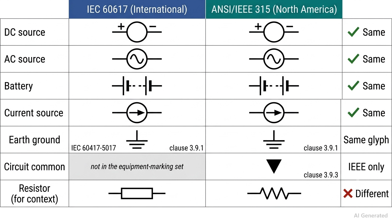
Figure: IEC 60617 and ANSI/IEEE 315 electrical symbol comparison
IEC 60617 governs graphical symbols for diagrams internationally, and ANSI/IEEE 315 is the North American equivalent.
| Symbol | IEC 60617 Practice | ANSI/IEEE 315 Practice | Agreement |
|---|---|---|---|
| DC source | Circle with polarity marks | Circle with polarity marks | Same |
| AC source | Circle with a sine wave | Circle with a sine wave | Same |
| Battery | Long and short bar pairs | Long and short bar pairs | Same |
| Current source | Circle with a direction arrow | Circle with a direction arrow | Same |
| Earth ground | Three shrinking bars | Three shrinking bars, clause 3.9.1 | Same glyph, different reference |
| Chassis ground | Single bar with angled strokes | Single bar with angled strokes, clause 3.9.2 | Same glyph, different reference |
| Circuit common | Not in the equipment-marking set | Downward triangle, clause 3.9.3 | IEEE names it explicitly |
| Resistor (for context) | Plain rectangle | Zigzag line | Genuinely different |
The resistor row is included because it is where engineers first notice the two standards diverge. For power sources specifically, however, a schematic drawn to either standard remains fully understandable to engineers trained in the other.
How to Read Power Supply Symbols in a Circuit
Read power symbols in a fixed order, and a schematic resolves quickly. Work from the source down to the return, then check the references.
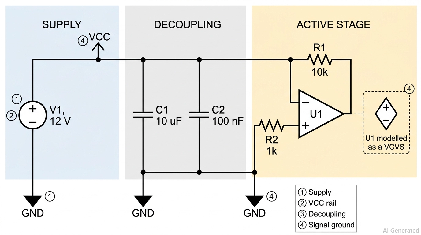
Figure: A worked example schematic showing a supply rail, decoupling, a dependent source, and the ground return path.
- Find the source and identify its family. Circle for independent, diamond for dependent, bar pairs for a battery. The outline answers this before you read any label.
- Read the contents for type and direction. Polarity marks mean a voltage source, an arrow means a current source, and a sine wave means AC.
- Trace the positive rail across the sheet. Collect every rail label that matches, since they are the same net whether or not a wire joins them.
- Identify every ground glyph separately. Count how many distinct return symbols appear. Two different symbols mean two different nets.
- Locate the tie point. Find where the separate returns meet, usually a single net tie or zero-ohm link. If you cannot find one, the schematic has a defect.
- Check the controlling variable on any diamond. A dependent source without a named control is incomplete.
Common Power Supply Symbol Mistakes
Most power symbol errors are drafting errors that survive review because the schematic still looks plausible.
- Drawing a dependent source as a circle: this is the single most common error, and it makes a controlled source read as an independent supply. Simulation then converges on a completely wrong operating point.
- Tying chassis ground to earth ground implicitly: placing both symbols on the same net without an explicit bond creates a ground loop that shows up as a failed EMC scan, not as a DRC error.
- Equal-length battery bars: the polarity becomes ambiguous, and a reversed cell holder on the board follows.
- Unlabelled AC sources: an AC symbol without RMS voltage and frequency cannot be built or simulated.
- Using IEC 60417 equipment marks on a schematic: the line-and-dash DC mark belongs on a rating plate, not in a netlist.
- Reusing GND for analog and power returns: one net name collapses two returns that needed separating, and the switching noise ends up in your reference.
From Power Supply Symbol to PCB Footprint
A power symbol only becomes a physical connection when it acquires a footprint, a net class, and copper. This is the step where schematic decisions turn into manufacturable ones.

Figure: A workflow strip tracing one power supply symbol
| Schematic Element | Becomes On The Board | The Design Decision It Forces |
|---|---|---|
| DC source symbol | Barrel jack, header, or terminal block footprint | Connector current rating and mechanical retention |
| Battery symbol | Coin cell or AA holder footprint | Keep out under the holder, and contact plating |
| Earth ground symbol | Mounting hole with plated pad, or earth stud | Creepage and clearance from live nets |
| Chassis ground symbol | Shield can be pad or bonded to the mounting hole | Whether the bond is intentional or accidental |
| Signal ground symbol | A named net, then a copper plane | Where the single tie point sits |
| Supply rail label | A net with an assigned net class | Trace width and copper weight |
Trace Width and Net Class for Power Nets
Trace width is where the power net stops being a symbol. Under IPC-2221, the required width is a function of three things:
- Current: the continuous current the net carries, not the peak.
- Acceptable temperature rise: typically 10 C to 20 C above ambient.
- Layer position: internal or external.
Internal layers need significantly more width than external layers for the same current, because buried copper dissipates heat poorly. A 2 A rail on a 1 oz outer layer is a very different trace from the same rail buried on an inner layer.
Set the net class in your EDA tool at the same time you place the power symbol. That way, the width rule automatically follows the net rather than being remembered at routing time.

With your power nets routed to the required widths, upload your design to JLCPCB for a quick quote and reliable PCB manufacturing.
Keep reading:
Conclusion
Power supply symbols are a small vocabulary that does a large amount of work. Four families cover almost everything: circles for independent sources, diamonds for dependent ones, bar pairs for batteries, and three distinct symbols for the returns. The shapes are stable across IEC 60617 and ANSI/IEEE 315, so once you can read one convention, you can read both.
The two mistakes worth guarding against are drawing a controlled source as a circle and treating the chassis, earth, and signal ground as a single net. Neither triggers a design rule check, and both are expensive to find after fabrication. Get the symbols right on the schematic and the net classes, plane assignments, and trace widths follow naturally.
FAQs About Power Supply Symbols
Q: What Is the Power Supply Symbol in a Circuit Diagram?
A power supply symbol is a standardized graphic marking where energy enters a circuit. A circle with plus and minus marks is a DC source, a circle with a sine wave is an AC source, and unequal parallel bars are a battery.
Q: What is the Difference Between the DC and AC power supply symbols?
The DC symbol is a circle with fixed plus and minus polarity marks, because one terminal is permanently positive. The AC symbol is a circle containing a sine wave, because the polarity alternates and fixed marks would be meaningless.
Q: Why Are Dependent Sources Drawn as a Diamond?
The diamond distinguishes a source whose output is set by another voltage or current in the circuit from an independent source that is not. It is a consistent drafting convention across textbooks, SPICE tools, and EDA libraries.
Q: Which Battery Bar Is Positive?
The long, thin bar is always positive and the short, thick bar is negative. This holds for single cells and for multi-cell stacks, no matter which direction the symbol is rotated on the sheet.
Q: Is VCC the Same as VDD?
In modern practice, yes, both label the positive supply rail. The names come from device physics, with VCC from the bipolar collector and VDD from the MOSFET drain, but they are used interchangeably today.
Q: Do IEC and ANSI Use Different Power Supply Symbols?
For power source,s they largely agree, so a DC source, an AC source, and a battery look the same in both. The visible differences appear elsewhere, most obviously the resistor, which IEC draws as a rectangle and ANSI draws as a zigzag.
Popular Articles
• The Ultimate Guide to Relay Symbol: Coil, Contacts, Diagrams, and Circuit Applications
• Logic Gate Symbols: The Complete Chart, Truth Tables [2026]
• How to Design and Assemble a Reliable ESP32 Module PCB on a 2-Layer Board
• How to Identify SMD LED Polarity: Markings, Testing, and PCB Tips
• Power Supply Symbols Chart: A Complete Guide to AC, DC, Ground, Battery, and Source Symbols
Keep Learning
The Ultimate Guide to Relay Symbol: Coil, Contacts, Diagrams, and Circuit Applications
Think of a standard switch as a drawbridge you lift by hand. Now, imagine a relay symbol diagram as a remote-controlled drawbridge. It allows a tiny, low-power electronic signal to control a high-power electrical load from a distance safely. Understanding how to read relay symbol configurations is the absolute cornerstone of advanced circuit design. By mastering this relay schematic symbol, you move beyond basic electronics and enter the world of professional hardware logic and safe PCB design. What Y......
How to Read Resistor Color Code: Complete Guide with Chart and Examples
4-Band Resistor Color Code Explained A 4-band resistor color code is one of the most common methods used to indicate resistance values in electronic components. It is widely used to help engineers and hobbyists quickly determine resistance values without using a resistor color code calculator. In a standard 4-band resistor: First Band (Digit 1): Represents the first significant digit Second Band (Digit 2): Represents the second significant digit Third Band (Multiplier): Indicates the factor by which t......
Solder Paste vs Flux: What's the Difference and When Should You Use Each?
Solder paste and flux are not interchangeable. Solder paste contains solder alloy powder and flux, while flux contains no solder alloy. This difference matters when choosing materials for SMT, reflow soldering, or manual soldering. Flux removes metal oxides and prevents re-oxidation, allowing molten solder to wet copper pads and component leads properly. Solder paste combines flux with fine solder alloy powder. During reflow, the flux activates to improve wetting while the solder alloy melts to form t......
Fiducial Marks in PCB and SMT Assembly: A Complete Guide to Accuracy and Design Rules
Modern Printed Circuit Boards (PCBs) are complex, integrating high-density components like 0.4mm pitch Ball Grid Arrays (BGAs), 0201 passives, and fine-pitch Quad Flat No-Lead (QFN) packages. In this advanced manufacturing environment, achieving placement accuracy measured in micrometers is crucial. A significant challenge in automated manufacturing is how pick-and-place machines, which handle thousands of components per hour, precisely locate the PCB. A board on a conveyor system is never in the perf......
Ground Symbols Explained: Earth, Chassis, Signal, Analog, Digital Ground & More
Key Takeaways ⬇ Download the Ground Symbol Cheat Sheet (PDF) Keep all six ground symbols and their standard numbers on one page for quick reference. Four IEC 60417 symbols: IEC 60417 defines symbol 5017 for earth, 5018 for functional earth, 5019 for protective earth, and 5020 for frame/chassis. Protective earth is safety-related: IEC 60417-5019 identifies the protective earth connection and is used for safety-related protective bonding. Signal ground uses a different convention: IEEE Std 315 defines t......
How to Choose an ESP32 Development Board: A Beginner-Friendly Guide
The leap from blinking a simple LED to building a cloud-connected smart home device is a thrilling milestone for any electronics beginner. At the heart of this transition is often one undisputed champion: the ESP32. However, when you first search for an ESP32 development board, you are instantly met with a dizzying array of models, shapes, and specifications. How do you know which one is right for your first IoT (Internet of Things) project? In this beginner's guide, we will break down what makes thes......