
How to Identify SMD LED Polarity: Markings, Testing, and PCB Tips
11 min
- What Is SMD LED Polarity?
- SMD LED Polarity Identification Chart (Quick Reference)
- How to Identify SMD LED Polarity in Detail?
- Polarity Differences by SMD LED Package Type
- PCB Design and Assembly Tips for Correct SMD LED Polarity
- Why Reversing SMD LED Polarity on PCBs Can Damage Your Circuit?
- Common SMD LED Polarity Errors and How to Fix Them
- FAQs about SMD LED Polarity
- Conclusion
Surface-mount LED components are ubiquitous in electronics design, serving as everything from simple power indicators to complex lighting arrays. Unlike standard resistors, LEDs are polarized diodes. Identifying SMD LED polarity correctly is critical for prototype troubleshooting and high-volume PCB assembly.
A reversed LED results in no light output, broken circuit paths, and potential diode breakdown if the reverse voltage exceeds the component's maximum rating (typically 5V or less for most indicator LEDs).
This guide explains how to identify SMD LED polarity using physical markings, multimeters, standard PCB footprint indicators, and industry best practices.
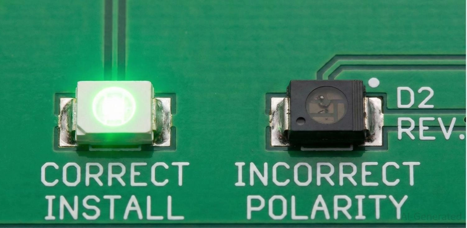
Figure: Properly installed SMD LED illuminating device compared to a non-functioning reversed SMD LED on a printed circuit board.
What Is SMD LED Polarity?
An LED is a semiconductor PN junction that allows electrical current to flow in only one specific direction.
Anode vs Cathode Explained
To understand SMD LED anode and cathode relationships, you must identify the two terminals:
● Anode (+): The positive terminal. Current enters the LED through the anode.
● Cathode (-): The negative terminal. Current exits the LED through the cathode.
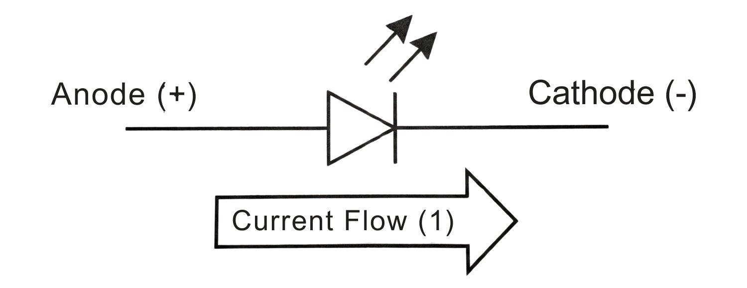
Figure: Standard LED schematic symbol highlighting the anode (positive) and cathode (negative) terminals.
How Current Flows in LEDs
For an SMD LED to emit light, it must be "forward-biased." The voltage at the anode must be higher than the cathode, exceeding the forward voltage ($V_f$) threshold (typically 1.8V–2.2V for red, and 2.8V–3.3V for blue/white). If reversed, the diode blocks current flow entirely.
SMD LED Polarity Identification Chart (Quick Reference)
Below is a quick-reference chart for common SMD LED packages and their standard polarity markings.
| Package Size (Imperial) | Metric Equivalent | Most Common Cathode (-) Marking | Top Marking Indicator |
|---|---|---|---|
| 0402 | 1005 | Green / Black dot or tiny line | Sometimes none (rely on the bottom) |
| 0603 | 1608 | T-shape or inverted "U" | Green dot or colored line |
| 0805 | 2012 | T-shape crossbar or line | Green triangle or line |
| 1206 | 3216 | T-shape, green line, or notch | Visible green band/ triangle |
| 3528 / 5050 | 3528 / 5050 | Missing corner (notch) | Notch in the plastic casing |
Pro Tip
When sourcing components, use the JLCPCB Parts Product Page to check the datasheets to verify your footprints before assembly.
How to Identify SMD LED Polarity in Detail?
As the absolute core of this guide, mastering how to identify SMD LED polarity is the single most important skill to prevent assembly failure. While component sizes and shapes vary, you can rely on these four primary methods for accurate SMD LED polarity identification.
Method 1: Polarity Markings on SMD LED Packages
The most direct method is visual inspection of the component's bottom pads. Because SMD LEDs are incredibly small, using a digital microscope or a jeweler's loupe is highly recommended. Look for a printed symbol, which is predominantly marked in green ink for high contrast against the metallic gold or silver pads:
● The T-Shape: This is the most universal marking. The horizontal top bar of the "T" represents the anode (+), while the vertical stem points directly to the cathode (-) pad.
● The Line, Band, or "U" Shape: A solid green line, a painted band, or a "U" shape clinging to one side of the bottom pad almost exclusively indicates the SMD LED cathode marking.
● The Triangle: If there is a triangle painted on the top or bottom, the narrow tip of the triangle points toward the cathode, mirroring the standard electronic diode symbol.
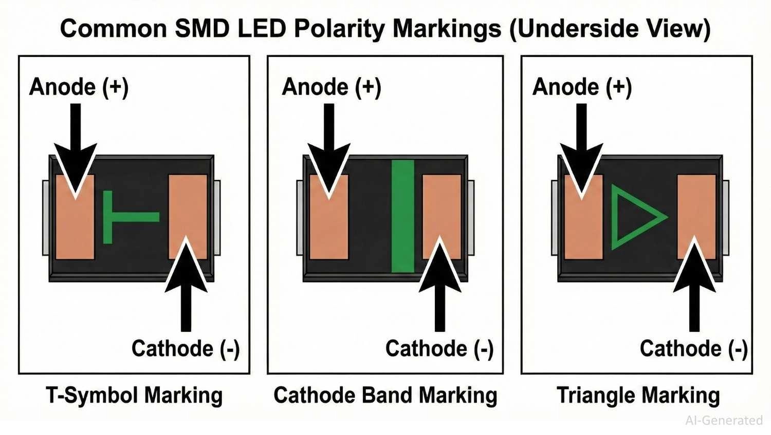
Figure: Common SMD LED polarity markings detailing the Anode (+) and Cathode (-) positions for the T-shape, solid cathode band, and triangle symbols.
Method 2: PCB Silkscreen and Footprint Indicators
Before soldering, the bare PCB provides critical orientation clues. The SMD LED polarity marking on PCB usually takes the form of a standard electronic diode symbol - a triangle pointing to a straight line. That straight line represents the cathode barrier.
Alternative silkscreen markings designed to guide assembly include:
● A thicker bounding box line is exclusively on the cathode side.
● Letters such as "C" or "K" (for Cathode) and "A" (for Anode).
● A small silkscreen dot next to Pin 1 (which usually aligns with the cathode, though datasheet verification is necessary).
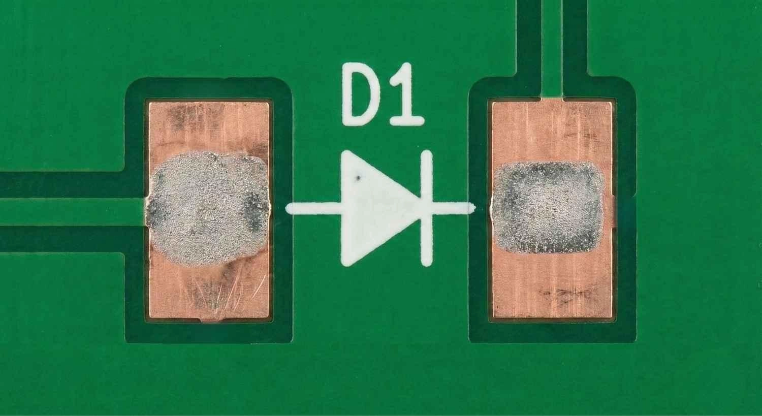
Figure: PCB silkscreen footprint for an SMD LED showing the standard diode symbol pointing toward the cathode pad.
Method 3: Using a Multimeter to Test SMD LED Polarity
When visual markings are faded, contradictory, or completely absent (as is common with microscopic 0402 packages), a digital multimeter is your definitive diagnostic tool. Here is the exact testing procedure:
1. Set the Multimeter: Turn your multimeter dial to the Diode Test mode (indicated by a small diode symbol). Do not use the continuity beeper mode.
2. Apply Probes: Place the Red probe gently on one metallic pad and the Black probe on the other.
3. Read the Screen:
○ If the meter reads "OL" (Open Loop) or "1", the diode is reverse-biased. The probes are backwards.
○ If the meter shows a voltage drop (typically between 1.8V and 3.0V, depending on the LED color) and the LED faintly illuminates, you have found the correct orientation.
4. Determine Polarity: The pad touching the Red probe is the Anode (+), and the pad touching the Black probe is the Cathode (-).
Note: Some standard multimeters only output 2.0V in diode mode, which may not be enough to illuminate blue or white LEDs (which often require ~3.0V). In these cases, look for the voltage drop reading on the screen even if there is no visible light.

Figure: Testing SMD LED polarity with a digital multimeter in diode mode, showing the red probe on the anode and black probe on the cathode.
Method 4: Checking Datasheets and Manufacturer Guides
While industry standards exist, they are not universal laws. Some specialized components, budget LEDs, or reverse-mount LEDs will flip these conventions entirely - sometimes using the green line to denote the anode instead of the cathode.
The component's official datasheet is the ultimate source of truth. Always navigate to the "Package Dimensions," "Mechanical Data," or "Pin Configuration" sections of the PDF to verify the physical polarity mapping before committing to a full assembly run.
Polarity Differences by SMD LED Package Type
Polarity markings vary drastically depending on the physical size and power requirements.
0402 / 0603 / 0805 / 1206 LEDs
Due to their small size, packages like the 0402 often omit complex top markings, relying solely on a tiny green dot or line on the bottom cathode pad. Use a magnifier for inspection. You can learn more about handling these sizes in this guide on surface-mount devices.
High-Power SMD LEDs
High-power LEDs (e.g., Cree, Osram) feature three pads: Anode, Cathode, and a central Thermal Pad. Polarity is often denoted by an asymmetrical thermal pad, a physical notch cut into the cathode side of the lead frame, or laser-etched "+" and "-" symbols.
RGB and Multi-Chip LEDs
RGB LEDs (5050 or 3528 format) pack three diodes into one package, featuring four or six pins. They come in Common Anode or Common Cathode configurations. The key marker is a chamfered (missing) corner on the plastic housing, which usually indicates pin 1.
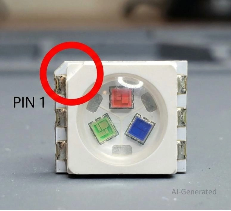
Figure: 5050 RGB SMD LED package highlighting the chamfered missing corner that indicates the starting pin.
PCB Design and Assembly Tips for Correct SMD LED Polarity
Design your PCB and assembly process so mistakes are mathematically impossible.
How to Mark SMD LED Polarity in PCB Footprints
● Include the standard diode symbol in the silkscreen layer, placed outside the component courtyard so it remains visible after soldering.
● Mark a prominent "K" or "-" near the cathode pad.
● Ensure pin 1 in your schematic symbol perfectly matches the footprint's primary polarity pin.
SMD LED Orientation in Pick-and-Place Assembly
In professional manufacturing, SMD LED orientation depends on the tape and reel packaging. The cathode is generally oriented toward the carrier tape's sprocket holes.
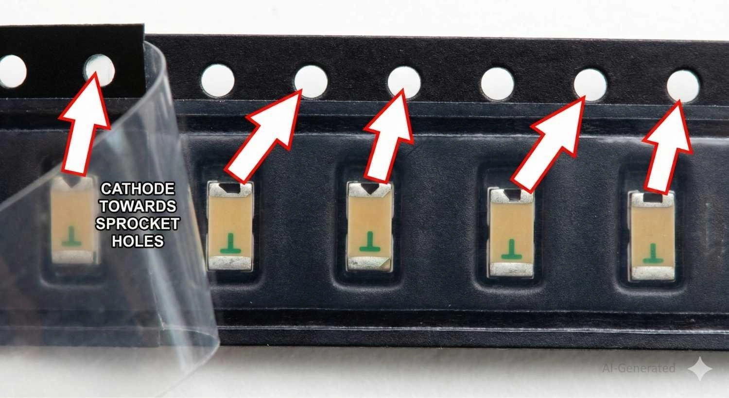
Figure: SMD LEDs inside carrier tape showing the cathode orientation aligning with the tape sprocket holes.
Manual Soldering Tips to Avoid SMD LED Polarity Errors
1. Organize LEDs on your bench with cathodes facing the same direction.
2. Apply high-quality flux.
3. Tack one pad, verify polarity with a magnifier, and solder the second pad.
Preventing SMD LED Polarity Issues in Mass Production
Ensure the rotation angles in your Centroid (Pick and Place) file align perfectly with the tape-and-reel orientation of your BOM part number. Reviewing the 3D DFM viewer on the JLCDFM Page can help catch inverted models before manufacturing.
Why Reversing SMD LED Polarity on PCBs Can Damage Your Circuit?
Reversing an LED doesn't just prevent light output; it can be destructive.
If placed in reverse polarity in a circuit exceeding the LED’s reverse breakdown voltage limit, the junction breaks down. This rush of backward current instantly burns out the diode, creating a short circuit. The shorted LED pulls excess current, permanently frying the driving microcontroller GPIO pin.
Furthermore, the rework cost and risk are high. Desoldering 0603 packages risks delaminating copper pads from the FR4 substrate. Designing robust footprints helps survive rework; learn more in this solder pad design guide.
Common SMD LED Polarity Errors and How to Fix Them
Misidentifying SMD LED Polarity Markings
● Problem: Assuming a green line always means cathode. Some obscure manufacturers use it to denote the anode.
● Fix: Always test one LED from a new batch with a multimeter before mass assembly.
Installing SMD LEDs with Wrong Polarity Orientation
● Problem: Discovering a backward LED after reflow soldering.
● Fix: Apply flux, use a hot air rework station at ~300°C with low airflow, and gently lift the component with tweezers. Let the board cool before placing a new LED.
Polarity Errors Caused by Mixed SMD LED Batches
● Problem: Loose LEDs from unverified vendors can result in mixed tape strips with alternating polarities.
● Fix: Source components from reliable distributors in continuous reels.
Incorrect PCB Footprints and SMD LED Polarity Symbols
● Problem: The CAD footprint maps schematic pins backward to the PCB footprint pads.
● Fix: Enforce strict library management. Consistently align Pin 1 to the Cathode across your CAD library.
FAQs about SMD LED Polarity
Q: Why Correct Polarity Matters in SMD LEDs?
Understanding surface mount led polarity ensures circuit safety. When installed backward, the LED blocks current. If the reverse voltage exceeds the threshold (usually ~5V), avalanche breakdown occurs.
This short-circuits the LED, potentially destroying the LED chip, the driving microcontroller pin, or the current-limiting resistor. Furthermore, reworking tiny SMD packages wastes time and risks damaging PCB pads.
Q: Which leg of an SMD LED is positive?
SMD LEDs do not have legs; they have pads. The positive pad (Anode) is generally the pad not marked by a green line, dot, or the tip of a T-shape.
Q: Is the green line on an SMD LED positive or negative?
In standard SMD LEDs, the green line, band, or dot printed on the bottom indicates the negative terminal (cathode).
Q: How do you find polarity on an SMD LED chip without a multimeter?
Flip the LED over with tweezers and look for a printed "T" shape. The top horizontal bar of the T is the anode (+), and the vertical stem points to the cathode (-). Alternatively, use a 3V coin cell battery to test orientation.
Q: Does the triangle marking on the top of an SMD LED point to the anode or the cathode?
The tip of the triangle printed on the top or bottom of an SMD LED points toward the cathode (negative) terminal, mimicking the standard diode symbol.
Q: Can a reverse-mount SMD LED have different polarity markings?
Yes. Reverse-mount LEDs sometimes have flipped polarity markings compared to standard top-emitting LEDs. Always refer to the datasheet.
Conclusion
Mastering SMD LED polarity is essential for any electronics designer. By recognizing visual markings (T-shapes, green cathode lines), utilizing multimeters in diode mode, and designing unambiguous PCB silkscreens, you can eliminate reverse-polarity errors.
When in doubt, always consult the component datasheet. To scale your project reliably and eliminate manual placement errors, consider JLCPCB's PCBA services. By sourcing directly from the massive JLCPCB Parts Library , you ensure that your exact LED models, orientations, and footprints are handled perfectly by state-of-the-art automated assembly lines from prototype to mass production.

Popular Articles
• How to Create a Bluetooth-Controlled Car With Arduino: A Step-by-Step Guide
• How to Design and Assemble a Reliable ESP32 Module PCB on a 2-Layer Board
• The Ultimate Guide to Relay Symbol: Coil, Contacts, Diagrams, and Circuit Applications
• How to Identify SMD LED Polarity: Markings, Testing, and PCB Tips
• The Ultimate Guide to PCBA: Process,Types and Techniques for the Electronics Enthusiast
Keep Learning
How to Design an ESP32-S3 Development Board from Scratch: A 4-Layer PCB Design Tutorial
Designing your own ESP32-S3 development board gives you complete control over your hardware architecture while preparing your IoT projects for commercial production. Instead of relying on bulkier, off-the-shelf boards, building a custom design allows you to optimize the board space, expose only the required GPIO pins, and integrate peripherals directly onto a single substrate. In this tutorial, we will design a 4-layer ESP32-S3 development board from scratch. We will walk through the entire hardware d......
Arduino LED Driver Tutorial: Control More LEDs with 74HC595 and MAX7219
Arduino GPIO pins run out quickly in larger LED projects. By utilizing dedicated LED drivers and expansion ICs, you can drastically reduce pin usage, eliminate processor-heavy multiplexing loops, and simplify display wiring. In this guide, you will learn the operational architecture, wiring configurations, cascading techniques, and optimization strategies for the 74HC595 shift register and the MAX7219 LED driver. Why Arduino Projects Need LED Driver ICs Arduino GPIO and Current Limitations An ATmega32......
How to Create a Bluetooth-Controlled Car With Arduino: A Step-by-Step Guide
This tutorial walks through the complete engineering and implementation of a two-wheel Bluetooth RC car with an Arduino Nano module on a specially designed PCBA (Printed Circuit Board Assembly). While many hobbyists start by wiring motors and Bluetooth modules with jumper cables on a breadboard, this approach is prone to disconnection and signal noise. This guide upgrades that process by teaching you how to design a professional mainboard. Key Design Features Controller: Arduino Nano used as a plug-in......
Fiducial Marks in PCB and SMT Assembly: A Complete Guide to Accuracy and Design Rules
Modern Printed Circuit Boards (PCBs) are complex, integrating high-density components like 0.4mm pitch Ball Grid Arrays (BGAs), 0201 passives, and fine-pitch Quad Flat No-Lead (QFN) packages. In this advanced manufacturing environment, achieving placement accuracy measured in micrometers is crucial. A significant challenge in automated manufacturing is how pick-and-place machines, which handle thousands of components per hour, precisely locate the PCB. A board on a conveyor system is never in the perf......
Alternating Current vs Direct Current (AC vs DC): What's the Difference?
Electric current flows in two primary forms: alternating current (AC) and direct current (DC). AC periodically reverses direction, while DC flows steadily in one direction. AC powers the industrial and residential electrical grids, while DC powers batteries, electric vehicles, and nearly all modern consumer electronics. Understanding the core differences between AC and DC matters when designing power supplies, selecting electronic components, or laying out printed circuit boards (PCBs). This guide com......
Arduino LED Multiplexing Tutorial: Control More LEDs with Fewer Pins
The Arduino Uno is a powerful tool for prototyping, but driving multiple LEDs directly quickly exhausts its 20 GPIO pins and its 200 mA absolute maximum package current limit. To bypass these hardware bottlenecks, engineers and hobbyists use LED multiplexing to scale display outputs efficiently without upgrading the microcontroller. In this guide, you will learn the core principles of LED matrix scanning, Charlieplexing, refresh timing, ghosting fixes, and practical Arduino code without relying on any......