Pin-in-Paste: Through-Hole Reflow With a Stencil
14 min
- Quick Answer: What Is Pin-in-Paste (PiP)?
- How Pin-in-Paste Works: One Reflow for SMT and Through-Hole
- When to Use Pin-in-Paste (and When Not to)
- The Core Pin-in-Paste Challenge: Filling the Barrel
- Pin-in-Paste Stencil Design: Overprint and Step Stencils
- The Reflow Profile for Pin-in-Paste
- Common Pin-in-Paste Defects (and How a Stencil Prevents Them)
- FAQ about Pin-in-Paste
- Conclusion: Making Pin-in-Paste Work on Your Board
Key Takeaways
One Reflow Process: Pin-in-paste combines SMT and through-hole soldering into a single reflow pass, eliminating the need for separate wave, selective, or hand-soldering steps when the board has only a few through-hole components.
Paste Volume Is Critical: Solder paste is roughly 50% flux by volume, so you need to print about twice the solder volume the finished joint requires. Stencil design—overprint apertures and step-up zones—makes or breaks the process.
Target 75% Barrel Fill: Per IPC-A-610 Class 2, aim for 75% vertical barrel fill, with a 50% minimum for certain holes on power/ground planes. Class 3 generally does not allow the exception.
Defects Are Preventable: Most PiP defects (insufficient fill, bridging, voids) trace back to paste volume. A well-designed stencil with proper overprint, step-up, and clean aperture release prevents the majority.
Your board is mostly SMT, but it still includes a few through-hole components, such as a connector or relay, where the mechanical strength of a plated hole is needed. Firing up a soldering iron or a wave machine just for those two parts feels like overkill.
This guide explains pin-in-paste (also known as intrusive reflow): how to solder through-hole parts in the same reflow pass as your SMT, what it takes to get it right, and where it tends to go wrong.
For general reflow-profile basics, see our reflow soldering guide; here we're focused specifically on the through-hole side.
Quick Answer: What Is Pin-in-Paste (PiP)?
Pin-in-paste, also known as intrusive reflow soldering, is a technique where solder paste gets stencil-printed into and around plated through-holes. The through-hole leads are inserted into that wet paste, and the whole board goes through a single reflow cycle, soldering SMT and through-hole components together with no separate wave, selective, or hand-soldering step needed.
A few things worth knowing up front:
- One reflow pass handles both SMT and through-hole (THT) parts, no wave step needed.
- The concept is simple. Getting enough paste into the barrel is the actual challenge.
- Overprint apertures and step-up stencils are the main tools for adding volume.
- Parts need to be reflow-safe (peaks near 260°C); dense or heat-sensitive ones may still need hand soldering.
- Target barrel fill is normally 75% per IPC-A-610; a 50% minimum applies for certain Class 2 holes, while Class 3 generally does not allow the exception.
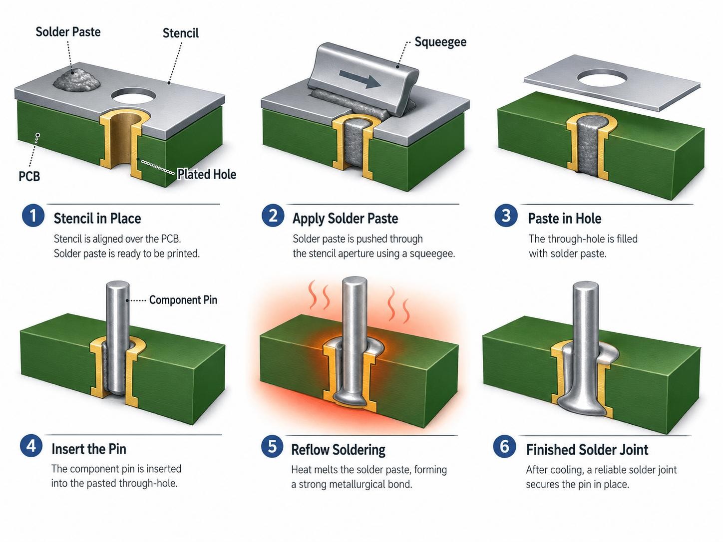
How Pin-in-Paste Works: One Reflow for SMT and Through-Hole
The mechanism itself isn't complicated. It comes down to three steps:
- Print the paste: a stencil prints solder paste into and around the plated through-hole (PTH) pad.
- Insert the component: the lead is placed or hand-inserted into the wet paste without displacing excessive material.
- Reflow the assembly: the board runs through the same oven as the rest of the assembly. As the solder melts, capillary action wicks it down through the barrel, wetting the lead and hole wall to form a fillet on both the top and bottom sides.
The Single-Pass Advantage
Folding through-hole soldering into the SMT reflow pass gets rid of a separate wave, selective, or hand-soldering step: one less machine on the line, a smaller footprint, fewer thermal cycles.
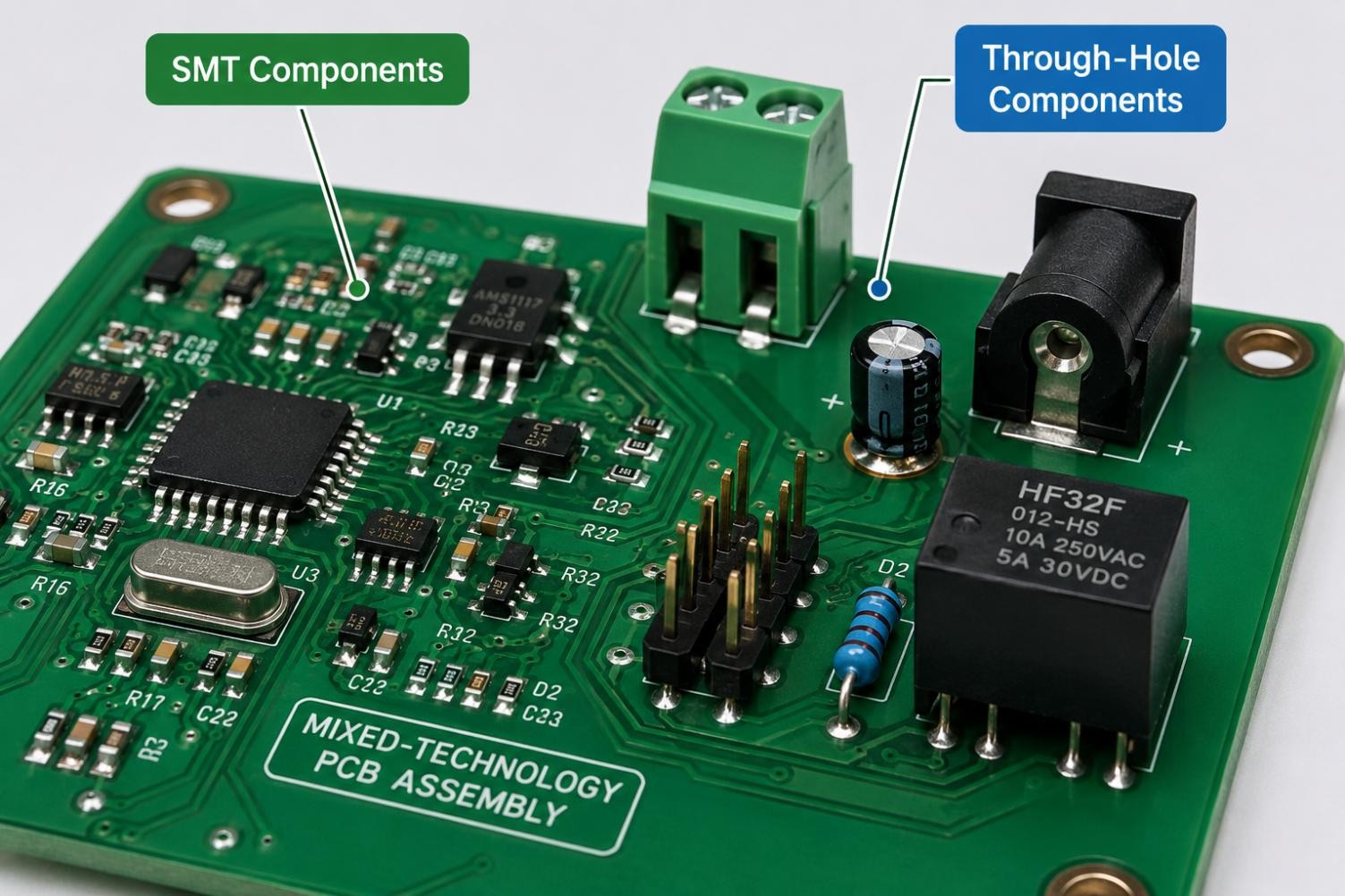
This makes through-hole reflow soldering practical for a mixed-technology PCB assembly with only a few PTH components, turning a two-stage process into a single reflow operation.
See our comparison of surface mount vs through hole for more.
When to Use Pin-in-Paste (and When Not to)
Good fits include boards that are mostly SMT with just a few through-hole parts, where mechanical strength matters more than saving board space:
- Headers, connectors, relays, transformers, and jacks needing a mechanically robust joint.
- Reflow-safe parts that survive a lead-free peak near 260°C without deforming.
- Round or square leads work best for PiP. Flat leads tend to displace paste unevenly and give inconsistent annular clearance. Also ensure enough clearance to print paste and insert the lead cleanly.
Poor candidates for through-hole reflow include:
- Heavy or heat-sensitive connectors, and dense areas with no room for overprint.
- Barrels too large for a realistic paste volume, where selective or hand soldering is the better call.
The Core Pin-in-Paste Challenge: Filling the Barrel
Every pin-in-paste decision comes down to one number: how much solder ends up in the barrel. Solder paste is roughly 50% flux by volume, and that flux volume is largely lost during reflow, so the paste shrinks by about half as it turns into solid solder.
In practice, this means you need to print roughly twice the solder volume the finished joint actually requires. Some residue may remain depending on the paste type, so treat this as a starting approximation rather than an exact ratio.
Set the barrel-fill target according to the applicable IPC-A-610 revision, product class, and customer requirements.
Barrel-fill acceptance depends on the applicable IPC standard and revision (such as IPC-A-610 or IPC J-STD-001), product class, and application requirements.
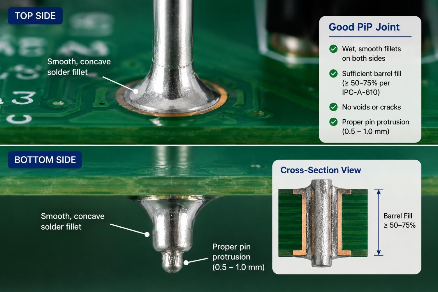
Class 2 specifications commonly reference 75% vertical fill as a target, with a 50% minimum for certain holes connected to power or ground planes. Class 3 requirements are stricter and generally do not permit the 50% exception. Always confirm against the governing spec for your board.
A few design levers determine how close a joint gets to that target:
- Lead-to-hole clearance: commonly around 0.20–0.25 mm (8–10 mil) diametrical clearance, though the final value depends on plating, tolerances, and paste volume needed. Too tight blocks paste; too loose costs mechanical support.
- Lead protrusion: typically 0.5–1.0 mm (20–40 mil) below the board, enough to form a visible fillet without excess.
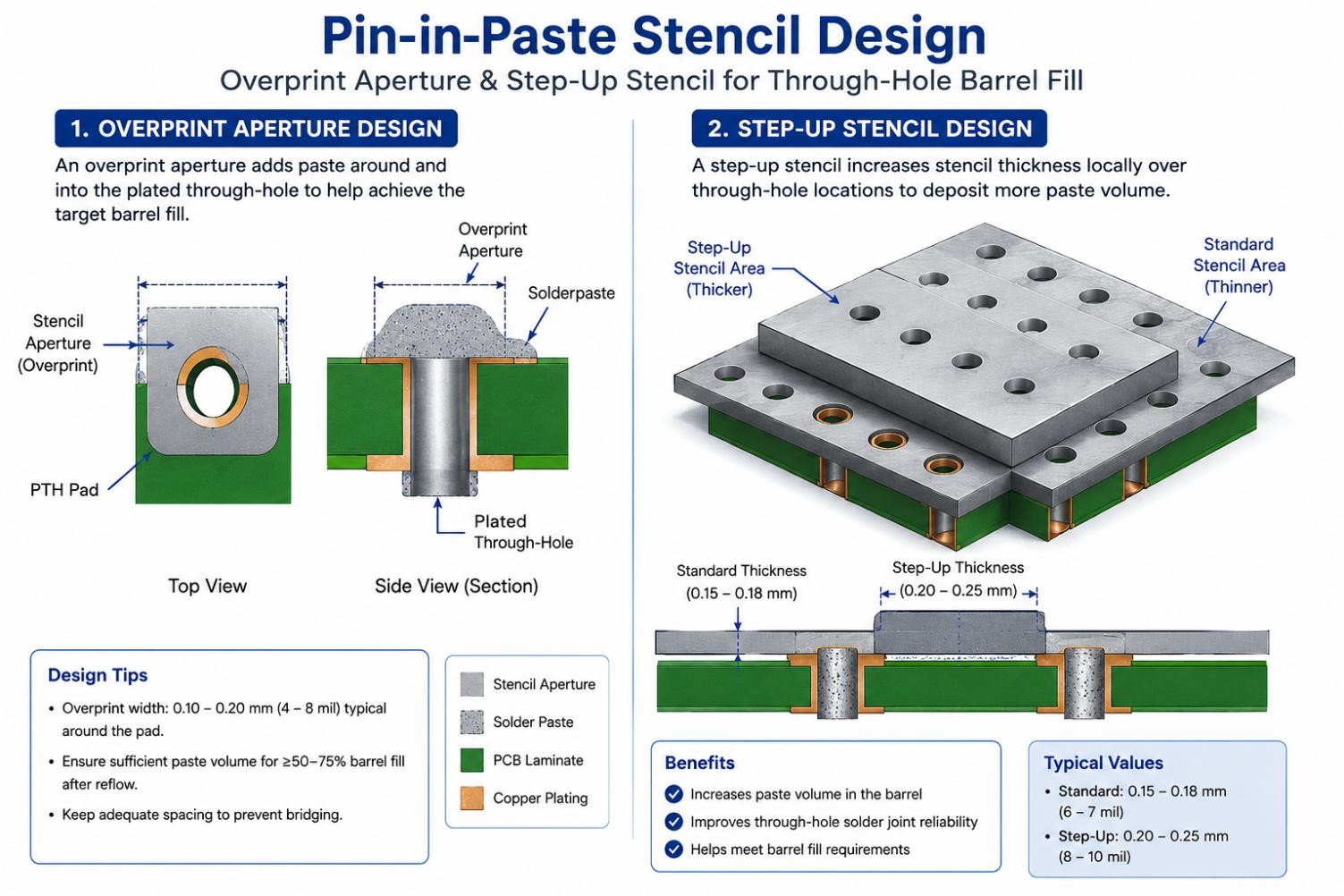
- Stencil thickness: usually 0.15–0.2 mm (6–8 mil) for through-hole reflow (THR) work, thicker than a typical fine-pitch SMT stencil.
A Basic Paste-Volume Calculation
To size the paste deposit, start from the solder actually needed in the finished joint, not the paste itself.
Required solid solder volume = barrel annulus volume at the target fill + top and bottom fillet volume
Required printed paste volume = required solid solder volume ÷ metal volume fraction ÷ expected transfer efficiency
For the barrel portion alone:
Barrel Solder Volume = (π ÷ 4) × (Dhole2 - Dlead2) × Tboard × Fill Target
Paste is roughly 50% metal by volume, and stencil transfer efficiency is never 100%, so the printed deposit ends up considerably larger than the final metallic joint.
Indium's PiP volume guidance works through this relationship for specific hole and lead geometries using its StencilCoach method.
Pin-in-Paste Stencil Design: Overprint and Step Stencils
Turning that math into an actual stencil comes down to three techniques: overprint apertures, step-up zones, and clean aperture release.
Overprint Apertures
The most direct way to add paste volume is to print the aperture past the pad's edge, out onto the solder mask. That's called an overprint.
During reflow, solder de-wets from the low-energy mask surface and is pulled by surface tension into the barrel, adding to the fill.
Overprint has limits. Push it too far and paste can bridge into a neighboring aperture, or bead up on the mask instead of wicking in.
A well-designed stencil keeps overprint sized to the actual shortfall and respects keep-out spacing from nearby apertures.
Step-Up Stencils for Extra Volume
Sometimes overprint alone can't deliver enough paste. A deep barrel, a thick board, or a connector with closely spaced pins can outrun it.
A step-up stencil adds a locally thicker zone of foil over the through-hole area, without dumping extra paste on the fine-pitch SMT nearby. The key is a controlled, gradual step height with enough keep-out distance from any nearby apertures.
JLCPCB offers step-stencil capability for a locally thicker deposit over a PiP area, subject to footprint spacing and manufacturing review.
Our guide to step-up and step-down stencils covers how those zones are designed.
Aperture Optimization and Clean Release
Overprint and step-up zones only help if paste can release from the aperture cleanly—a challenge governed by the aperture aspect ratio and area ratio guidelines in IPC-7525. Rough aperture walls, poor squeegee release, or an aperture never opened for a through-hole pad will undercut even a well-designed overprint.
Many fabricators, including JLCPCB, only open a through-hole aperture if the pad sits on the paste layer of your Gerber set, an easy detail to miss.
Define your overprint and step-up geometry in the manufacturing data and confirm it during CAM review; JLCPCB's stencil opening-process standard covers this. Its stencils are laser-cut from 304 stainless steel to roughly ±0.003 mm (±0.12 mil) accuracy, with electropolishing and nano-coating for cleaner release.
See our guide on how to choose a solder paste stencil for more on matching specs to your board.
Solder Preforms When PiP Isn't Enough
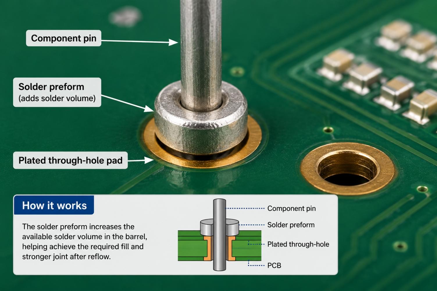
For high-volume barrels (thick boards, large holes, high-current connectors), printed paste sometimes can't carry enough metal even with overprint and a step-up zone together. A solder preform, a small stamped washer or chip-sized segment of solid solder near 100% metal by volume, can go into the paste before the lead is inserted to add the extra mass needed. Indium's StencilCoach and AIM's PiP process guidance offer design tools for these volume relationships.
The Reflow Profile for Pin-in-Paste
A through-hole joint carries more paste mass and sits in thicker copper and laminate than a typical SMT pad, so it heats up more slowly.
That may call for adjustments to soak, conveyor speed, peak temperature, or time above liquidus (TAL), so the barrel fully wets without pushing nearby SMT parts past their limits.
There's also outgassing to consider: a bigger paste deposit means more flux volatiles need to escape before liquidus, and a rushed preheat leaves trapped gases to show up as voids or solder beads.
Thermal relief spokes on PTH pads tied to large copper pours keep the pad from acting like a heat sink, and keeping tall components clear of the through-hole area avoids shadowing it.
AIM's process guidance recommends validating the final profile with thermocouples rather than one universal adjustment.
Our reflow soldering guide covers the underlying preheat, soak, and cooling mechanics in full.
Common Pin-in-Paste Defects (and How a Stencil Prevents Them)
Most pin-in-paste defects come back to one root cause: too much or too little paste reaching the barrel.
| Defect | Likely Cause | Stencil-Side Fix |
|---|---|---|
| Insufficient barrel fill | Not enough paste reached the hole | Bigger overprint, a step-up zone, or a solder preform |
| Bridging or shorts | Too much paste, or apertures placed too close together | Tune overprint size; respect keep-out spacing |
| Voids | Flux gas trapped by a preheat that ran too fast | Extend soak time; keep volume proportional to need |
| Solder beads or excessive flux residue | Overprinted paste beading on the mask instead of wicking in | Adjust overprint geometry; check mask finish |
| Floating or skewed neighbors | A step-up zone over-pastes nearby fine-pitch SMT | Balance step height against nearby paste needs |
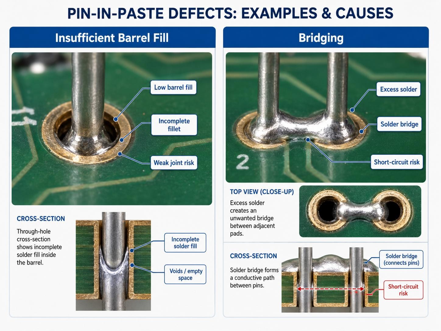
Correct aperture, overprint, and step design prevent many of these before reflow. For broader defect patterns, see solder paste printing defects.
Our how to prevent solder defects during reflow soldering guide covers profile-driven defects.
FAQ about Pin-in-Paste
Can Pin-in-Paste Be Hand-Inserted, or Does It Need a Pick-and-Place Machine?
Both manual and automated insertion can work. Machine placement makes sense when the pick-and-place head can handle a part's height and weight. Plenty of pin-in-paste boards still use hand insertion after the SMT stage, especially for connectors too tall or oddly shaped for automated placement. Either way, the paste is already printed, so insertion method doesn't change how the joint forms.
Does Pin-in-Paste Work With Standard Lead-Free Solder Paste?
Often, yes, but confirm it rather than assume it. A qualified SAC305 paste can frequently be used, provided its technical data sheet supports the selected profile and application. Run a trial print and first-article reflow to confirm transfer efficiency, wetting, flux activity, residue, and voiding before committing to production. Barrel-fill outcomes still depend more on stencil design than on paste chemistry.
How Do I Tell My Assembler I Want Pin-in-Paste Instead of Wave or Hand Soldering?
Flag it explicitly rather than assuming it happens by default. Make sure your through-hole pads sit on the solder paste layer of your Gerber or ODB++ output, since without that entry, most stencil makers won't open an aperture for the pad. Note which parts should be pin-in-paste in your order remarks, and confirm the overprint and step-up geometry during CAM review.
Can Pin-in-Paste and Wave or Selective Soldering Coexist on the Same Board?
Yes, and it's fairly common on boards mixing reflow-safe and reflow-unsafe parts. Connectors rated for the applicable lead-free peak go through pin-in-paste with the rest of the SMT reflow, while anything that can't survive that thermal exposure, like certain electrolytic capacitors, gets selective or hand soldered afterward. This hybrid approach still reduces how many parts need a separate soldering stage.
Does a Pin-in-Paste Joint Hold Up as Well Mechanically as a Wave-Soldered One?
A properly designed and qualified PiP joint can achieve mechanical and electrical performance comparable to other through-hole methods when it meets the applicable workmanship and reliability requirements. Both rely on similar barrel-fill and wetting principles for acceptability. Fill quality is what separates them: a wave machine floods the hole with molten solder, more forgiving of marginal paste volume than a stencil print.
What Is the Largest Through-Hole Barrel Pin-in-Paste Can Realistically Fill?
There is no universal maximum hole diameter. Feasibility depends on board thickness, finished-hole and lead dimensions, target fill, overprint area, stencil thickness, paste-transfer efficiency, pin pitch, and whether solder preforms are permitted. Large power connectors and thick boards tend to push against these limits first, which is usually where preforms or a hybrid wave or selective approach make more sense.
How Do You Inspect Barrel Fill After Reflow?
Start with a visual check for a visible, concave fillet on both the top and bottom of the board; a flat or missing fillet signals underfill. First-article verification on a new design should include a cross-section or X-ray of a sample joint to confirm actual fill against the specified IPC class, since visible fillets alone don't guarantee the barrel is filled internally.
Conclusion: Making Pin-in-Paste Work on Your Board
Pin-in-paste merges through-hole and SMT soldering into a single reflow pass, and the process lives or dies on one variable: whether enough solder paste reaches the barrel.
That's fundamentally a stencil-design problem, overprint sized to the hole and a step-up zone where overprint falls short, plus clean aperture release, paired with a profile tuned for the extra thermal mass.
Get the stencil and the profile right, and pin-in-paste turns two soldering steps into one. Explore JLCPCB's PCB stencil manufacturing capabilities for the full range of options on your next mixed-technology build.
Keep Learning
Low-Temperature Solder Paste: A Practical Sn-Bi Guide
Key Takeaways Sn42Bi58 is the mainstream low-temp alloy and melts at 138 C. Typical reflow peak is 165 to 180 C, about 25 to 30 C above the melt. It protects heat-sensitive components and reduces warpage on large, thin boards. It enables step soldering, because 165 to 180 C will not remelt SAC305 joints. Bismuth joints are more brittle than SAC305, so avoid drop-critical products. Never mix Sn-Bi with leaded (Sn-Pb) solder. Bi, Sn and Pb form a ternary eutectic that melts near 95 C. Some parts and som......
Pin-in-Paste: Through-Hole Reflow With a Stencil
Key Takeaways One Reflow Process: Pin-in-paste combines SMT and through-hole soldering into a single reflow pass, eliminating the need for separate wave, selective, or hand-soldering steps when the board has only a few through-hole components. Paste Volume Is Critical: Solder paste is roughly 50% flux by volume, so you need to print about twice the solder volume the finished joint requires. Stencil design—overprint apertures and step-up zones—makes or breaks the process. Target 75% Barrel Fill: Per IP......
Mixed Technology PCB Assembly: Combining SMT and THT on One Board
As technologies become increasingly more complex, the demand for sophisticated printed circuit boards continues to rise. In the electronics industry, the two most prevalent PCB Assembly technologies are SMT and THT, which differ mainly in the manner at which the components are attached. SMT places the components on the surface of the board whereas THT makes use of drilled holes to solder components. While these technologies individually cater to specific applications, advancements in the electronics i......
Moisture Sensitivity Level (MSL): Baking Guide
Key Takeaways Moisture Sensitivity Level (MSL) is a 1-6 classification under IPC/JEDEC J-STD-020 that indicates how quickly a non-hermetic surface-mount package can absorb enough moisture to become vulnerable during reflow. MSL 1 has unlimited floor life at its reference condition, while MSL 6 requires baking before use and reflow within the time printed on the caution label. The floor-life clock begins when the moisture barrier bag is opened and exposure to factory air starts. Baking according to IPC......
Understanding SMT Stencil Printers for Accurate PCB Solder Paste Printing
Stencil printing is a critical process in SMT (Surface Mount Technology) assembly, significantly impacting the quality and reliability of solder joints on PCBs. The crucial machine for implementing this is the SMT Stencil Printer, which applies an appropriate measure of solder paste to each pad of the PCB board before it goes to the placement of components. For those of you looking to work out what a stencil printer is and why it matters in manufacturing, you've come to the right place. This is the ba......
Surface Mount Stencil: A Practical Guide for SMT Printing and Solder Paste Application
It starts with a slim piece of metal, slipped in early during assembly. Before any part lands in place, before heat ever touches the board, that layer shapes the flow. Where the paste spreads comes down to its design. How thick it is, how it's cut - those details decide what sticks and what washes away. For engineers looking for reliable stencils, JLCPCB provides high-precision SMT stencils that integrate seamlessly with PCB production workflows. Down goes solder paste, slipping through narrow cuts in......