Reading Motor Symbols: Common Types, IEC/ANSI Conventions & Typical Circuit Examples
13 min
- Motor Symbol Chart
- Motor Types and Their Symbols
- Telling Apart Motor, Generator, Servo, and Stepper Symbols
- What Does a Motor Symbol Mean?
- Motor Symbol Pinouts: Armature, Field, and Power Terminals
- IEC vs. ANSI/IEEE Motor Symbols: What's the Difference?
- How to Read a Motor Symbol in a Schematic Step by Step
- FAQs About Motor Symbols
- Conclusion
Key Takeaways
⬇ Download the Free Motor Symbols Cheat Sheet (PDF)
- First find the basic designator: a circle marked M is a motor, a circle marked G is a generator, and the leads coming out of the circle are the connection terminals.
- Two drafting standards exist: IEC and ANSI/IEEE schematics differ slightly in appearance but represent the same class of motor, with windings and terminals marked in the same way.
- Read the auxiliary marks: use annotations such as AC/DC, ~, and 3~ to judge AC/DC type and phase count; armature, field winding, and brush/commutator marks help identify brushed construction and excitation form.
- Know which types share one symbol: ordinary DC and AC motors usually use the standard circled-M symbol; servo, stepper, BLDC motors, and generators each have recognizable dedicated forms.
- Check the datasheet: the symbol itself usually does not state rotation direction, polarity, or terminal definition; confirm both in the datasheet before designing the circuit and PCB layout.
A motor symbol can appear in several forms within the same design. The basic drawing is a circle labeled M; a DC motor may carry a field winding and brush marks alongside; servo, stepper, BLDC motors, and generators use their own dedicated designators.
Even when the basic circled symbol is the same, a different connection between the field winding and armature (series, shunt, or compound) changes the actual wiring and operating characteristics.
In this guide, you will learn:
- The common motor symbol variants summarized in one chart.
- How to identify armature terminals, field windings, and brush/commutator marks.
- How IEC and ANSI/IEEE motor symbols differ.
- How to tell a DC motor, AC motor, generator, servo, and stepper apart.
- Which motor types have their own dedicated symbol.
Motor Symbol Chart
Most motor symbols use a circle as the body, with a motor designator inside, and distinguish the type through winding, phase count, and auxiliary marks. Each variant changes one detail: the body letter, winding form, number of leads, or control/feedback interface. Once the schematic is finished, you can bring your design to production with JLCPCB's PCB fabrication and assembly services.
⬇ Download the Free Motor Symbols Cheat Sheet (PDF)
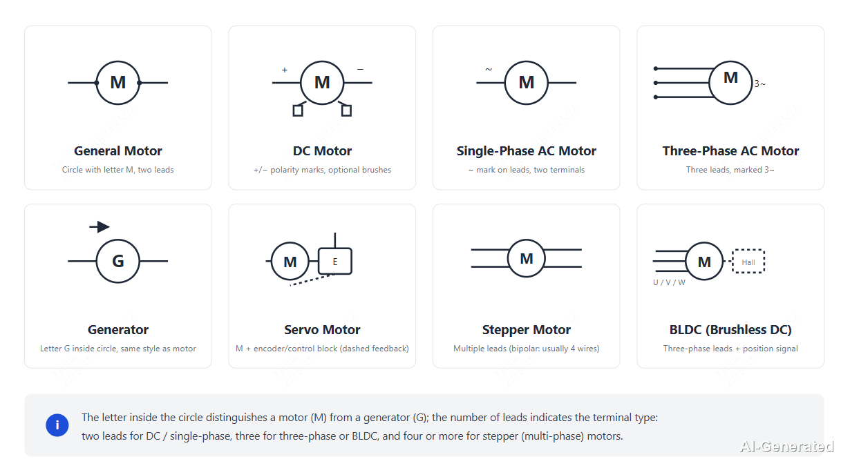
Figure: Motor symbol chart — 8 common motor symbols with type names and key features.
| Symbol Variant | Drawing | Terminals | Description |
|---|---|---|---|
| Generic motor (standard) | Circle labeled M, with power/armature leads | 2 or more | Converts electrical energy into mechanical energy |
| DC motor | Circle M with a field winding alongside | Armature + field terminals | DC supply; excitation method determines operating characteristics |
| Single-phase AC motor | Circle M, marked AC or ~ | 2 power terminals | Driven by single-phase AC |
| Three-phase AC motor | Circle M, marked 3~, three groups of terminals | Three-phase terminals | Three-phase induction or synchronous motor |
| Generator | Circle labeled G | 2 output terminals | Converts mechanical energy into electrical energy |
| Servo motor | Circle habitually marked SM or Servo, with control and feedback leads | Power + control/feedback terminals | Closed-loop position or speed control |
| Stepper motor | Circle M, phase windings brought out separately | 4/6 phase terminals | Driven step by step by pulse signals |
| Brushless DC motor (BLDC) | Circle M, three-phase winding with driver interface | Three-phase + control terminals | Electronic commutation, brushless construction |
What Do Labels Such as M1, DC, and 3~ Mean?
The label beside a motor symbol gives the designator, current type, and phase count; rated voltage, power, and speed are usually written in the annotation field or on the nameplate, not drawn into the symbol.
| Label | Meaning | Where It Appears |
|---|---|---|
| M1, M2 | Motor designator; M = Motor, numbering distinguishes multiple motors | Schematic designator field |
| G1, G2 | Generator designator; G = Generator | Schematic designator field |
| DC | DC supply mark (not a motor code) | Symbol annotation |
| AC, ~ | Single-phase AC motor | Symbol annotation |
| 3~ | Three-phase AC motor | Symbol annotation |
| SM / Servo | Habitual servo marking, not a mandatory standard drawing | Circle designator or annotation |
| A, B | Phase winding marks on a stepper motor | Phase terminal annotation |
Motor Types and Their Symbols
Ordinary DC and AC motors usually share the standard circled-M symbol; servo, stepper, BLDC motors, and generators each have a recognizable form because they add a control interface, feedback mechanism, or dedicated winding. You can search for suitable motor and driver parts, or review the PCBA assembly capabilities.
- Shared standard symbol: ordinary DC motor, single-/three-phase AC motor
- Own symbol form: generator, servo motor, stepper motor, brushless DC motor
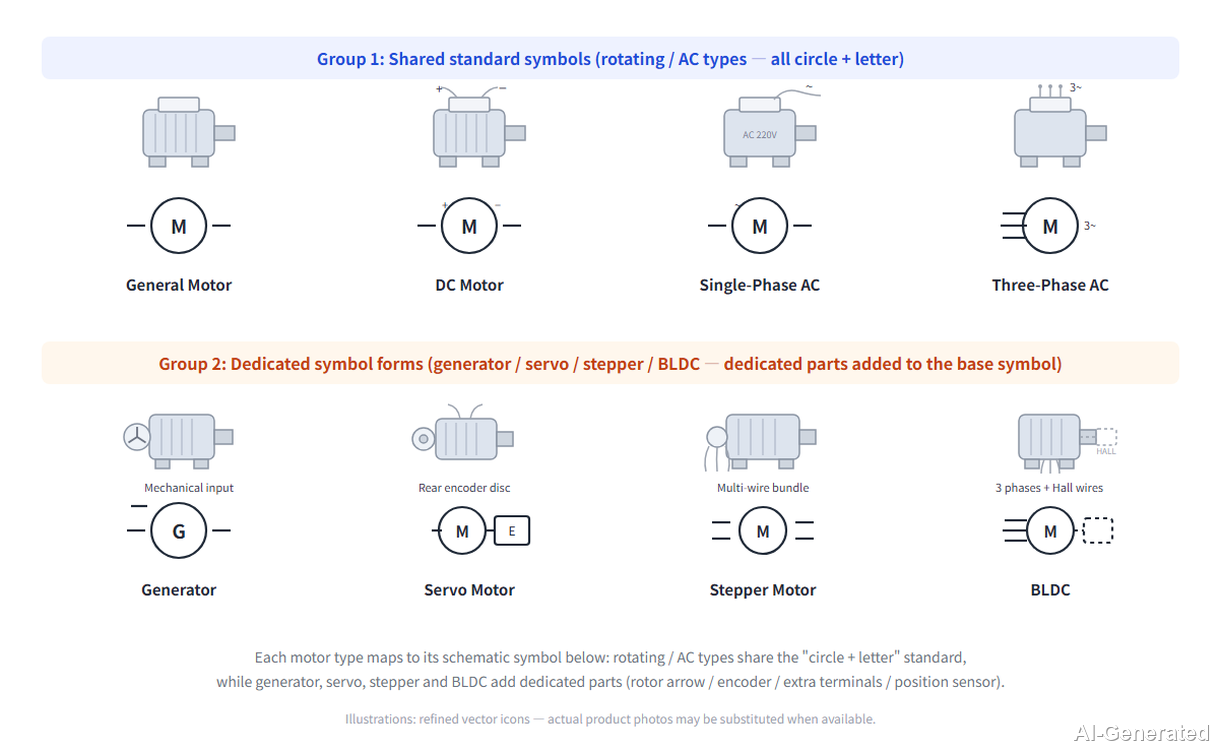
Figure: Motor types and their symbols — standard symbols (rotating/AC) vs dedicated symbol forms (generator, servo, stepper, BLDC).
1. DC Motor Symbol
A DC motor consists of an armature (rotor) and field winding. By the connection between field and armature, it is classified as series, shunt, or compound, with separately excited as a separate case (the field is supplied from an independent source):
- a series winding is in series with the armature for high starting torque;
- a shunt winding is in parallel with the armature for steadier speed;
- a compound motor carries both series and shunt windings.
The symbol uses a circled M with the corresponding field winding alongside; whether a brush/commutator mark appears depends on the drafting convention.
2. AC Motor Symbol
A single-phase AC motor is usually marked AC or ~ with two power terminals; a three-phase AC motor is marked 3~ with three line terminals, common in induction and synchronous motors.
The winding form (squirrel-cage, wound rotor) is generally not shown in the symbol; check the motor nameplate and datasheet.
3. Generator Symbol
The generator symbol has the same outline as the motor, but the circle is labeled G and the leads are electrical outputs. Judge direction from the circuit: a machine supplying a load is a generator; one driven by the supply is a motor.
4. Servo Motor Symbol
A servo motor is used for closed-loop position or speed control. Besides power terminals, the symbol carries control signal leads and an encoder feedback lead; a dashed line often shows the mechanical or electrical link to the controller.
Some drawings habitually mark SM or Servo inside the circle; this is not a mandatory standard drawing.
5. Stepper Motor Symbol
A stepper motor converts pulses into angular step motion; its windings are brought out by phase, commonly two-phase four-wire or two-phase six-wire (with center tap). Each phase winding is drawn separately; phase order and tap definition follow the datasheet.
6. Brushless DC Motor (BLDC) Symbol
A BLDC motor replaces brushes with electronic commutation. The symbol usually shows a three-phase winding connected to a drive controller; feedback elements such as Hall sensors appear as additional marks.
Telling Apart Motor, Generator, Servo, and Stepper Symbols
Read in this order: check the circle letter to decide motor vs. generator, then the leads and windings for AC/DC and phase count, and finally the control and feedback leads to identify dedicated types such as servo and stepper.
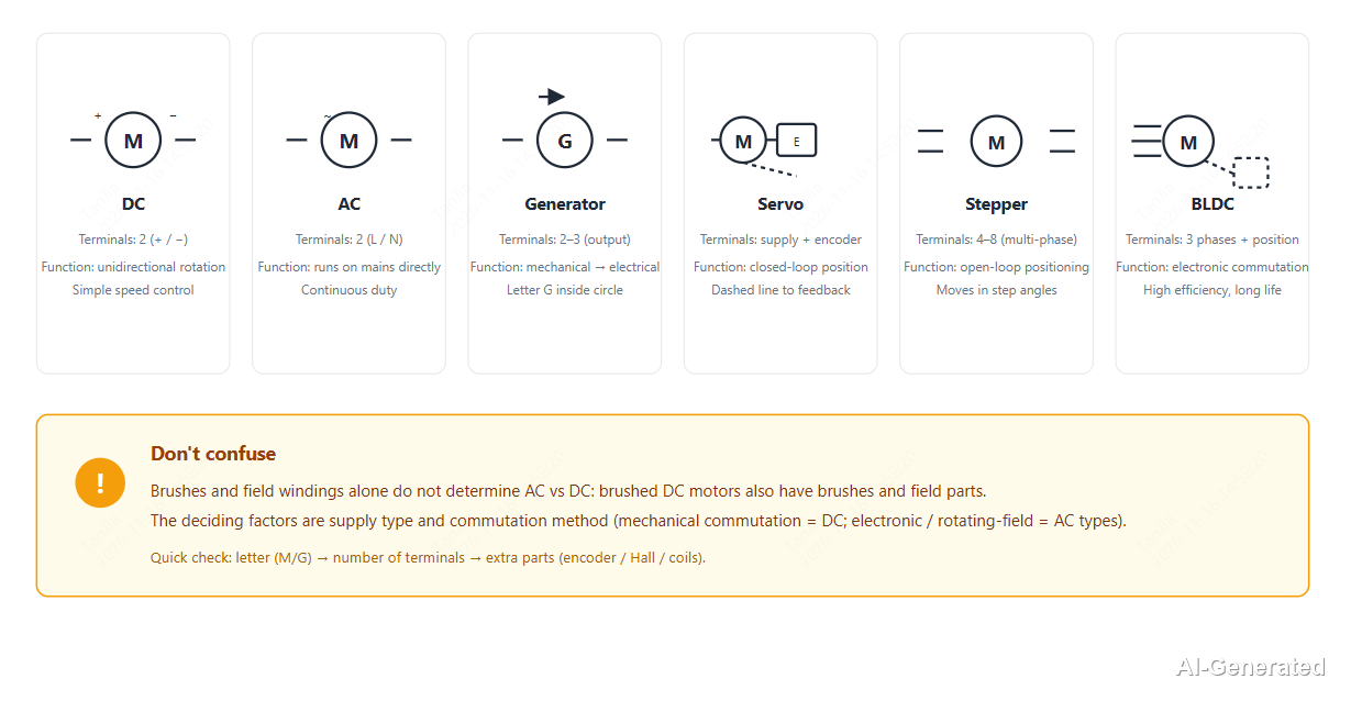
Figure: How to tell motor, generator, servo, stepper and BLDC symbols apart — terminals and circuit function.
| Symbol | Drawing | Terminals | Function in the Circuit |
|---|---|---|---|
| DC motor | Circle M, may carry a field winding | Armature + field terminals | DC supply; torque and speed can be adjusted through the excitation method |
| AC motor | Circle M, marked AC/~ or 3~ | Single-phase 2-wire or three-phase 3-wire | Driven by AC; commonly used in fans, pumps, conveyors |
| Generator | Circle G | Output terminals | Converts mechanical energy to electrical energy and supplies the circuit |
| Servo motor | Circle habitually marked SM/Servo, with control and feedback leads | Power + control/feedback terminals | Closed-loop position or speed control |
| Stepper motor | Circle M, phase windings brought out separately | 4/6 phase terminals | Open-loop positioning in pulse steps |
| Brushless DC motor (BLDC) | Circle M, three-phase winding to a driver | Three-phase + control terminals | Electronic commutation, brushless construction |

Once your motor driver design is finalized and passes the necessary DFM checks, export your Gerber files and upload them to JLCPCB for an instant fabrication quote.
What Does a Motor Symbol Mean?
A motor symbol represents a rotating device that converts between electrical and mechanical energy.
The circle is the motor body; the letter inside states whether it is a motor or generator; the leads correspond to actual connection terminals; the side windings and marks further indicate supply type and excitation form.
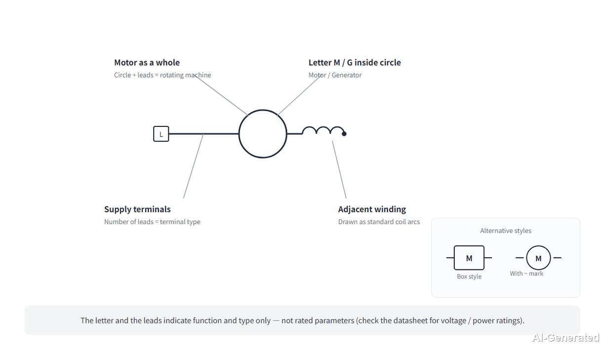
Figure: Motor symbol with terminals and excitation marks
Each element of a motor symbol corresponds to a physical part:
- Circle body: the complete motor; its rotating part is the rotor (called the armature in DC motors). Rated voltage, power, and speed shown alongside are drawing annotations, not part of the symbol itself.
- Letter inside the circle: M = Motor, G = Generator; dedicated types such as servo and stepper carry their own designators.
- Leads: connection points to the supply, field winding, or control circuit; the number of terminals varies by motor type.
- Side winding and marks: indicate excitation method, phase count (single/three-phase), and AC/DC type; a brush mark denotes brushed construction.
Motor Symbol Pinouts: Armature, Field, and Power Terminals
A plain two-wire motor connects straight to the supply; a separately excited DC motor also brings out field winding terminals; a three-phase motor has three line terminals. Which terminal connects to the supply and which to the field is defined in the datasheet.
| Terminal | Symbol Element | Function | Verify in Datasheet |
|---|---|---|---|
| Armature/power terminal | Main lead from the circle | Connects to the drive supply or outputs power | Terminal number, polarity (DC), phase sequence |
| Field winding terminal | Lead from the side winding | Carries field current (separately excited motor) | Series/shunt/compound connection |
| Phase terminal | Multiphase winding brought out separately | Connects to each phase drive signal | Phase sequence, whether a center tap is brought out |
| Control/feedback terminal | Additional leads on servo/stepper | Receives control signals or returns encoder feedback | Control level, feedback type, interface definition |
Motors usually carry one of these reference designator prefixes, followed by a number such as M1:
- M: the most common prefix for a motor (Motor).
- G: generator (Generator).
- SM: a habitual servo-motor marking in some drawings, not a mandatory style; prefixes for stepper and BLDC motors vary by drafting convention.
When selecting parts, browse the JLCPCB Parts Library to check available motors and driver modules and their footprints.
IEC vs. ANSI/IEEE Motor Symbols: What's the Difference?
Unlike resistors and potentiometers, the motor body uses a circle in both IEC 60617 and ANSI/IEEE 315.
The two standards differ mainly in winding drawing, letter marking, and how auxiliary mechanisms are shown; the basic meaning is the same.
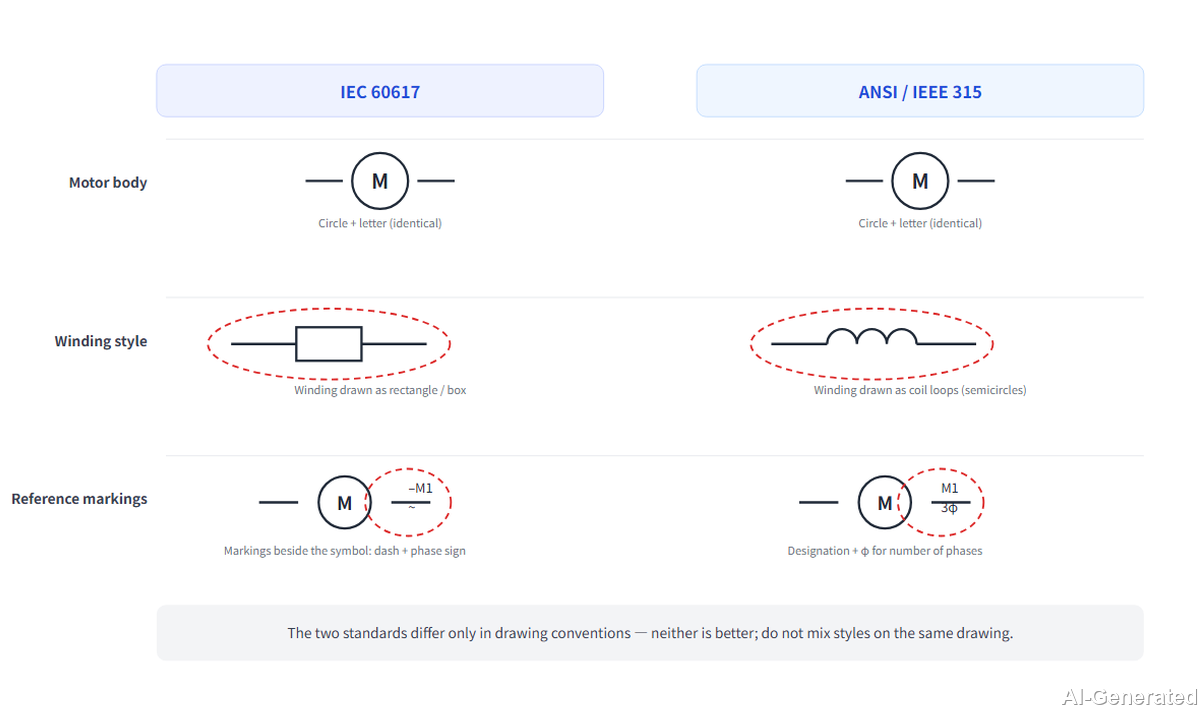
Figure: IEC circle drawing vs. ANSI/IEEE motor symbol comparison.
| Detail | IEC 60617 Style | ANSI/IEEE 315 Style | Meaning When Reading |
|---|---|---|---|
| Motor body | Circle with a letter designator | Same circle; letter-marking habits differ slightly | Represents the same motor body |
| Winding drawing | Field winding and armature drawn with standard winding symbols | Winding details slightly simplified | Represents the same set of field/phase windings |
| Auxiliary marks | Defined symbols for brushes and mechanical links | Common simplified equivalents | Indicate brushes, interlocks, or feedback mechanisms |
How to Read a Motor Symbol in a Schematic Step by Step
Read a motor symbol in a fixed order: body and letter first, then power terminals, then trace the field and phase windings, and finally check the control leads and labels.
The example below contains a single-phase AC fan, a DC separately excited motor, and a stepper motor.
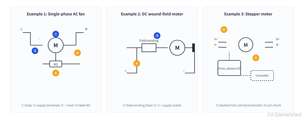
Figure: Motor symbol reading example (AC fan, DC motor, stepper motor).
Step 1: Identify the body: M in the circle is a motor, G is a generator; a plain single set of power terminals is usually an ordinary AC or DC motor.
Step 2: Find the power terminals: the main lead to the drive supply is the armature/power terminal; note polarity for DC and phase sequence for three-phase.
Step 3: Trace the field winding: a winding in series with the armature is series, in parallel is shunt, and both present means compound.
Step 4: Check auxiliary marks: a brush mark denotes brushed construction; extra feedback leads correspond to an encoder or Hall sensor.
Step 5: Check dashed links: a dashed line to a controller, brake, or interlock switch means a mechanical or control association.
Step 6: Read the label and verify pins: after confirming AC/DC, phase count, phase marks, and designator, check terminal definition, polarity, and phase sequence against the datasheet before layout.
FAQs About Motor Symbols
What Do the Letter and Leads Inside the Motor Symbol Mean?
The circle is the complete motor; M inside means motor, G means generator; the leads correspond to power, field, or control terminals, and the terminal count varies by motor type.
What Is the Difference Between a Motor and a Generator Symbol?
Both use a circle; the difference is the circle letter: M for motor, G for generator. The actual direction must be judged from the circuit: driven by the supply is a motor; delivering electrical energy to the load is a generator.
How Do I Tell a DC Motor Symbol From an AC Motor Symbol?
Use the annotation as the primary criterion: marked DC is a DC motor; marked AC or ~ is single-phase AC; marked 3~ with three groups of terminals is three-phase AC. Field winding and brush marks are auxiliary only and cannot alone determine AC vs. DC.
How Are Servo and Stepper Motors Drawn in a Schematic?
A servo adds control and feedback leads to the standard circle, often marked SM or Servo; a stepper brings out each phase winding separately (commonly 4 or 6 wires), with phase designators such as A and B beside the terminals.
Where Do I Confirm Terminal Definition, Rotation Direction, and Polarity?
The symbol itself usually does not state these; rely on the motor datasheet and nameplate. Verify DC polarity, three-phase sequence, and servo/stepper phase and control interfaces one by one before wiring and PCB layout.
Conclusion
A motor symbol uses a circle as the body: the letter marks a motor (M) or generator (G); leads correspond to power, field, or control terminals; side windings and marks indicate excitation method, phase count, and AC/DC type.
The symbol only shows how the part connects in the circuit; it cannot reflect every parameter of the physical part. Identifying the motor type is the first step; before designing the PCB and wiring, checking the datasheet for actual pins, polarity, phase sequence, rotation direction, and footprint is just as important.
Popular Articles
• Power Supply Symbols Chart: A Complete Guide to AC, DC, Ground, Battery, and Source Symbols
• How to Design and Assemble a Reliable ESP32 Module PCB on a 2-Layer Board
• How to Identify SMD LED Polarity: Markings, Testing, and PCB Tips
• Logic Gate Symbols: The Complete Chart, Truth Tables [2026]
• The Ultimate Guide to Relay Symbol: Coil, Contacts, Diagrams, and Circuit Applications
Keep Learning
Understanding Thyristor Symbols: A Schematic Guide for PCB Design
Key Takeaways One family, several related symbols: Most thyristor symbols are based on a diode-like structure, with additional graphical features used to indicate the gate, bidirectional operation, or other device characteristics. The gate indicates how the device is controlled: A gate identifies a gate-controlled thyristor, while additional gate markings can distinguish devices with turn-off capability. Thyristor-family devices without a gate may switch when a specified voltage or other triggering co......
Op Amp Symbol Explained: Pinout, Polarity, and Power Pins
The op amp symbol is one of the most common shapes in analog schematics: a triangle with two inputs and one output. Reading it correctly, knowing which pin is inverting, which is non-inverting, and how power connects, is the first skill needed before building any amplifier circuit. Standard op amp symbols include a non-inverting input, an inverting input, an output, and power supply connections that may be shown or hidden depending on schematic style. The common symbol convention uses a triangle with ......
Power Supply Symbols Chart: A Complete Guide to AC, DC, Ground, Battery, and Source Symbols
Note ⬇ Download the Power Supply Symbols Cheat Sheet [PDF] Keep the most common power supply symbols, standards, and meanings at hand. Get the free PDF for quick reference while designing or reviewing schematics. Power supplies are one of the most fundamental parts of electronic circuits. When reading a schematic, you may encounter different power-related symbols, including AC sources, voltage supplies, and ground references. Although some symbols look simple, each one represents a specific electrical......
Diode Symbol Guide: Meaning, Types & Circuit Diagram Examples
The diode symbol is the visual language engineers use to represent how a diode controls current flow in a circuit. Think of a diode as a one-way street for your electronics. It acts like a valve that allows electrical current to flow freely in one direction. The schematic symbol is basically a visual map that perfectly illustrates this one-way traffic! What you will learn in this guide: Identify anode and cathode (polarity) Understand forward vs reverse bias Learn common types of diode symbols See rea......
Reading Motor Symbols: Common Types, IEC/ANSI Conventions & Typical Circuit Examples
Key Takeaways ⬇ Download the Free Motor Symbols Cheat Sheet (PDF) First find the basic designator: a circle marked M is a motor, a circle marked G is a generator, and the leads coming out of the circle are the connection terminals. Two drafting standards exist: IEC and ANSI/IEEE schematics differ slightly in appearance but represent the same class of motor, with windings and terminals marked in the same way. Read the auxiliary marks: use annotations such as AC/DC, ~, and 3~ to judge AC/DC type and pha......
How to Design and Assemble a Reliable ESP32 Module PCB on a 2-Layer Board
Many engineers fail when designing their first ESP32 PCB due to antenna issues, power instability, or SMT defects. Designing a custom board with an ESP32 Module strikes the perfect balance between customizability and ease of manufacturing. Unlike a chip-down design, the module integrates the crystal oscillator, flash memory, and RF matching network, reducing the PCBA risk significantly. the SMD package (for example, ESP32-S2-WROOM modules) introduces several assembly considerations, including pad sold......