Understanding Thyristor Symbols: A Schematic Guide for PCB Design
17 min
- Thyristor Symbol Chart (Quick Reference)
- What Is a Thyristor Symbol?
- Anatomy of an SCR Symbol: Anode, Cathode, and Gate
- Thyristor Types and Symbols
- Common Thyristor Symbol Mistakes to Avoid
- SCR vs. TRIAC vs. DIAC vs. GTO: Symbol Comparison
- IEC vs. ANSI: Thyristor Symbol Differences
- How to Identify Thyristor Terminals From a Symbol
- How to Identify Thyristor Terminals From the Package
- Conclusion
- FAQs About the Thyristor Symbol
Key Takeaways
- One family, several related symbols: Most thyristor symbols are based on a diode-like structure, with additional graphical features used to indicate the gate, bidirectional operation, or other device characteristics.
- The gate indicates how the device is controlled: A gate identifies a gate-controlled thyristor, while additional gate markings can distinguish devices with turn-off capability. Thyristor-family devices without a gate may switch when a specified voltage or other triggering condition is reached.
- IEC 60617 includes standardized thyristor symbols: Section 05-04 covers thyristor-related graphical symbols and their conventions.
- The symbol does not define the physical pinout: Always check the datasheet. For example, a BT151 may have a different pin arrangement from a BT169D, even though both use thyristor symbols.
The thyristor symbol can look simple, but it actually represents a whole family of power devices. The thyristor family contains devices such as SCRs, TRIACs, DIACs, GTOs, SCSs, and LASCRs, each with its own symbol and switching behavior.
An SCR resembles a diode symbol with a gate terminal, while a TRIAC is represented by two opposing thyristor structures. A DIAC has no gate and uses a different bidirectional symbol. When several of these devices appear on the same schematic, their symbols can be easy to confuse at a glance.
Knowing how to read these symbols correctly helps you identify the intended device before selecting a component or assigning a PCB footprint.
In this guide, you will learn:
- Common thyristor symbols, including SCR, TRIAC, DIAC, GTO, SCS, and LASCR
- How to distinguish an SCR from a TRIAC
- How to identify the anode, cathode, and the gate from the symbol
- How IEC and ANSI/IEEE conventions represent thyristor devices differently
Thyristor Symbol Chart (Quick Reference)
IEC 60617-5 includes a range of thyristor symbols for circuit diagrams. The 10 symbols below cover common thyristor types and configurations.
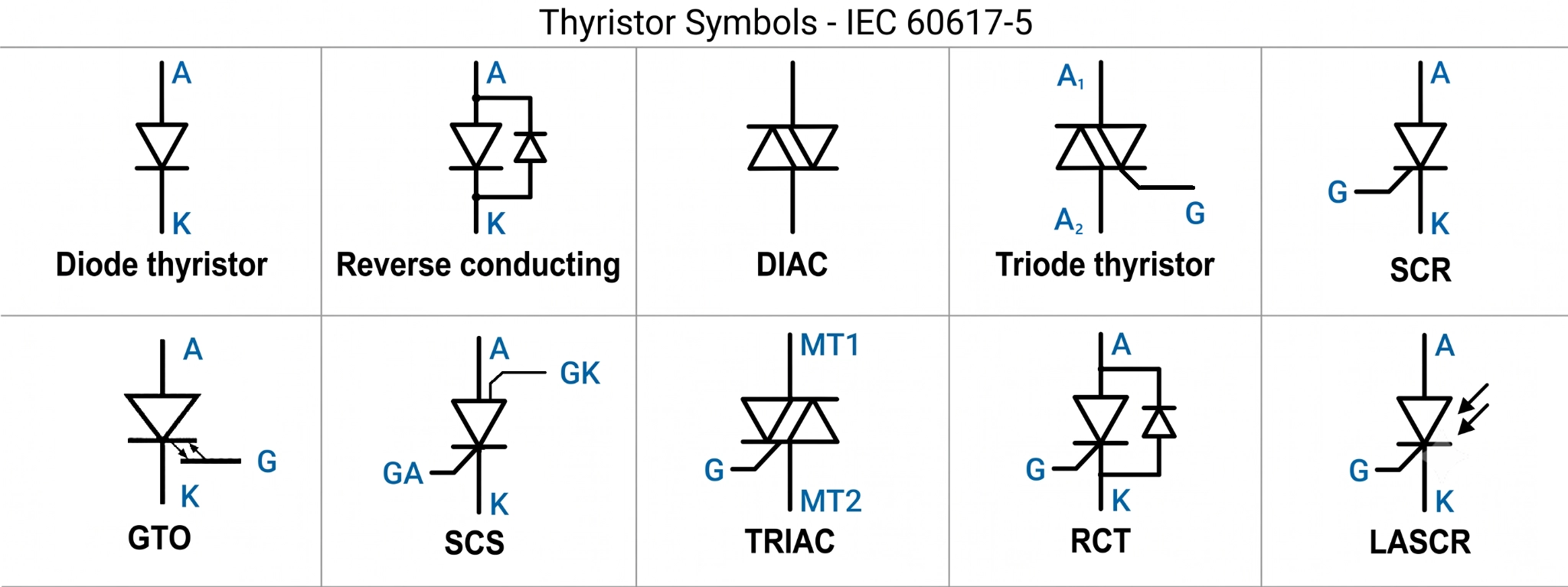
Figure: The complete thyristor symbol chart
| Symbol Name | Device | Terminals | Conducts | Gate Control | IEC 60617-5 Entry |
|---|---|---|---|---|---|
| Reverse blocking diode thyristor | Shockley four-layer diode | A, K | Forward only | None, fires at breakover | 05-04-01 |
| Reverse conducting diode thyristor | Diode thyristor, built-in reverse path | A, K | Forward, reverse clamped | None | 05-04-02 |
| Bidirectional diode thyristor | DIAC | MT1, MT2 | Both ways | None, fires at breakover | 05-04-03 |
| Triode thyristor, gate unspecified | Generic thyristor | A, K, G | Forward only | Gate on | 05-04-04 |
| Reverse blocking triode thyristor, N gate | Anode-gate SCR | A, K, G | Forward only | Gate on | 05-04-05 |
| Turn off thyristor, gate unspecified | Generic GTO | A, K, G | Forward only | Gate on and off | 05-04-07 |
| Reverse blocking tetrode thyristor | SCS, two gates | A, K, anode gate, cathode gate | Forward only | Cathode gate on, anode gate off | 05-04-10 |
| Bidirectional triode thyristor | TRIAC, BT136 | MT1, MT2, G | Both ways | Gate on, either polarity | 05-04-11 |
| Reverse conducting triode thyristor, gate unspecified | Generic RCT | A, K, G | Forward, reverse clamped | Gate on | 05-04-12 |
| Light-activated triode thyristor | LASCR | A, K, G optional | Forward only | Light fires it | No entry, radiation arrows |

Once the symbol, footprint, and pin order are verified, move from design to production with JLCPCB. Choose from 116443+ thyristors and TRIACs in the parts library, then upload your Gerber and BOM to get an instant quote for PCB manufacturing and SMT assembly.
What Is a Thyristor Symbol?
A thyristor symbol represents a semiconductor device designed for controlled switching and latching conduction.
An SCR symbol resembles a diode because an SCR conducts primarily in one direction, while the added gate terminal indicates controlled triggering. A suitable gate current pulse can trigger an SCR into conduction; once latched, removing the gate drive normally does not turn it off. The SCR remains on as long as its anode current stays above the holding-current level.
The symbol tells you four important things before you even look at the part number:
- It is primarily a switch: A thyristor is designed to control current between blocking and conducting states rather than provide linear amplification.
- It can latch on: A suitable trigger pulse can turn an SCR on, after which it remains conducting as long as the required current continues to flow.
- The gate is a trigger, not a throttle: Removing the gate signal does not normally turn an SCR off once it has latched.
- It has a holding current: When the SCR's anode current falls below its specified holding current, the device can return to the off state.
Note
If you are new to schematic symbols, see the full circuit symbols reference, which covers other common electrical and electronic devices.
Anatomy of an SCR Symbol: Anode, Cathode, and Gate
The SCR symbol is the basic form used to identify a conventional thyristor. It has three terminals—anode (A), cathode (K), and gate (G)—and each terminal represents a specific electrical function.
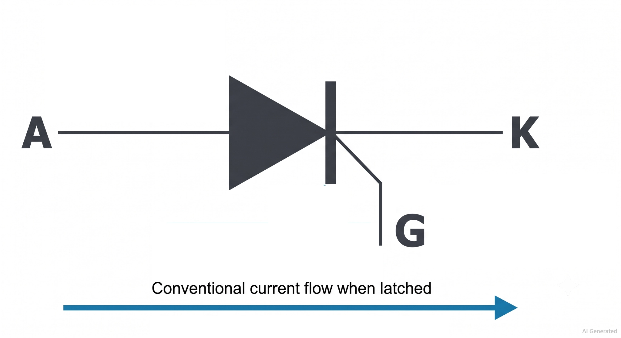
Figure: SCR symbol showing anode, cathode, gate terminal, and the direction of conventional current flow.
- The Diode-Like Body: The SCR uses a diode-like symbol with the anode (A) on one side and the cathode (K) on the other. The cathode is identified by the bar, as in a standard diode symbol. Conventional current flows from anode to cathode when the SCR is conducting.
- The Gate Terminal: The third terminal is the gate (G), drawn beside the cathode side of the symbol. A positive gate current relative to the cathode triggers a conventional SCR into conduction. This extra terminal is what distinguishes the controlled thyristor from an ordinary diode.
Why the Gate is referenced to the Cathode: In a conventional SCR, the gate is electrically referenced to the cathode because the gate controls the device through the gate-cathode junction.
The gate driver, therefore, needs to provide the correct gate-to-cathode voltage and current. Always check the manufacturer's datasheet for the actual gate-drive requirements and physical pinout.
SCR Two-Transistor Model: How Latching Works
Split the four-layer PNPN structure in the middle, and you can think of it as a PNP transistor coupled to an NPN transistor, with each transistor feeding the other’s base. That positive feedback loop is what gives the SCR its latching behavior: a short gate pulse can trigger regenerative action, pushing the device into conduction and allowing it to remain in conduction as long as the anode current stays above the holding-current level.
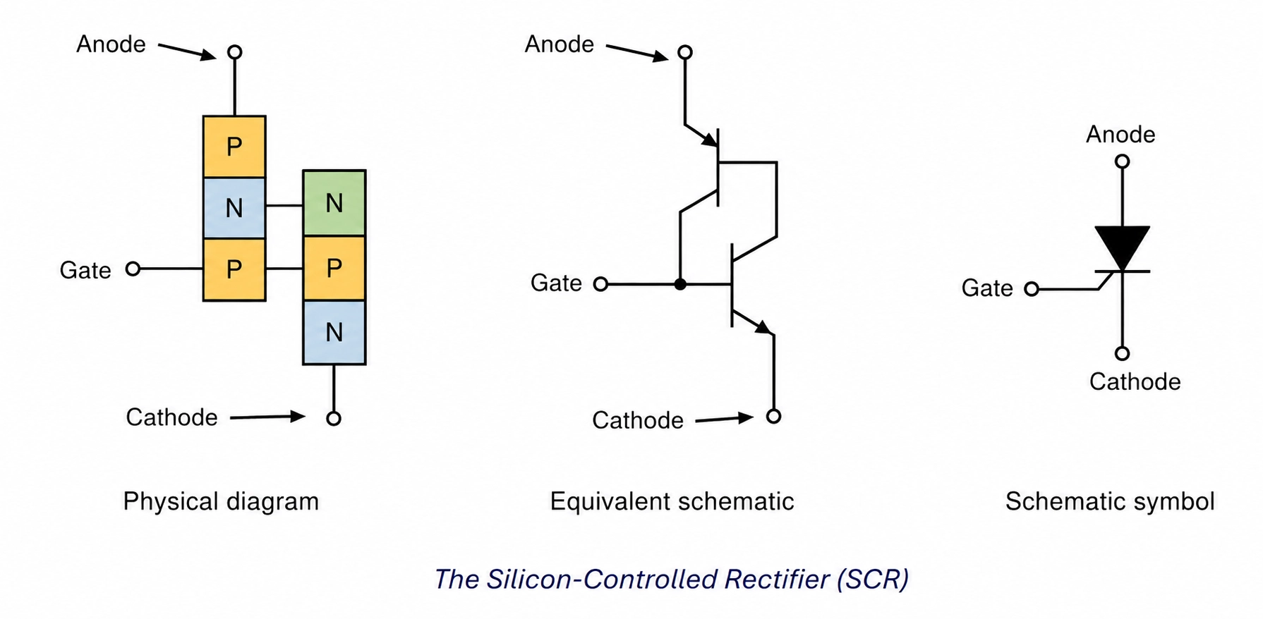
Figure: The two-transistor analogy, showing the PNPN stack of SCR
The symbol itself, however, does not show the electrical limits that determine when the device switches. Breakover voltage can trigger the SCR without a gate signal, while holding current determines when the device turns off after latching.
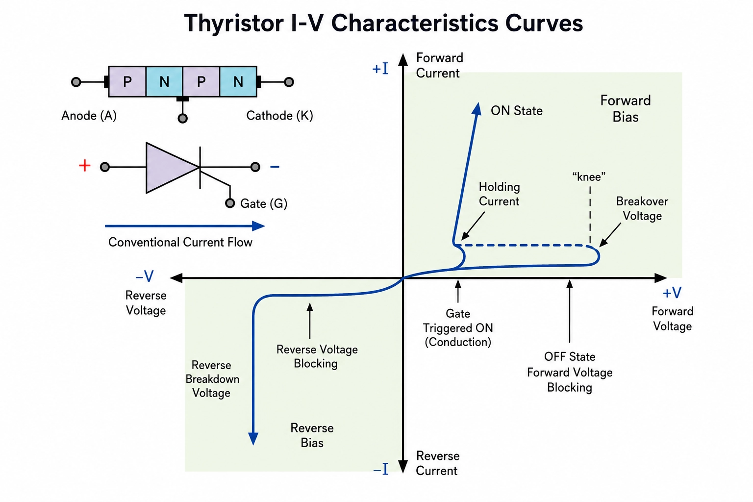
Figure: SCR I-V characteristic
Thyristor Types and Symbols
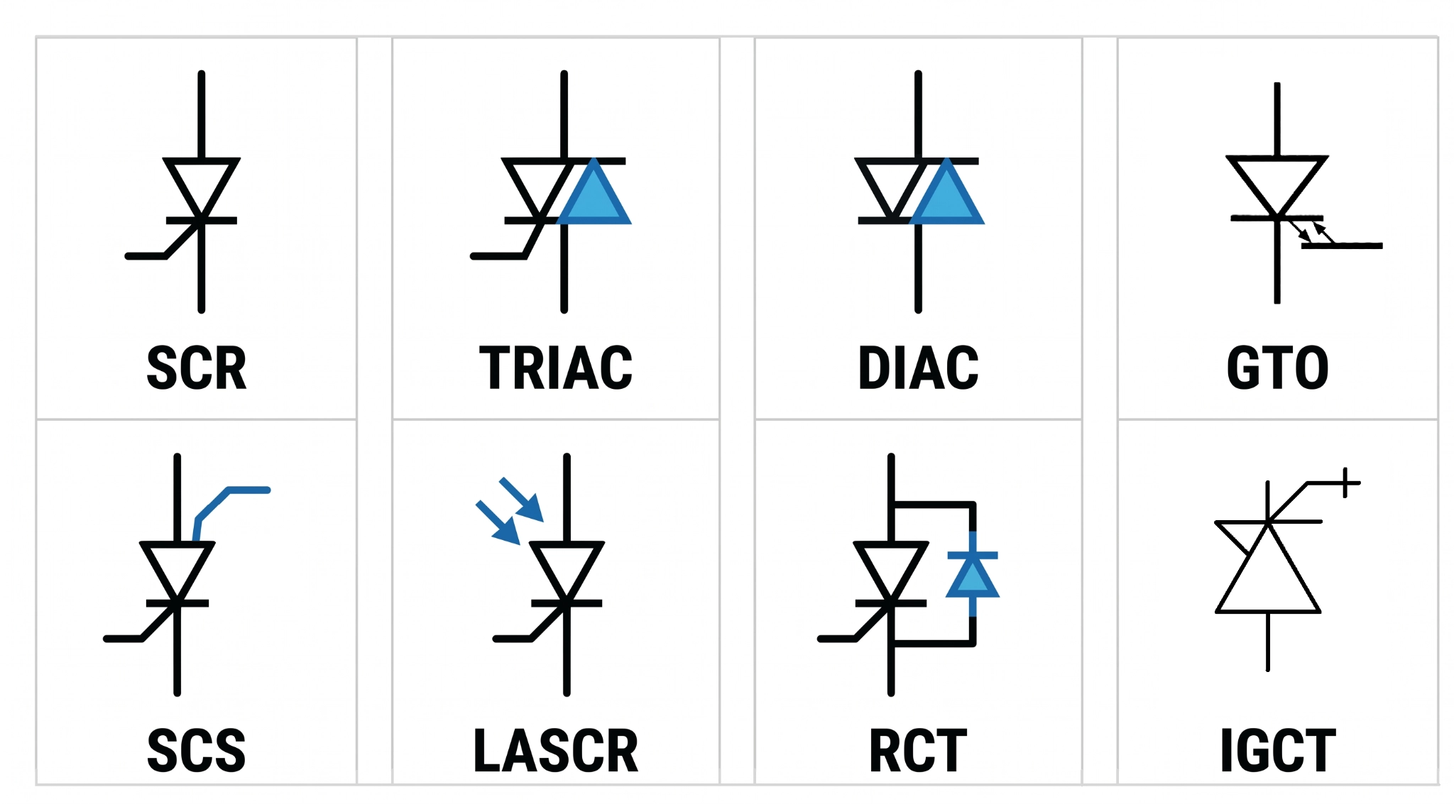
Figure: SCR, TRIAC, DIAC, GTO, SCS, LASCR, RCT, and IGCT Symbols
SCR Symbol — Silicon Controlled Rectifier
One diode-like body, one gate terminal, and three terminals marked A, K, and G.
An SCR normally remains forward-blocking until a suitable gate trigger initiates conduction, although forward breakover can also trigger conduction.
After latching, the SCR can turn off when its anode current falls below the holding-current level.
TRIAC Symbol — Bidirectional Triode Thyristor
The TRIAC symbol represents bidirectional thyristor action, with two main terminals and a gate. The main terminals are called MT1 and MT2 rather than anode and cathode because current can flow in either direction.
A TRIAC can be understood functionally as two SCRs connected in anti-parallel, although that does not mean it is physically just two conventional SCRs placed together. Its gate behavior is described by four triggering quadrants, with sensitivity depending on the polarity of MT2 and the gate's position relative to MT1.
DIAC Symbol — Bidirectional Diode Thyristor
A DIAC is a two-terminal bidirectional trigger device with no gate. Its symmetrical symbol indicates bidirectional operation, indicating that it can conduct in either direction once its breakover voltage is reached.
The absence of a gate is the important detail: the DIAC is triggered by applied voltage, not by an external gate pulse. A common example is the DB3, typically used as a trigger device for TRIAC circuits.
GTO Symbol — Gate Turn-Off Thyristor
A GTO resembles an SCR but has a gate designed for both turn-on and turn-off control. A suitable positive gate current triggers conduction, while a sufficiently large reverse gate current can force the device off.
Unlike an SCR, a GTO requires a substantial gate-current pulse to turn off. The gate driver, therefore, has to handle much more demanding current than a conventional SCR trigger circuit.
SCS Symbol — Silicon Controlled Switch
An SCS is a four-terminal thyristor with separate anode-gate and cathode-gate connections in addition to the anode and cathode. These two gate terminals provide greater control over the device than the single gate of a conventional SCR.
The extra gate terminal is the key feature to look for when identifying an SCS symbol.
LASCR Symbol — Light-Activated SCR
A LASCR is an SCR that can be triggered by incident light. The symbol adds optical arrows pointing toward the semiconductor structure to indicate light activation.
Depending on the particular symbol convention, a gate terminal may still be shown. Do not confuse a LASCR with an optocoupler or opto-triac: a LASCR is a light-triggered thyristor, whereas an optocoupler combines an optical transmitter and receiver in an isolation package.
RCT Symbol — Reverse-Conducting Thyristor
An RCT combines a thyristor with an anti-parallel diode, providing a reverse-current path through the device.
The diode is particularly useful in power-converter circuits where reverse current is required, such as certain inductive-load and inverter applications.
IGCT Symbol — Integrated Gate-Commutated Thyristor
An IGCT is a high-power thyristor designed for rapid turn-off through an integrated, low-inductance gate-drive arrangement. Its symbol emphasizes the thyristor and its gate-control connection rather than implying that a separate rectangle physically represents the complete gate-driver electronics.
IGCTs are used in high-power applications such as medium-voltage drives and industrial converters, where high voltage, high current, and fast turn-off capability are required.
Other Thyristor-Related Trigger Devices
A few related devices may also appear in thyristor symbol charts:
- SIDAC: A bidirectional breakover device that operates similarly to a DIAC but is designed for higher-energy switching applications.
- SBS: A silicon bilateral switch that provides a relatively well-defined bidirectional switching threshold.
- SUS: A silicon unilateral switch (SUS) is a unidirectional voltage-triggered switching device used in low-power triggering circuits.
- QUADRAC: A packaged combination of a TRIAC and DIAC, integrating the trigger device with the switching device in one package.
Common Thyristor Symbol Mistakes to Avoid
1. Treating the gate as an off switch: A standard SCR cannot normally be turned off through its gate once it has latched.
Fix: Provide a suitable commutation path, or use a turn-off device such as a GTO when gate-controlled turn-off is required.
2. Reading a TRIAC symbol as an SCR: Both have three terminals, and the bidirectional structure can be easy to miss at small sizes.
Fix: Check the terminal labels. A/K indicates an SCR-type unidirectional device, while MT1/MT2 identifies the main terminals of a TRIAC.
3. Calling an IGBT a thyristor: An IGBT is a voltage-controlled power transistor, not a latching thyristor. Its gate is insulated, and it can normally be turned on and off through the gate.
Fix: Identify the device structure and terminal labels before choosing the gate-drive method.
4. Leaving the gate floating: An uncontrolled or poorly referenced SCR gate can pick up noise and trigger unexpectedly.
Fix: Provide an appropriate gate-to-cathode return path, typically using a resistor selected according to the device datasheet and triggering requirements.
5. Assuming the tab is the cathode: Package tabs are not standardized by device family. For example, the BT151 tab is connected to the anode, while the BT136 tab is connected to MT2.
Fix: Always check the package drawing and the tab connection in the datasheet before designing the heatsink or isolation arrangement.
SCR vs. TRIAC vs. DIAC vs. GTO: Symbol Comparison
The quickest way to distinguish these four symbols is to check their terminal arrangement, gate configuration, and conduction direction.
SCRs and GTOs have anode, cathode, and gate terminals; TRIACs use MT1, MT2, and gate terminals; DIACs have two main terminals and no gate.
| Feature | SCR | TRIAC | DIAC | GTO |
|---|---|---|---|---|
| Symbol shape | Diode-like symbol with a gate terminal | Bidirectional thyristor symbol with MT1, MT2, and gate | Symmetrical bidirectional symbol with no gate | SCR-like symbol with a bidirectional gate-control indication |
| Terminals | A, K, G | MT1, MT2, G | MT1, MT2 | A, K, G |
| Direction | One way only | Both ways | Both ways | One way only |
| Turn-on | Gate current pulse | Gate pulse, either polarity | Voltage reaching breakover | Positive gate pulse |
| Turn-off | Current below holding current | Current below holding current | Current below holding current | Negative gate pulse |
| Typical use | Controlled rectifier, crowbar, ignition | AC dimmer, motor speed control | Firing a TRIAC gate | Medium-voltage inverters |
Among these four devices, the GTO provides direct gate-controlled turn-off.
The other devices generally remain latched on until their main current falls below the required holding-current level, so the circuit must provide an appropriate current-commutation or current-zero-crossing condition.
That is why a thyristor used on a DC rail needs a commutation strategy, whereas a MOSFET can normally be turned off directly through its gate.
IEC vs. ANSI: Thyristor Symbol Differences
IEC and ANSI/IEEE conventions can use different graphical forms to represent the same thyristor device.
The differences are primarily visual; the device's electrical function remains the same.
IEC 60617 is the main international reference for graphical symbols, while many U.S. schematics and legacy technical documents use conventions derived from IEEE 315 and ANSI Y32.2.
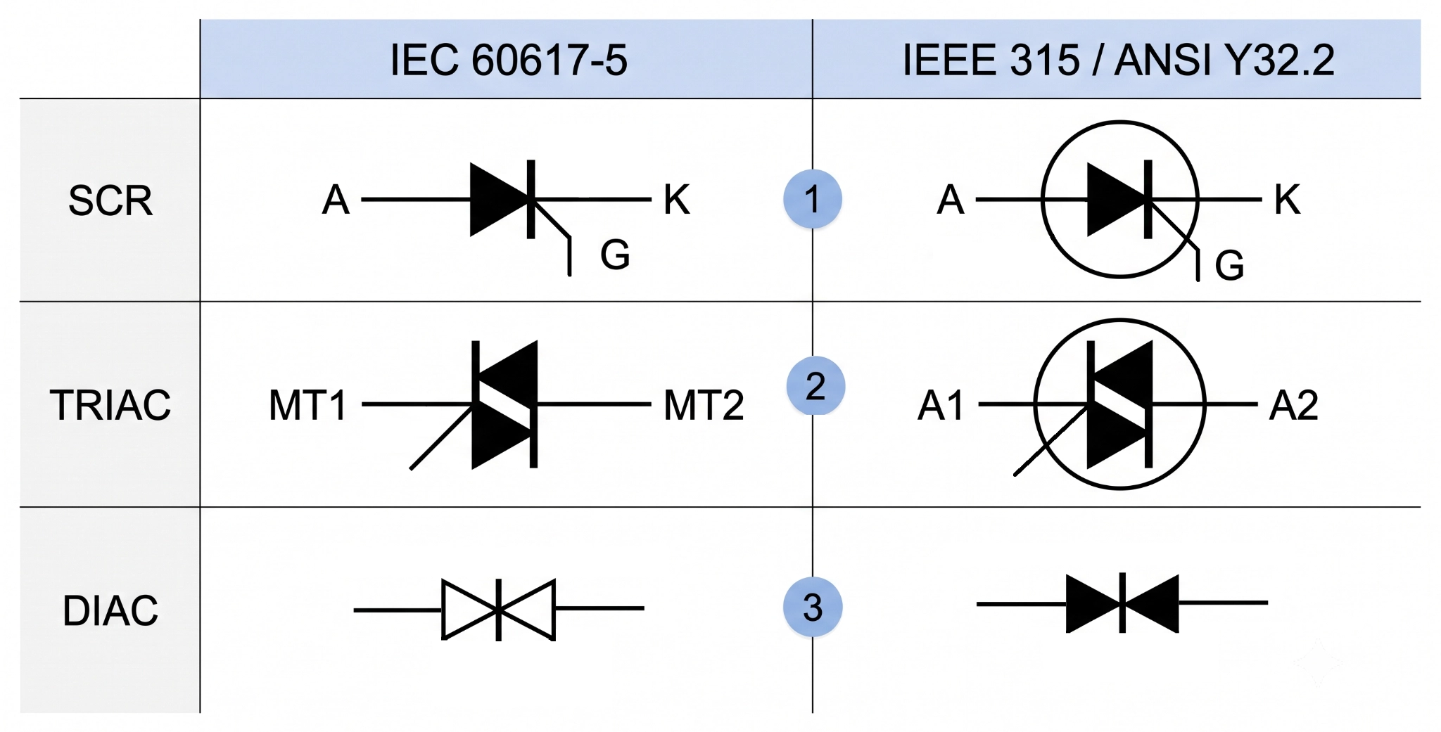
Figure: IEC and ANSI representation of the SCR, TRIAC, and DIAC symbols
- Gate geometry: IEC and ANSI/IEEE may draw the gate connection differently. The gate may leave the thyristor body at an angle in one convention and appear more horizontal in another. The geometry changes, but the gate terminal and its electrical function remain the same.
- The envelope circle: Some ANSI/IEEE-style schematics use a circle around a discrete semiconductor to indicate the device package or enclosure, while IEC symbols generally omit it. The circle is a graphical convention, not part of the device's electrical behavior.
- Terminal labels: Terminal designations can vary by device type, manufacturer, and drawing convention. For example, TRIACs may use MT1/MT2 or A1/A2 for the two main terminals. Follow the terminal labels and the manufacturer's datasheet when identifying a device.
Note: Some datasheets freely mix the two, often in a single document.
How to Identify Thyristor Terminals From a Symbol
The key distinction is simple: The symbol identifies the electrical terminals, while the device package and datasheet define their physical pinout.
They are related, but they are not interchangeable. Confusing the two is one of the easiest ways to make a wiring mistake.
Steps:
- Find the cathode bar: On an SCR symbol, the bar marks the cathode (K). The opposite terminal is the anode (A).
- Find the gate: The third terminal is the gate (G), normally drawn on the cathode side of a conventional SCR symbol.
- Check for a second device structure: A mirrored or bidirectional symbol may indicate a TRIAC or another thyristor variant, where the main terminals are not simply anode and cathode.
- Open the datasheet pinout: Never assume the physical pin order from the schematic symbol. Verify the manufacturer's pin-assignment table.
- Check the package tab: For many TO-220 devices, the metal tab is electrically connected to one of the device terminals. Do not assume it is isolated.
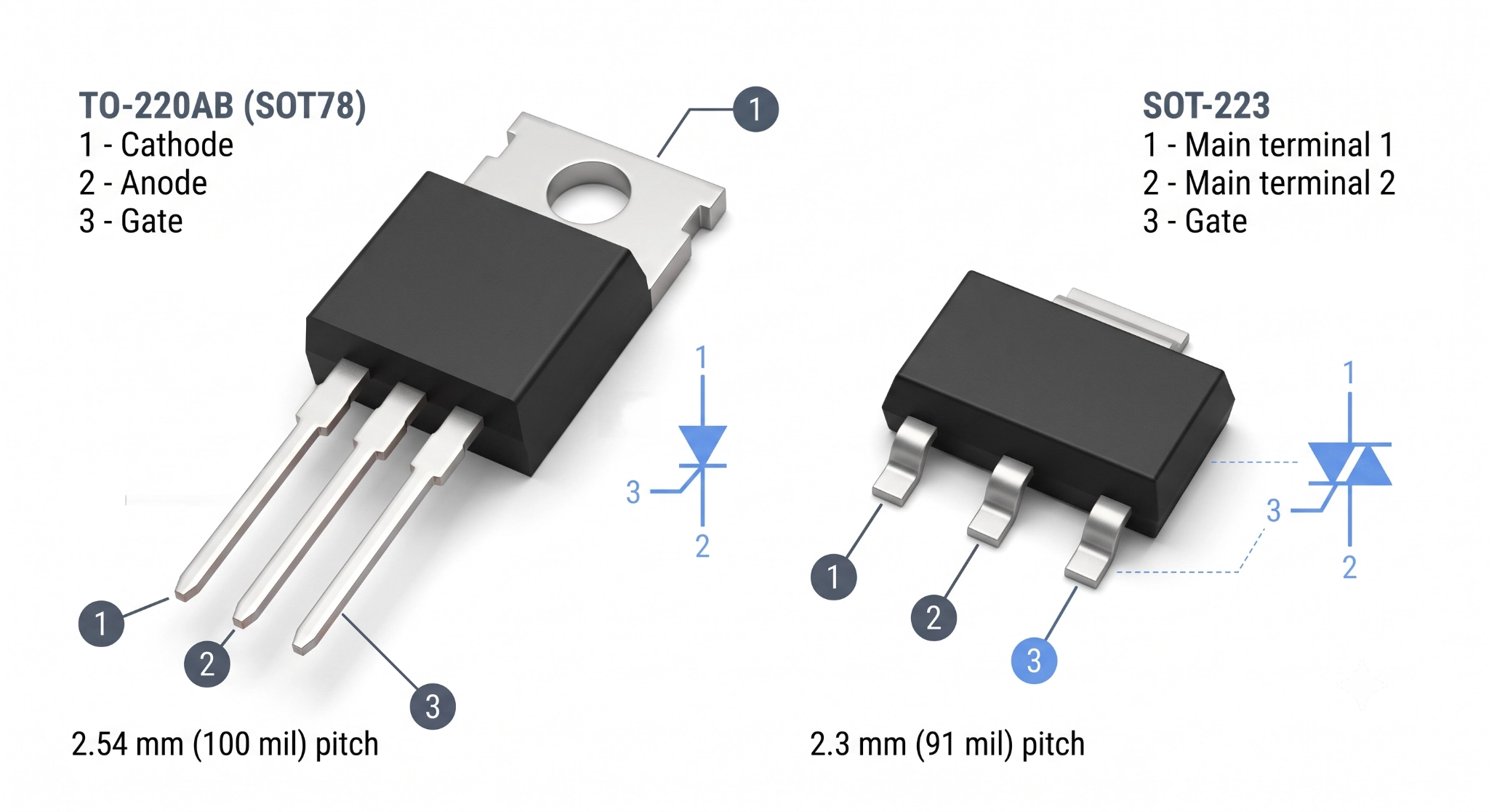
Figure: TO-220 and TO-92 thyristor packages showing physical PINs alongside their corresponding electrical terminals.
Verified examples:
- BT151, TO-220: Pin 1 = Cathode, Pin 2 = Anode, Pin 3 = Gate; the tab is connected to the anode.
- BT136, TO-220: Pin 1 = MT1, Pin 2 = MT2, Pin 3 = Gate; the tab is connected to MT2.
- BT169D, TO-92: Pin 1 = Anode, Pin 2 = Gate, Pin 3 = Cathode; no metal mounting tab.
How to Identify Thyristor Terminals From the Package
A diode-mode multimeter test can help verify the expected behavior between an SCR's gate and cathode.
However, a more precise approach is suggested because the 0.5–0.8 V reading is not a universal SCR test, and the internal gate-cathode resistor varies by device.
Step 1: Set the multimeter to diode-test mode, not continuity mode, and test the SCR out of circuit.
Step 2: Identify the suspected gate (G) and cathode (K) terminals from the datasheet. Place the red probe on G and the black probe on K.
Step 3: A forward-biased gate-to-cathode junction may show a diode-like voltage, typically around 0.5–0.8 V for many small SCRs. The exact reading depends on the device. Check the other terminal combinations for unexpected shorts.
Step 4: Reverse the probes between G and K. A conventional SCR should normally show a much higher resistance/open-circuit reading in this direction.
Important
Some larger SCRs include a gate-to-cathode resistor, so the G–K measurement can show relatively low resistance in both directions. That reading alone does not prove the device is faulty. For a definitive test, compare the measured values with the manufacturer's datasheet or test the SCR under controlled triggering conditions.
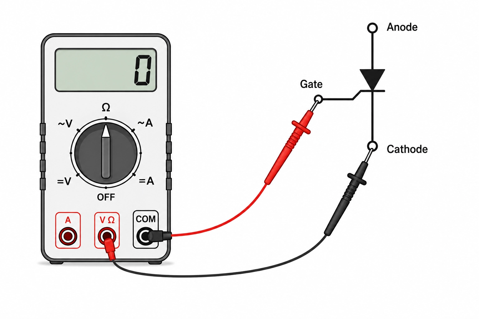
Figure: A multimeter in diode mode with the red probe on the gate and the black probe on the cathode of an SCR.
Conclusion
Read a thyristor symbol in two passes: count the bodies to understand the current path, then count the terminals to understand the control method. Once you have identified the device, stop relying on the symbol and open the datasheet pinout. The symbol tells you the electrical function, but it does not guarantee the physical pin order.
Before sending the design to fabrication, check the footprint and layout as carefully as the schematic:
- Treat the tab as an electrical connection: On many power thyristors, the metal tab is internally connected to a device terminal. If it carries mains potential, give it the same clearance and creepage consideration as any other high-voltage conductor.
- Verify creepage and clearance: Do not rely on a single generic spacing value for every design. The required distance depends on working voltage, pollution degree, insulation type, material group, altitude, and the applicable safety standard. Use the relevant IPC and product safety requirements for the specific application.
FAQs About the Thyristor Symbol
Q: What Does the Thyristor Symbol Mean?
It marks a four-layer PNPN switch that conducts in one direction and latches. The diode-shaped body shows the conduction direction, and the extra gate leg shows that the device must be triggered before it conducts at all.
Q: Is the SCR Symbol the Same as the Thyristor Symbol?
In everyday use, yes. The SCR is the original and most common thyristor, so its symbol became the default picture for the whole family. Strictly, thyristor covers fifteen or more symbols, and the SCR is one member.
Q: How Do You Tell an SCR Symbol From a TRIAC Symbol?
Count the diode bodies. An SCR has one body pointing one way, with terminals marked A and K. A TRIAC has two mirrored bodies sharing one gate, and its terminals are MT1 and MT2 because neither is permanently the anode.
Q: Why Does the DIAC Symbol Have No Gate?
Because a DIAC has no gate terminal to draw, it conducts only when the voltage across it exceeds its breakover value in either direction, typically 32 V on a DB3. The missing leg indicates the trigger point is fixed within the silicone.
Q: What Do A, K, and G Mean on a Thyristor Symbol?
A is the anode, K the cathode, and G the gate. Cathode uses K rather than C because the collector already takes C on transistor symbols. Bidirectional devices replace A and K with MT1 and MT2.
Popular Articles
• Logic Gate Symbols: The Complete Chart, Truth Tables [2026]
• How to Design and Assemble a Reliable ESP32 Module PCB on a 2-Layer Board
• How to Identify SMD LED Polarity: Markings, Testing, and PCB Tips
• The Ultimate Guide to Relay Symbol: Coil, Contacts, Diagrams, and Circuit Applications
• Power Supply Symbols Chart: A Complete Guide to AC, DC, Ground, Battery, and Source Symbols
Keep Learning
How to Read Resistor Color Code: Complete Guide with Chart and Examples
4-Band Resistor Color Code Explained A 4-band resistor color code is one of the most common methods used to indicate resistance values in electronic components. It is widely used to help engineers and hobbyists quickly determine resistance values without using a resistor color code calculator. In a standard 4-band resistor: First Band (Digit 1): Represents the first significant digit Second Band (Digit 2): Represents the second significant digit Third Band (Multiplier): Indicates the factor by which t......
Solder Paste vs Flux: What's the Difference and When Should You Use Each?
Solder paste and flux are not interchangeable. Solder paste contains solder alloy powder and flux, while flux contains no solder alloy. This difference matters when choosing materials for SMT, reflow soldering, or manual soldering. Flux removes metal oxides and prevents re-oxidation, allowing molten solder to wet copper pads and component leads properly. Solder paste combines flux with fine solder alloy powder. During reflow, the flux activates to improve wetting while the solder alloy melts to form t......
Fiducial Marks in PCB and SMT Assembly: A Complete Guide to Accuracy and Design Rules
Modern Printed Circuit Boards (PCBs) are complex, integrating high-density components like 0.4mm pitch Ball Grid Arrays (BGAs), 0201 passives, and fine-pitch Quad Flat No-Lead (QFN) packages. In this advanced manufacturing environment, achieving placement accuracy measured in micrometers is crucial. A significant challenge in automated manufacturing is how pick-and-place machines, which handle thousands of components per hour, precisely locate the PCB. A board on a conveyor system is never in the perf......
Ground Symbols Explained: Earth, Chassis, Signal, Analog, Digital Ground & More
Key Takeaways ⬇ Download the Ground Symbol Cheat Sheet (PDF) Keep all six ground symbols and their standard numbers on one page for quick reference. Four IEC 60417 symbols: IEC 60417 defines symbol 5017 for earth, 5018 for functional earth, 5019 for protective earth, and 5020 for frame/chassis. Protective earth is safety-related: IEC 60417-5019 identifies the protective earth connection and is used for safety-related protective bonding. Signal ground uses a different convention: IEEE Std 315 defines t......
How to Choose an ESP32 Development Board: A Beginner-Friendly Guide
The leap from blinking a simple LED to building a cloud-connected smart home device is a thrilling milestone for any electronics beginner. At the heart of this transition is often one undisputed champion: the ESP32. However, when you first search for an ESP32 development board, you are instantly met with a dizzying array of models, shapes, and specifications. How do you know which one is right for your first IoT (Internet of Things) project? In this beginner's guide, we will break down what makes thes......
How to Design an ESP32-S3 Development Board from Scratch: A 4-Layer PCB Design Tutorial
Designing your own ESP32-S3 development board gives you complete control over your hardware architecture while preparing your IoT projects for commercial production. Instead of relying on bulkier, off-the-shelf boards, building a custom design allows you to optimize the board space, expose only the required GPIO pins, and integrate peripherals directly onto a single substrate. In this tutorial, we will design a 4-layer ESP32-S3 development board from scratch. We will walk through the entire hardware d......