SMD Inductor Code: How to Read Inductor Markings and Values
17 min
- SMD Inductor Code Chart
- Why Most SMD Inductors Have No Marking
- How to Read SMD Inductor Codes
- What an SMD Inductor Marking Doesn't Tell You
- Inductor Polarity: What the Dot Means
- How to Identify an Unmarked SMD Inductor
- SMD Inductor Identification Checklist
- Specify Inductors by Part Number, Not by Marking
- FAQ about SMD Inductor Codes
Key Takeaways
Three digits are read in µH: 100 is 10 µH and 101 is 100 µH. The third digit is the number of zeros, not part of the value.
R and N are decimal points: R in microhenries (4R7 = 4.7 µH), N in nanohenries (2N2 = 2.2 nH).
A trailing letter is a tolerance: K is ±10% and M is ±20%. On RF inductors below about 10 nH, C and D mean ±0.2 nH and ±0.5 nH.
Most small chip inductors are unmarked: identify them from the BOM or reel label first, then with an LCR meter at the right test frequency.
The marking is only the nominal value: the five 10 µH parts in this article are rated from 15 mA to 5.5 A, so match Isat, rated current and DCR, not just the code.
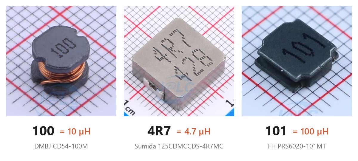
Figure: Three power inductors from the JLCPCB parts library. 100 is 10 µH, 4R7 is 4.7 µH and 101 is 100 µH. The 128 under the Sumida part's 4R7 is not part of the value.
An SMD inductor marked 100 is 10 µH, not 100 µH. The code reads like a 3-digit resistor code with microhenries in place of ohms, and that one rule decodes most of the markings printed on power inductors.
The rule doesn't cover everything. Most small chip inductors carry no marking at all, RF inductors are coded in nanohenries, and the letter after the digits is usually a tolerance that looks like a unit. This guide works through each case with real parts from the JLCPCB parts library, then covers what a marking can't tell you and how to identify an inductor that has none.
SMD Inductor Code Chart
Common codes on SMD power inductors, read in microhenries:
| Code | Inductance | How to read it |
|---|---|---|
| 100 | 10 µH | 10 × 10⁰. The last digit is the number of zeros |
| 101 | 100 µH | 10 × 10¹ |
| 220 | 22 µH | 22 × 10⁰ |
| 221 | 220 µH | 22 × 10¹ |
| 470 | 47 µH | 47 × 10⁰ |
| 4R7 | 4.7 µH | R is the decimal point |
| R47 | 0.47 µH | A leading R means below 1 µH |
| 100K | 10 µH ±10% | K is tolerance, not kilo |
| 100M | 10 µH ±20% | M is tolerance, not milli |
RF chip inductors are coded in nanohenries (2N2, 13N), covered below. Check which family a part belongs to before you apply this table.
Why Most SMD Inductors Have No Marking
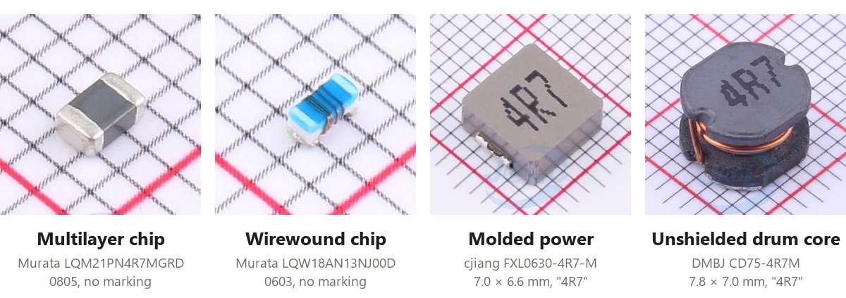
Figure: The two chip inductors on the left have no marking. The molded and drum-core power inductors on the right are both printed 4R7, or 4.7 µH.
Small chip inductors are usually blank. Murata's specification for its LQW18AN wirewound series simply says "No marking", and Coilcraft states that its 0201, 0302, 0402, 0403 and some 0603 RF inductors are not marked because of their size. The identification goes on the reel instead: Murata's reel label carries the customer part number, the Murata part number, an inspection number and the quantity.
Resistors have the same size problem, but once there is room to print, chip resistors share a few common systems, covered in our guide to SMD resistor codes. Chip inductors never settled on one. Multilayer ceramic capacitors are mostly unmarked too, as our SMD capacitor code guide explains.
Printed codes are mainly found on the larger power inductors: drum-core, shielded and molded parts with enough top surface for three characters. A blank 0402 or 0603 inductor pulled off a board is normal, and our SMD inductor size guide lists the common package dimensions if you need to work out what you are holding.
How to Read SMD Inductor Codes
Inductor codes appear in two places: printed on the body of larger power inductors, and inside the manufacturer part number of most inductors, marked or not. The same rules decode both. SDFL2012S100KTF is a blank 0805 chip, but its part number still carries 100 (10 µH) and K (±10%).
The 3-Digit Code: 100, 101, 220, 470
The first two digits are significant figures and the third is the number of zeros, with the result in microhenries:
- 100 = 10 × 10⁰ = 10 µH
- 101 = 10 × 10¹ = 100 µH
- 220 = 22 µH, and 221 = 220 µH
- 470 = 47 µH, and 471 = 470 µH
Changjiang Microelectronics (cjiang) gives the same examples in its FXL molded inductor datasheet: 1R0 is 1.0 µH, 100 is 10 µH and 101 is 100 µH. Reading 100 as 100 µH is a factor-of-ten mistake. In a buck converter, where ripple current scales with 1/L, the wrong part changes the ripple current by that same factor.
R as the Decimal Point: 4R7, 1R0, R47
R stands in for the decimal point in microhenries, the same way it does in ohms on a resistor. 4R7 is 4.7 µH, 1R0 is 1.0 µH and R47 is 0.47 µH. Every 4.7 µH molded or drum-core inductor in this article is printed 4R7.
N as the Decimal Point in Nanohenries: 2N2, 13N
RF inductors use N the same way, for nanohenries. In Murata's LQW18AN series, 2N2 is 2.2 nH and 13N is 13 nH. Once the value reaches 100 nH, the same series switches to R: LQW18ANR10J00D is 0.10 µH, or 100 nH. One product family uses both letters, and R still means microhenries.
Mixing up the two is a 1000× error, since 4R7 is 4.7 µH and 4N7 is 4.7 nH. N is a manufacturer convention rather than a standard. Outside RF inductors it can mean something else, such as the ±30% tolerance on FH power inductors, so check the product family before decoding it.
Tolerance Letters: J, K, M and Others
A letter after the value is normally the tolerance. 100K is 10 µH ±10%, and 100M is 10 µH ±20%. M causes the most trouble, because 100M looks like 100 mH, a reading 10,000 times too high.
| Letter | Tolerance | Example part |
|---|---|---|
| C | ±0.2 nH | Murata LQW18AN3N6C00D (3.6 nH) |
| D | ±0.5 nH | Murata LQW18AN2N2D00D (2.2 nH) |
| G | ±2% | Murata LQW18AN13NG00D (13 nH) |
| J | ±5% | Murata LQW18AN13NJ00D (13 nH) |
| K | ±10% | Sunlord SDFL2012S100KTF (10 µH) |
| M | ±20% | DMBJ CD54-100M (10 µH) |
| N | ±30% | FH PRS6020-1R5NT (1.5 µH) |
C and D are absolute tolerances, used on RF inductors below about 10 nH. LQW18AN2N2D00D is 2.2 nH ±0.5 nH, or about ±23%. Read D as ±0.5% and you are off by a factor of 45.
The letters aren't fully standardized either. FH uses N for ±30%, while Bourns ends its ±30% SRR6028 part numbers in Y. If a suffix isn't in the table, look it up in that manufacturer's part-numbering section instead of guessing.
Second Lines and Other Extra Characters
Many power inductors print a second line under the value: 128 on the Sumida 125CDMCCDS-4R7MC at the top of this article, M57 on the Sumida CDRH74NP-100MC further down. Neither is part of the inductance. Decode only the code you can match to the part number in the datasheet. The other characters are typically lot or date codes, in a format that varies by manufacturer.
A marking that fits none of the formats above, such as two letters or a logo followed by digits, is probably an abbreviated part number. Short SMD transistor codes have the same problem, and the fix is the same: identify the manufacturer from the logo, then look the code up in its marking table.
Inductor Color Codes and Color Dots
Through-hole axial inductors use color bands read like resistor bands, in microhenries. The first two bands are digits, the third is the multiplier and the fourth is the tolerance. The digit colors are black 0, brown 1, red 2, orange 3, yellow 4, green 5, blue 6, violet 7, gray 8 and white 9, so brown-black-black is 10 µH. A gold multiplier means ×0.1 and silver ×0.01, so red-red-gold is 2.2 µH. In the tolerance position, gold is ±5%, silver ±10% and black ±20%. A gold band in the first or second position is a decimal point.
Coilcraft uses color dots on many of its SMD RF inductors. Its 0603 (except 0603CT), 0805 (except 0805HP) and some 1008 parts carry a single dot whose value is listed on each series' data page. Other 1008, 1206 and 1812 parts carry three dots: the first two are digits and the third is the multiplier, in nanohenries, so gray-red-black is 82 nH and brown-red-brown is 120 nH. Below 10 nH the third dot is not a multiplier, and the value comes from a table on Coilcraft's RF inductor color coding page. Coilcraft also states that the dots do not indicate polarity.
What an SMD Inductor Marking Doesn't Tell You
A marking gives the nominal inductance and sometimes the tolerance. It doesn't give the current rating, the saturation current (Isat) or the DC resistance (DCR), and those decide whether a part survives in the circuit.
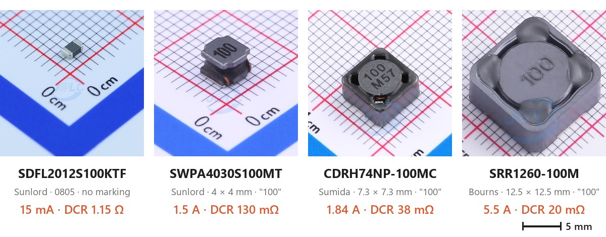
Figure: Four 10 µH inductors at roughly the same scale, labeled with the current rating and DCR from the JLCPCB parts library.
All four parts above are 10 µH, and three are printed with the same 100. Add the CD54-100M from the first photo and you have five parts with one nominal value:
| Part | Size | Marking | Current rating | DCR |
|---|---|---|---|---|
| Sunlord SDFL2012S100KTF | 2.0 × 1.25 mm (0805) | None | 15 mA | 1.15 Ω |
| DMBJ CD54-100M | 5.8 × 5.2 mm | 100 | 1.44 A | 100 mΩ |
| Sunlord SWPA4030S100MT | 4 × 4 mm | 100 | 1.5 A | 130 mΩ |
| Sumida CDRH74NP-100MC | 7.3 × 7.3 mm | 100 | 1.84 A | 38 mΩ |
| Bourns SRR1260-100M | 12.5 × 12.5 mm | 100 | 5.5 A | 20 mΩ |
Drop the 0805 part into a 1 A buck converter because the value matches, and it carries 67 times its rated current while dissipating about 1.15 W in its DCR. The 4R7 parts in this article show the same spread at 4.7 µH: the DMBJ CD75-4R7M is rated 3.2 A with 58 mΩ DCR, the cjiang FXL0630-4R7-M 6 A with 33 mΩ, and the Sumida 125CDMCCDS-4R7MC 14 A with 10 mΩ.
Isat itself isn't defined the same way everywhere. Sumida's CDMC datasheet defines it as the DC current at which inductance falls 30% below its initial value, while Bourns specifies a 25% drop for the SRR1260, so Isat figures from two datasheets are not always comparable. Our SMD inductor selection guide covers how to choose between parts.
Treat a decoded marking as the nominal inductance and nothing more. To replace a part, match the full manufacturer part number, or at minimum the inductance, Isat, rated current, DCR and footprint.
Inductor Polarity: What the Dot Means
Inductors have no electrical polarity. Reversing one doesn't change its inductance or how it works in the circuit. Some power inductors still carry a dot, and its meaning depends on the manufacturer.
Where the datasheet defines it, the dot marks the start of the winding, and in a switching regulator the orientation can affect EMI. Analog Devices measured inductor orientation and emissions on several parts. Flipping a Coilcraft XAL6060 changed AM-band emissions by 17 to 20 dBµV/m. On Würth's WE-XHMI series, whose top marking shows the winding start, the lowest emissions came with the winding start on the switch (SW) node. On the WE-MAPI series, every part has a dot, but the datasheet does not define it as the start of the winding.
If the datasheet defines the dot, put it on the SW node, add a pin-1 mark to the footprint's silkscreen, and check the orientation in the component placement preview when you order assembly. If the datasheet doesn't define it, the dot tells you nothing about the winding, and for an EMI-critical design ADI's advice is to measure emissions in both orientations. The rest of the switch-node layout is covered in our guide to PCB layouts for switching regulators.
How to Identify an Unmarked SMD Inductor
For a blank part, documentation beats measurement, so start there.
Check the BOM, Reel Label or Order Record
The reel label gives the full manufacturer part number, which no measurement can recover. On an assembled board, the BOM lists each part by reference designator and part number. For a board assembled by JLCPCB, search the C-number from the BOM in the JLCPCB parts library to get the exact part and its datasheet.
Look at Where the Part Sits
A blank black chip in series with a supply pin, next to decoupling capacitors, is as likely to be a ferrite bead as an inductor, and the two often look identical. The part between a converter's SW pin and its output capacitors is the power inductor. A blank chip in an antenna matching network can be a capacitor, a 0 Ω jumper or a nanohenry RF inductor.
Measure It with an LCR Meter
An LCR meter reads inductance directly, but the test frequency matters. At 100 Hz, a 10 µH inductor has 6.3 mΩ of reactance, a small fraction of the CD54-100M's 100 mΩ DCR, and the inductance reading becomes unreliable. At 100 kHz the reactance is 6.3 Ω and the reading is solid. Where you can, measure at the datasheet's test frequency. The power inductors in this article are specified at 100 kHz (FXL0630, PRS6020, Sumida CDMC) or at 1 kHz (CD54-100M, SRR1260-100M).
Nanohenry RF inductors are out of reach for most benchtop meters. Murata specifies the LQW18AN at 100 MHz. At 100 kHz, 13 nH is only about 8 mΩ of reactance, and a few centimeters of test lead can add more inductance than the part itself. Telling 10 nH from 15 nH takes an impedance analyzer or a VNA with a suitable fixture.
The meter also measures with a small AC signal and no DC current, so the reading says nothing about Isat. A part that reads 10 µH on the bench can still saturate at a few hundred milliamps.
Use a Multimeter Only to Rule Things Out
A multimeter confirms there is a low-resistance DC path. Expect anything from tens of milliohms to an ohm or two: 100 mΩ on the CD54-100M, 1.15 Ω on the SDFL2012S100KTF and 1.2 Ω on the 100 µH PRS6020-101MT. The lower values are below what most handheld meters can resolve once lead resistance is included.
A low reading rules out a capacitor, an open part and a high-value resistor. It can't separate an inductor from a ferrite bead, a 0 Ω jumper or a low-value resistor, since all of them read close to zero.
SMD Inductor Identification Checklist
- Look for a marking. If there is none, go to step 6.
- Three digits: the first two are the value and the third is the number of zeros, in µH. 100 is 10 µH.
- R or N in the code: R is the decimal point in µH, N in nH.
- A letter after the value: read it as a tolerance (J, K, M), not as a unit. On RF parts below about 10 nH, C and D mean ±0.2 nH and ±0.5 nH.
- Check that the result fits the package and the circuit. A 100 µH, 3 A inductor will not fit in an 0402. If the value doesn't fit, recheck the unit, or treat the marking as a lot code.
- Find the part number on the BOM, the reel label or the order record.
- With no documentation, check where the part sits in the circuit, then measure it with an LCR meter at a suitable test frequency.
- Before replacing it, match Isat, rated current, DCR and footprint, not only the inductance.
Specify Inductors by Part Number, Not by Marking
For a repair, a decoded marking is a starting point for finding a replacement. For a production BOM it isn't enough. The marking leaves out the current rating and DCR, and the current rating alone varied by more than 300× across the 10 µH table above. List every inductor by its full manufacturer part number.
In the JLCPCB parts library, each inductor's page lists the inductance, tolerance, current rating, DCR and, for many parts, Isat, together with the datasheet. The Basic library includes 10 µH multilayer chips such as SDFL1608S100KTF (C1035, 0603) and SDFL2012S100KTF (C1046, 0805), and on Economic PCBA Basic parts carry no feeder loading fee.
Those two are rated 3 mA and 15 mA, which suits filtering a low-current analog or reference rail, not a converter's power stage. For a power stage, choose from the power inductor category by Isat and DCR. When the BOM is ready, upload it with your Gerber and CPL files to get an instant PCBA quote.
FAQ about SMD Inductor Codes
Q: What does 100 mean on an SMD inductor?
10 µH. The first two digits are the value and the third is the number of zeros, so 100 is 10 × 10⁰ µH. On RF parts coded in nanohenries, 10 nH is usually written 10N.
Q: What does 4R7 mean on an inductor?
4.7 µH. R marks the decimal point in microhenries, so 1R0 is 1.0 µH and R47 is 0.47 µH. With an N instead, 4N7 would be 4.7 nH.
Q: What does 101 mean on an inductor?
100 µH: 10 followed by one zero, in microhenries. The FH PRS6020-101MT in the first photo is a 100 µH part marked this way.
Q: What do K and M mean after an inductor code?
Tolerance. K is ±10% and M is ±20%, so 100K is 10 µH ±10%. Neither is a unit, and 100M is not 100 mH.
Q: Do SMD inductors have polarity?
No. An inductor works the same in either direction. Where a power inductor's datasheet defines its dot, the dot marks the start of the winding, and putting that end on the switch node can lower EMI in a switching regulator. Coilcraft's color dots on RF chip inductors mark the value and do not indicate polarity.
Q: Why do some SMD inductors have no marking?
Chip inductors of roughly 0603 and smaller have no room for a legible code, and manufacturers such as Murata and Coilcraft leave most of them blank. The part number is on the reel label and in the BOM instead.
Q: Can a multimeter identify an unmarked inductor?
Only partly. It shows a low-resistance DC path, which rules out capacitors and open parts, but a ferrite bead, a 0 Ω jumper and an inductor all read close to zero. Measuring the inductance takes an LCR meter, and nanohenry RF parts need an impedance analyzer or a VNA.
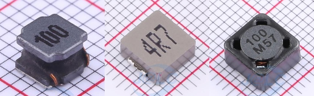
Each part page lists the manufacturer part number, key parameters and datasheet
Basic parts carry no feeder loading fee on Economic PCBA
Upload your BOM and CPL for an instant PCBA quote
Popular Articles
• SMD Resistor Package Sizes: Complete Size Chart, Footprints & How to Choose
• How to Solder SMD Components Like a Pro [2026 Updated]
• SMD Resistor Codes: How to Read 3-Digit, 4-Digit, and EIA-96 Markings
• SMD Capacitor Codes: Identification, Markings, and Polarity
• SMD Capacitor Sizes: Complete Size Chart and Selection Tips for PCB Design and Assembly
Keep Learning
SMD Inductor Code: How to Read Inductor Markings and Values
Key Takeaways Three digits are read in µH: 100 is 10 µH and 101 is 100 µH. The third digit is the number of zeros, not part of the value. R and N are decimal points: R in microhenries (4R7 = 4.7 µH), N in nanohenries (2N2 = 2.2 nH). A trailing letter is a tolerance: K is ±10% and M is ±20%. On RF inductors below about 10 nH, C and D mean ±0.2 nH and ±0.5 nH. Most small chip inductors are unmarked: identify them from the BOM or reel label first, then with an LCR meter at the right test frequency. The m......
A Complete Guide to Surface Mount Device (SMD)
Imagine holding a smartphone in your hand. Inside that sleek device lies a complex network of thousands of miniature components — resistors smaller than a grain of rice, capacitors thinner than a fingernail, and integrated circuits containing millions of transistors. Without Surface Mount Technology (SMT) and its compact Surface Mount Devices (SMDs), none of this would exist. Just a few decades ago, electronics were bulky. Radios filled desks, computers filled rooms, and assembling a circuit meant dri......
TSSOP Package Guide: Dimensions, Pitch, Footprint & SMT Soldering
Key Takeaways Lead span, not body width: Build the footprint from the lead span (6.4 mm or 8.1 mm tip to tip), not the 4.4 mm or 6.1 mm body width. MSOP vs TSSOP: Check the width in the drawing before reusing a footprint: MSOP-8 and TSSOP-8 share pitch and body length, and some vendors label a 3.0 mm-wide package TSSOP8. Mask dams: A standard TSSOP footprint leaves a 0.20 mm pad gap: enough for solder mask dams on 1 oz copper, no margin on 2 oz, and no dams on JLCPCB flex boards. Thermal pad: On HTSSO......
Understanding the Role of PCB Controllers in Electronic Design
A PCB Controller is an important part of designing and building electrical systems. It controls the functions of different mechanical parts on a printed circuit board (PCB) and makes sure they can talk to each other easily. People use PCB controllers in a lot of different situations, from home technology to factory automation. The purpose of this article is to discuss the importance of PCB controllers, including the different kinds, their uses, and the best ways to choose and use them. 1. What is a PC......
How Nixie Tubes Work: The Glow Behind the Glass
Let me take you in the past, when there were no LED or LCD lights for display, rather a technology that consumes a lot of power but looks awesome. Nixie tubes, a softly glowing orange digits inside a glass tube. But nowadays these have just become obsolete, for some electronics hobbyists still keep them alive as a vintage piece from history. In this article, we’ll dive into how Nixie tubes work. Moreover, we will know the technology behind them and the history that brought them from laboratory equipme......
GaN vs Silicon: Which Power Device Should You Use
Have you heard something about GaN? It is quite popular nowadays. Not because it is a different technology that saves power, but because today electronics are moving towards miniaturization. And we need small power supplies that can handle a lot more current and power and dissipate less heat. This is all possible due to GaN MOSFETs available in SMT packages out there. There are a lot of new companies that took this idea and implemented it into small mobile and laptop chargers, and generated a lot of r......