
Complete SMD Inductor Size Guide: Dimensions, Packages, and PCB Design Tips
15 min
- What Does SMD Inductor Size Mean?
- SMD Inductor Size Chart
- Standard RF Chip Inductor Package Sizes
- Standard Power Inductor Package Sizes
- High-Current Shielded SMD Power Inductor Sizes
- How to Select the Right SMD Inductor Size
- How SMD Inductor Size Affects Electrical Performance
- PCB Footprint and Layout Considerations for SMD Inductors
- Common SMD Inductor Types
- FAQs about SMD Inductor Size
- Conclusion
SMD inductor size affects far more than PCB real estate. Package dimensions directly influence current handling, saturation behavior, DCR, and EMI characteristics. Picking the wrong package can mean a costly board respin, not just inefficiency.
One challenge is that SMD inductor package sizes use multiple naming conventions and the fundamental split between RF chip inductors (compact footprint, high Q-factor) and power inductors (low DCR, magnetic shielding, high saturation current).
This guide covers package size charts, RF vs power inductor types, high-current packages, footprint considerations, and selection criteria for each application category.
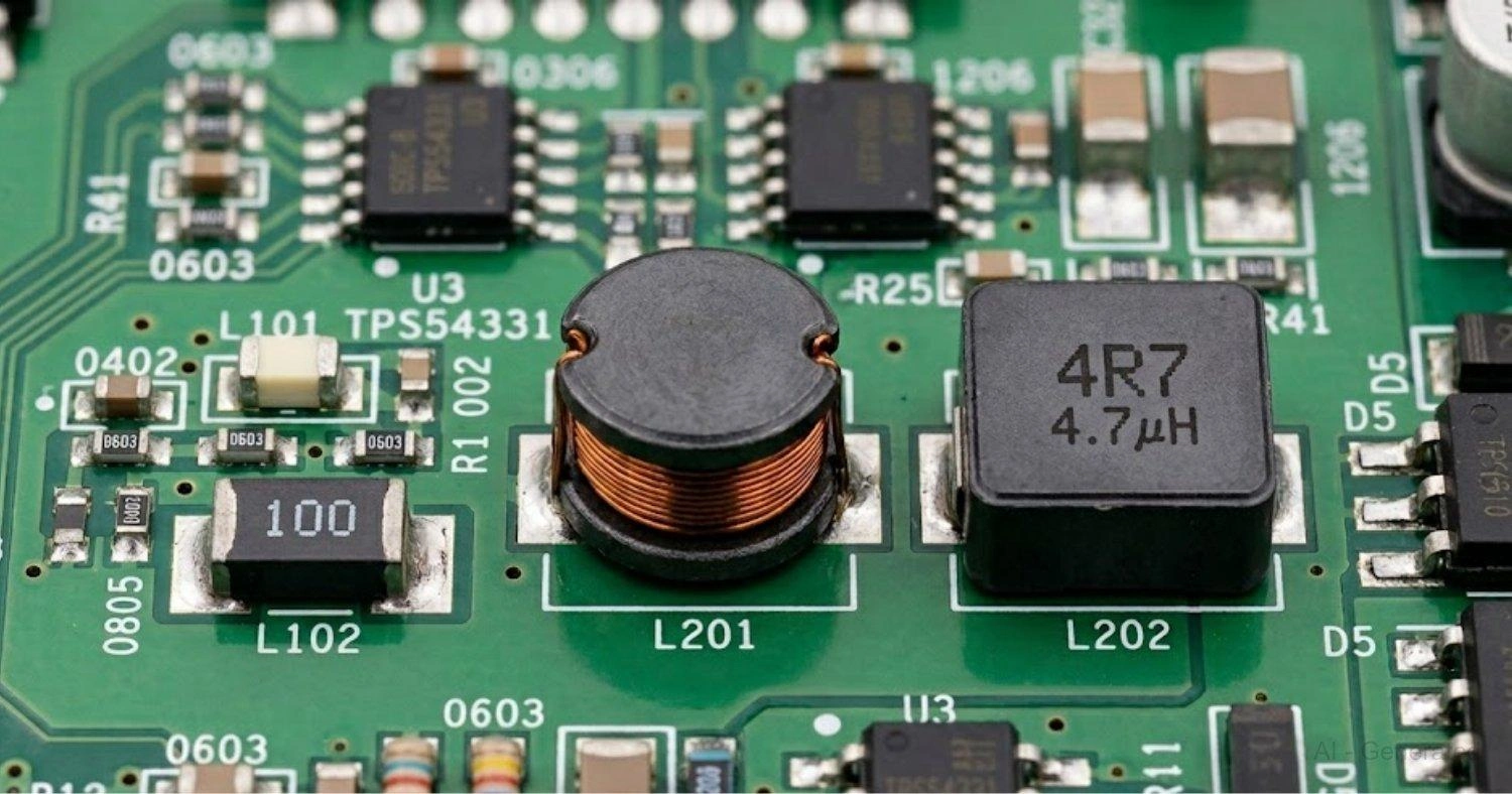
Figure: Populated PCB showing four SMD inductor types: 0402 chip, 0805 chip, CD drum-core, and NR shielded power inductor.
Note
If you're new to inductor fundamentals, see our complete guide to SMD inductors.
What Does SMD Inductor Size Mean?
SMD inductor size refers to the physical footprint of the component, specifically its length and width on the PCB. Like resistors and capacitors, inductors follow a standardized 4-digit naming system where the digits encode dimensions.
Imperial vs Metric Package Naming
Imperial (e.g., 0805): First two digits = length in hundredths of an inch; last two = width
Metric (e.g., 2012): Digits directly represent dimensions in tenths of a millimeter Size directly affects electrical performance: smaller packages have tighter windings, which usually means higher DC resistance (DCR) and lower current ratings.
| Imperial | Metric | Dimensions (L x W) |
|---|---|---|
| 0402 | 1005 | 1.0 x 0.5 mm |
| 0603 | 1608 | 1.6 x 0.8 mm |
| 0805 | 2012 | 2.0 x 1.2 mm |
| 1206 | 3216 | 3.2 x 1.6 mm |
| 1210 | 3225 | 3.2 x 2.5 mm |
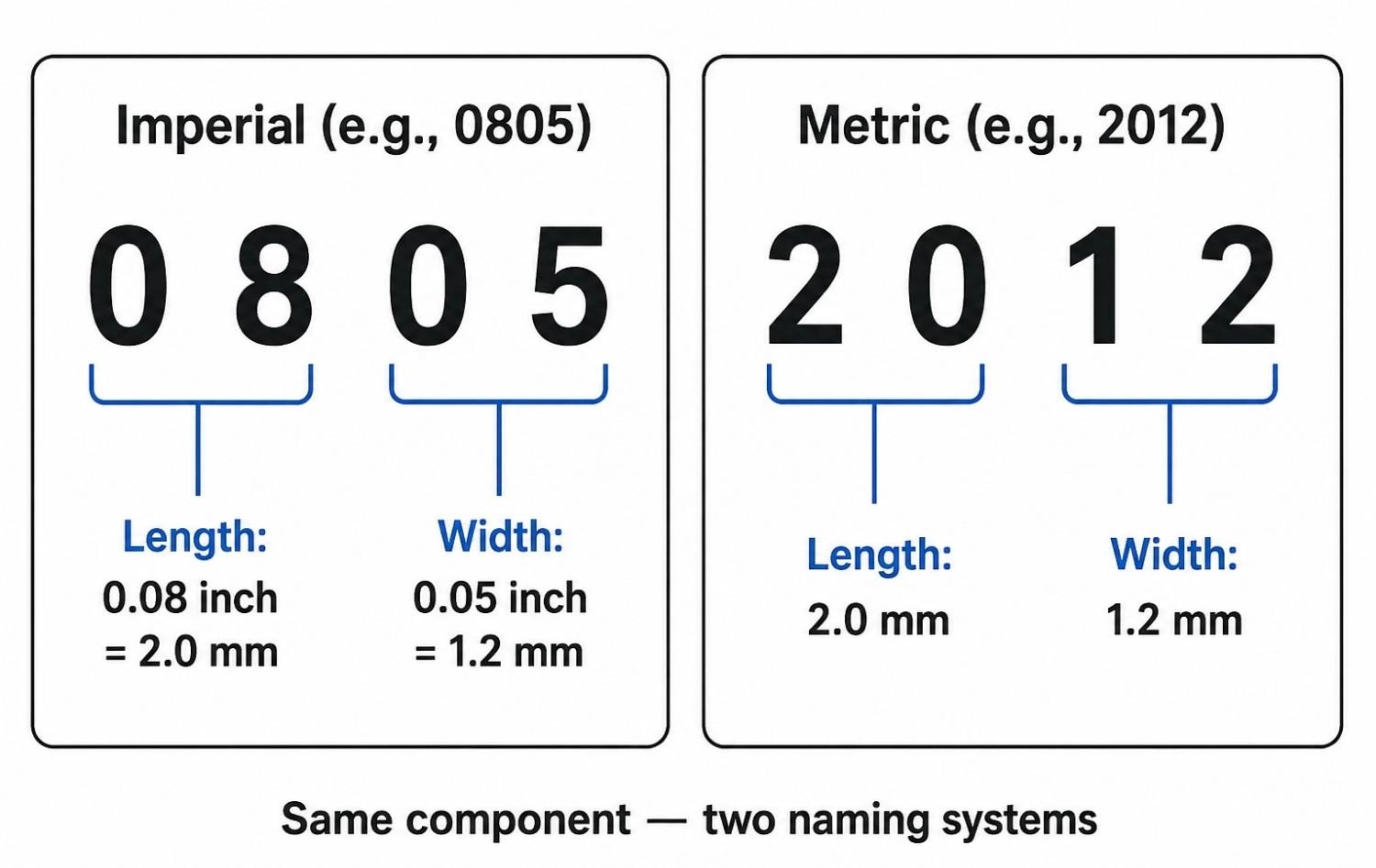
Figure: Showing how SMD package codes 0805 (imperial) and 2012 (metric) both decode to the same 2.0 x 1.2 mm dimensions.
SMD Inductor Size Chart
1. Standard Chip / RF Inductors Size Chart
| Package Code | Dimensions (mm) | Typical Use |
|---|---|---|
| 0402 / 1005 | 1.00 x 0.50 | RF circuits, compact mobile devices |
| 0603 / 1608 | 1.60 x 0.80 | General RF/signal, wearable tech |
| 0805 / 2012 | 2.00 x 1.20 | General-purpose signal, filtering |
| 1206 / 3216 | 3.20 x 1.60 | Higher current handling, simple filters |
| 1210 / 3225 | 3.20 x 2.50 | High Q-factor circuits |
2. Standard Power Inductors Size Chart
| Package Code | Dimensions (mm) | Typical Current Range |
|---|---|---|
| CD32 | dia 3.2 x H2.5 | 0.2 A - 1.5 A |
| CD43 | dia 4.3 x H3.0 | 0.5 A - 3 A |
| CD54 | dia 5.4 x H4.0 | 0.8 A - 4 A |
| CD73 | dia 7.3 x H3.0 | 1 A - 6 A |
| CD75 | dia 7.3 x H5.0 | 1 A - 8 A |
| NR3015 | 3.0 x 3.0 x 1.5 | 1 A - 3 A |
| NR6045 | 6.0 x 6.0 x 4.5 | 1.5 A - 10 A |
Note
CD series inductors are drum-core (cylindrical). Dimensions follow diameter x height convention. Exact dimensions vary by manufacturer, so always verify against the specific datasheet.
3. High Current / Shielded Power Inductors Size Chart
| Package Series | Dimensions (mm) | Performance Profile |
|---|---|---|
| 1004 / 1005 | 10 x 10 x 4-5 | Up to 15 A+ |
| 1205 / 1207 | 12 x 12 x 5-7 | Low DCR, high saturation |
| 1770 / 1707 | 17 x 17 x 7 | 20 A - 60 A support |
Standard RF Chip Inductor Package Sizes
Chip inductors are optimized for signal-path applications where physical size and Q-factor matter more than raw current capacity. They are the standard choice in RF circuits, filtering networks, and compact consumer electronics.
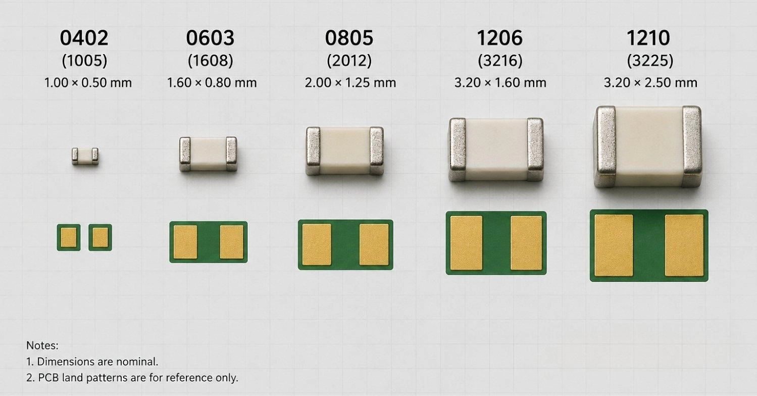
Figure: SMD chip inductor packages 0402 through 1210 drawn to relative scale, with package codes, dimensions, and PCB land patterns labeled.
Engineering Note
Smaller packages increase routing density but come with higher DCR and lower current ratings. For signal-path use that is usually acceptable; for power-path use, it is a hard constraint.
0402 and 0603 Inductors
These are the go-to for ultra-compact electronics where every square millimeter counts.
- Common in RF matching networks, antenna circuits, and impedance tuning
- Standard in smartphones, hearing aids, and wearable devices
- Higher DCR relative to size. Adequate for signal-level currents, not power stages
- Require accurate paste deposition and strict reflow soldering profiling; manual soldering is highly difficult
0805 and 1206 Inductors
These two sizes hit the practical sweet spot for most PCB designers.
- Better thermal handling compared to 0402/0603
- Easier to inspect, rework, and hand-solder during prototyping
- 1206 supports slightly higher current and lower DCR than 0805
Widely supported in automated SMT lines, including standard PCB assembly service at JLCPCB. If you are targeting manufacturability alongside reasonable current handling, 0805 and 1206 are where most designs land.
1210 Inductors
The 1210 package's extra width (2.5 mm vs 1.6 mm for 1206) makes a meaningful difference in certain applications.
- Higher Q-factor, useful in band-pass filters and resonant circuits
- Lower DCR than 1206 due to a wider winding cross-section
- Better thermal stability under sustained load. The wider body dissipates heat over a larger pad area
- Common in audio filtering, RF front-ends, and mid-range power applications
The tradeoff is board area: 1210 consumes significantly more horizontal space than 0805 or 1206 for what is still a signal-class device. Use it when Q-factor or thermal margin justifies the footprint cost. Once current handling becomes more important than compact footprint, the design moves away from chip inductors and into a different product category entirely.
Standard Power Inductor Package Sizes
Power inductors are a different category entirely. They use thicker copper windings, larger ferrite cores, and magnetic shielding to handle continuous DC current without saturating.
Unlike chip inductors, their package codes describe all three dimensions: Length x Width x Height. The height dimension is critical here. It directly determines the size of the magnetic core, which sets the saturation current and thermal performance.
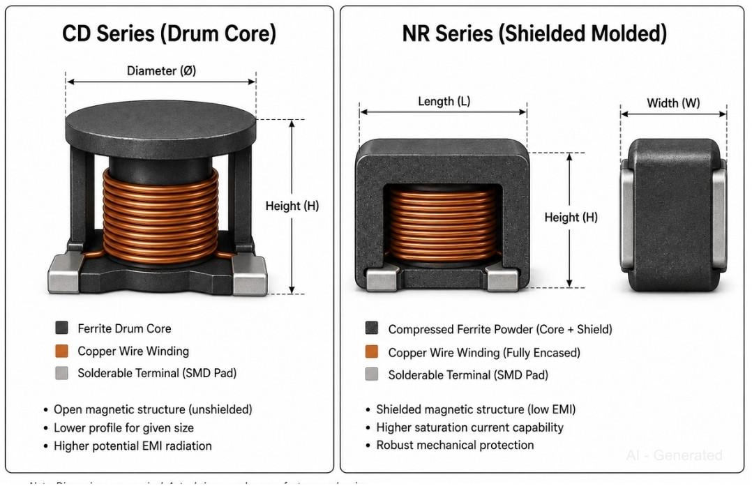
Figure: Comparison of a CD series drum-core inductor and an NR series shielded molded inductor, with dimension arrows labeled.
CD32 and CD43 Packages
Compact drum-core power inductors suited to low-to-medium current applications.
- CD32 (dia 3.2 x 2.5 mm) fits in tight power stages where vertical height is a constraint, common on ultra-thin portable boards
- CD43 (dia 4.3 x 3.0 mm) handles up to 3 A, practical for lightweight DC-DC converters and USB power conditioning
Both are commonly used in light motor drivers and single-cell Li-ion charger circuits At this size, heat dissipation through the surrounding PCB copper becomes increasingly important, especially in enclosed designs without airflow. Do not rely on the component alone to manage temperature rise.
CD54 and CD73/CD75 Packages
Step up to these when saturation margin and heat dissipation become the primary concerns.
- CD54 (dia 5.4 x 4.0 mm) supports up to 4 A. The larger ferrite drum body raises the saturation threshold meaningfully over CD43
- CD73 (dia 7.3 x 3.0 mm) covers 1-6 A with a wider base that distributes heat more effectively across the board surface
- CD75 shares the same diameter as CD73 but adds height (5.0 mm), improving inductance density without increasing the PCB footprint. Useful when horizontal space is limited.
Suited for mid-power switching regulators, 12 V rail converters, and multi-output power trees
NR3015 and NR6045 Packages
The NR series uses a fully shielded molded construction, making it the most EMI-friendly format in this category.
- Lower radiated noise than open-drum CD inductors
- NR3015 is compact (3 x 3 x 1.5 mm) and handles up to 3 A, a common choice for tight power stages
- NR6045 scales to 10 A+, widely used in: Buck converters, Embedded system power rails, Battery-powered devices needing clean regulation
High-Current Shielded SMD Power Inductor Sizes
When current demands push past 10 A in GPUs, automotive power stages, and industrial motor drives, standard CD and NR packages are no longer sufficient. These larger shielded inductors are designed specifically for that operating range.
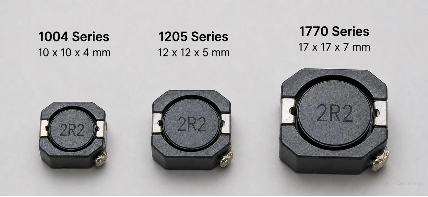
Figure: 1004, 1205, and 1770 series SMD power inductors placed beside a ruler showing progressive size increase from 10 x 10 mm to 17 x 17 mm.
1004 and 1205 Inductor Series
- Large magnetic cores reduce DCR significantly compared to mid-range power packages
- 1004 handles up to 15 A+ with good efficiency at high switching frequencies. Many low-inductance variants achieve DCR values well below 10 mOhm.
- 1205/1207 delivers even lower DCR at higher saturation thresholds, important in GPU power delivery networks and server board VRMs where transient current spikes are large and fast These packages benefit from their large copper pad area for improved thermal transfer into the PCB plane, which reduces dependence on forced airflow in many industrial rack designs.
1770 Inductor Series
- Designed for 20-60 A continuous operation, a range no other SMD package category reliably covers
- The larger package footprint improves thermal transfer into the PCB copper plane, making self-heating far more manageable than stacking multiple smaller inductors
- Common in EV battery management systems, industrial inverters, high-current FPGA core supplies, and telecom rectifier stages
- DCR values in this series can drop below 1 mOhm in low-inductance parts, which has a direct and measurable impact on converter efficiency at high load. It is not a compact component, but for high-current work, nothing replaces the physics of core volume.
Note
Check out the current JLCPCB quotation options when you are ready to price out a board utilizing these heavier-duty parts.
How to Select the Right SMD Inductor Size
For Compact RF Devices
- 0402 or 0603 for RF matching, antenna tuning, and impedance networks
- Multilayer chip inductors where self-resonant frequency and Q-factor are critical
- Accept the higher DCR. At signal levels it is irrelevant.
For General Electronics
- 0603 or 0805 for most filtering, signal conditioning, and low-current supply bypassing
- Balance of PCB space, thermal handling, and assembly reliability
- Easily available in standard SMT assembly component libraries
For Power Supplies
- CD54, NR6045 for mid-range switching regulators (1-10 A range)
- Choose shielded (NR series) when EMI compliance is a concern
- Match Isat to your peak current with at least 20% margin
For High Current Designs
- 1205 or 1770 series for anything pushing 15 A and above
- Prioritize low DCR and high Isat over footprint size
- Thermal management becomes as important as the inductor selection itself. Common assembly-friendly packages like 0805, 1206, and NR-series inductors are well-supported in turnkey PCB manufacturing workflows, with standardized footprints that simplify sourcing and fabrication.
How SMD Inductor Size Affects Electrical Performance
This is where package choice becomes a system-level decision, not just a layout preference.
Inductance Value
Inductance (measured in uH or mH) is set by the application. Your converter topology, switching frequency, and ripple current budget determine what you need. Package size does not set inductance directly, but a given inductance value in a smaller package will typically have higher DCR and lower saturation current.
RMS Current Rating (Irms)
- The maximum continuous current the inductor can carry without excessive self-heating
- Usually specified at a 40 degrees Celsius temperature rise above ambient
- Larger packages, with more copper cross-section, support higher Irms
Saturation Current (Isat)
This is the specification engineers most often underestimate.
- Isat is the current at which inductance drops by a defined percentage (typically 20-30%)
- Beyond Isat: ripple current increases sharply, efficiency drops, and thermal runaway becomes a serious risk
- Always design with headroom. If your peak current is 3 A, do not use an inductor rated at exactly 3 A Isat
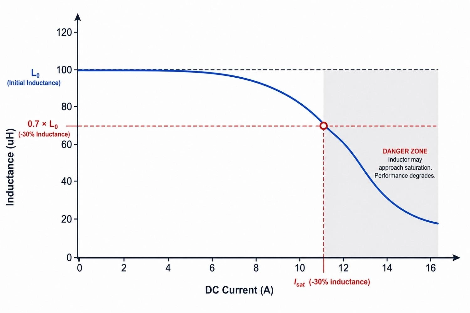 Figure: Inductance vs. DC current curve for an SMD power inductor with the Isat threshold and over-saturation region marked.
DCR (DC Resistance)
DCR is a direct efficiency tax.
- Smaller packages = tighter, thinner windings = higher DCR
- Power dissipated as heat = I2 x DCR
- In battery-powered designs, DCR is often the deciding factor between two otherwise equivalent packages
| Package | Relative DCR | Efficiency Impact |
|---|---|---|
| 0402 chip | High | Negligible at signal levels |
| 0805 chip | Moderate | Low |
| CD43 power | Low | Moderate, watch at 2 A+ |
| NR6045 | Very low | Minimal, suited for high current |
| 1770 series | Extremely low | High-current efficiency optimized |
PCB Footprint and Layout Considerations for SMD Inductors
Package dimensions alone do not define your footprint. Pad geometry, courtyard clearance, and keep-out zones vary by manufacturer. Two 0805 inductors from different vendors can require completely different land patterns.
Core layout rules:
- Always use the manufacturer's recommended solder pad design from the specific datasheet, not a generic footprint
- Keep the switching loop short. Minimize the area enclosed by the inductor, input capacitor (Cin), and switch node
- Add copper pours or thermal vias under power inductors to aid heat dissipation
- Avoid routing sensitive signal traces directly under shielded inductors. Despite the shielding, fringe fields exist
- For unshielded inductors (drum core), enforce a minimum clearance to other magnetically sensitive components
- Keep high-current inductors away from sensitive analog or RF sections of the board
Note
Important: Component footprints vary significantly across manufacturers. Verify the exact land pattern before sending to fabrication. A mismatch here means a costly board respin.
Common SMD Inductor Types
Beyond size, the construction method determines how an inductor behaves under load. The three dominant types each suit a different set of applications. Understanding these nuances is a key part of distinguishing PCBA vs PCB design considerations.
Different SMD inductor types are available across multiple package sizes, depending on current, frequency, and thermal requirements.
Multilayer Chip Inductors
Built by stacking ferrite layers with internal conductive patterns. No wire winding involved.
- Extremely compact, down to 0201 in specialized RF designs
- High self-resonant frequency, making them suited for GHz-range RF filtering
- Low current capability (typically well under 1 A)
- Used in antenna matching, RF front-end filtering, and impedance networks in smartphones and IoT modules
Wire-Wound Chip Inductors
A fine copper wire wound around a ferrite or ceramic core, then terminated and encased.
- Better Q-factor than multilayer at the same package size
- Higher current handling than multilayer at equivalent footprints
- Available from 0402 through 1210 in chip form
- Common in signal filtering, impedance matching, and general RF applications where multilayer inductance tolerance is insufficient
Shielded Molded Power Inductors
The NR and CD series discussed earlier fall into this category. The winding is embedded in a compressed ferrite powder matrix that forms both the core and the shielding.
- Low EMI radiation compared to open-drum or unshielded types
- Excellent thermal performance due to the distributed ferrite mass
- Handles continuous DC current from 1 A up to 60 A+ depending on package
- The default choice for modern DC-DC converters, battery-powered devices, and any design where EMI compliance matters
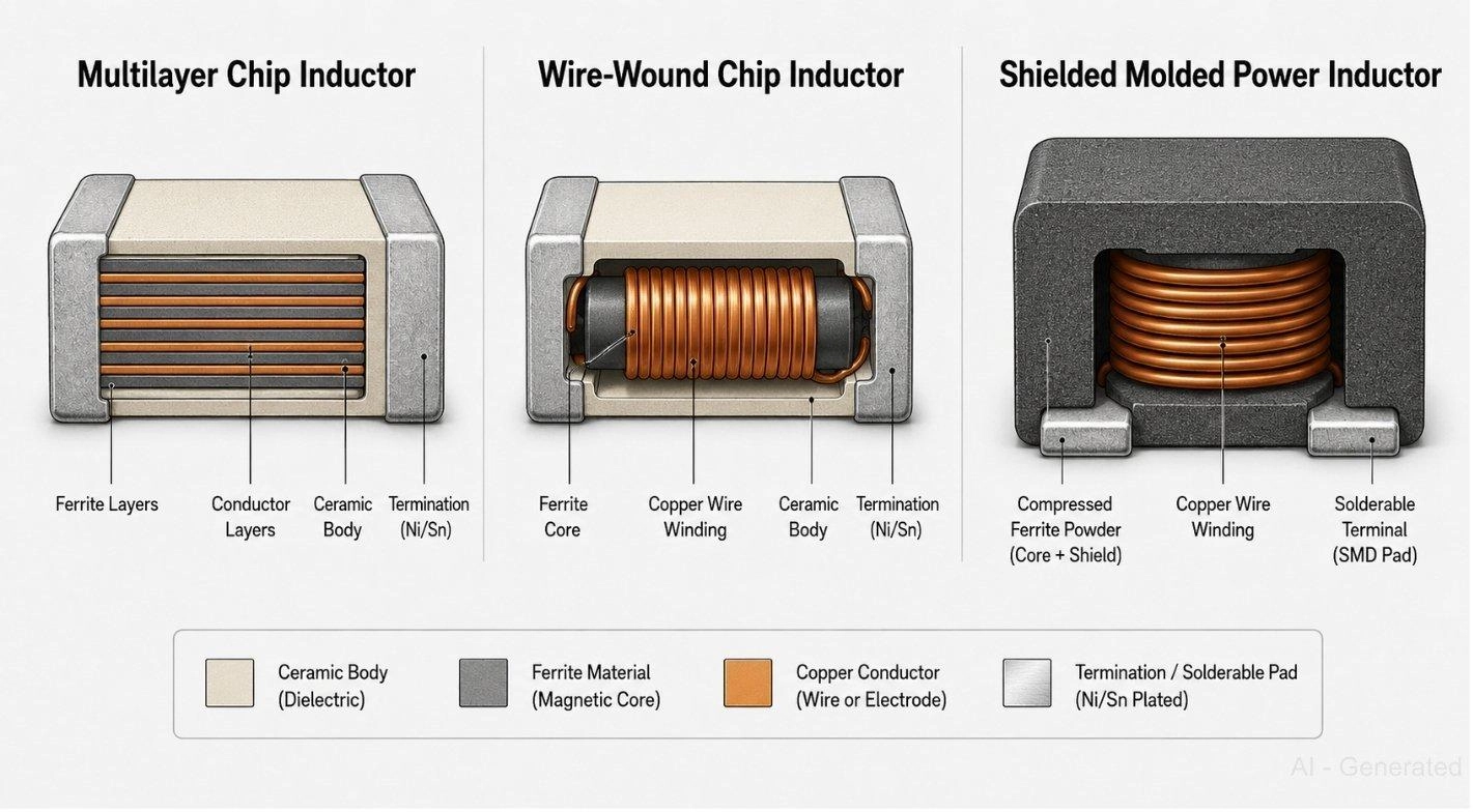
Figure: Comparison of multilayer chip, wire-wound chip, and shielded molded SMD inductor construction types.
FAQs about SMD Inductor Size
Q: What is the most common SMD inductor size?
For general electronics, 0603 and 0805 are the most widely used. For power applications, the NR3015 and CD43 are common choices across mid-range designs, offering a good balance of size and efficiency.
Q: What does the 0603 inductor code signify?
It is an imperial code detailing the physical dimensions: 06 indicates a length of 0.06 inches (approx 1.6 mm), and 03 signifies a width of 0.03 inches (approx 0.8 mm). Its exact metric equivalent is 1608.
Q: Are larger power inductors always the better choice?
Not universally. While larger packages offer advantages like lower DCR, higher current ratings, and superior thermal handling, they consume valuable board area. Component sizing is always an engineering trade-off based on specific application requirements.
Q: Which surface mount inductor packages manage the highest current loads?
The 1770 series is engineered to support demanding continuous loads of 20-60 A, making it the premier choice for industrial motor drives and automotive high-current power stages.
Q: Why do power inductor specifications highlight height dimensions?
The height of the core directly dictates the component's magnetic cross-section. A taller ferrite core can handle more magnetic flux before saturating, which establishes both the saturation current and thermal mass limits.
Q: Can a PCB layout swap a 0603 inductor for an 0805?
Electrically, this may work if both parts share identical inductance and current specifications. However, physically they are not drop-in replacements. You must update your CAD software to verify pad geometry and courtyard clearance to avoid manufacturing defects.
Conclusion
SMD inductor size determines DCR, current rating, saturation headroom, and how much heat the design has to manage. RF and signal work stays in the 0402-1206 chip range; power conversion moves to shielded CD or NR series; anything above 15 A needs a 1205 or 1770. Construction type matters as much as footprint. A multilayer chip and a shielded power inductor can share a package code but are not interchangeable.
For prototyping and SMT assembly with standard inductor packages, check out the JLCPCB PCB assembly services, which offer turnkey manufacturing with an integrated parts library to simplify sourcing before your BOM is completely finalized.
Popular Articles
• SMD Capacitor Sizes: Complete Size Chart and Selection Tips for PCB Design and Assembly
• SMD Diode Code Lookup: Full List, Marking Guide & Identification [2026 Guide]
• SMD Resistor Package Sizes: Complete Size Chart, Footprints & How to Choose
• SMD Capacitor Codes: Identification, Markings, and Polarity
• How to Solder SMD Components Like a Pro [2026 Updated]
Keep Learning
What Is the ESP32? A Complete Guide to Features, Architecture, Modules, Programming, and Applications
From Wi-Fi-enabled temperature sensors and wearable health monitors to industrial gateways and AI-powered cameras, the ESP32 microcontroller has become one of the world's most widely adopted wireless embedded platforms. Combining a powerful processor with integrated Wi-Fi and Bluetooth, it lets engineers build connected devices without separate networking hardware. This guide covers ESP32 specifications, architecture, the full family of variants, development boards, programming tools, and real-world E......
How to Choose the Right STM32 Microcontroller: Compare Series, Cortex-M Cores, and Key Features
STMicroelectronics ships thousands of STM32 MCU part numbers across more than a dozen series, and that variety is exactly what makes STM32 microcontroller selection difficult. Pick the wrong family, and you pay for it later: oversized BOM cost, wasted power budget, or a board respin when a peripheral turns out to be missing. This STM32 microcontroller selection guide breaks the decision into a five-step framework built on practical engineering criteria, not datasheet marketing copy, so you can match a......
SMD Transistor Code Lookup: Identify Markings, Pinout & Multimeter Test Guide
Repairing a circuit board often brings a familiar frustration: staring at a tiny, three-legged black component with an obscure two- or three-letter code. Whether troubleshooting a bare prototype or a mass-produced PCBA, knowing how to quickly decode these surface-mount device (SMD) markings is an essential skill for any electronics engineer or repair technician. In this comprehensive guide, you will learn: 1. How to decode SMD transistor marking codes 2. How to identify BJT vs MOSFET types 3. How to f......
SMD Capacitor Sizes: Complete Size Chart and Selection Tips for PCB Design and Assembly
In the world of modern electronics, surface mount devices (SMDs) have revolutionized board design, allowing for smaller, faster, and more efficient printed circuit boards. When designing a PCB, selecting the correct SMD capacitor sizes is one of the most critical decisions an engineer must make to ensure both electrical reliability and manufacturability. In this article, you will find practical, authoritative guidance on: Comprehensive SMD capacitor size charts for quick reference. How to read imperia......
SMD Diode Code Lookup: Full List, Marking Guide & Identification [2026 Guide]
In modern electronics, surface-mount diodes are used everywhere - from power input protection circuits to high-speed signal routing. Because these components are extremely small, manufacturers cannot print full part numbers on their bodies. Instead, they use short marking codes such as A2, M7, SS14, or SL, which often confuse beginners during PCB repair, reverse engineering, or component replacement. This guide explains how to decode SMD diode codes, identify polarity, test components using a multimet......
Thin Film vs. Thick Film Resistors: Key Differences & Selection Guide
Key Takeaways Default to thick film resistors for most designs. They are cost-effective, robust, and ideal for pull-ups, LED current-limiting, digital circuits, and surge-prone applications. Choose thin-film resistors whenever a resistor defines an analog quantity, such as a voltage divider, reference network, gain-setting circuit, or current-sensing signal chain. Their tight tolerance and low TCR help maintain measurement accuracy over temperature and time. Most PCB designs use thick film or thin fil......