
How to Read SMD Resistor Values: Codes, Charts, and Identification Guide
8 min
- Quick Checklist to Identify SMD Resistor Value
- SMD Resistor Value Chart
- Common SMD Resistor Value Examples
- SMD Resistor Package Sizes
- How to Read SMD Resistor Codes (3-Digit, 4-Digit & EIA-96)
- Common Mistakes When Reading SMD Resistor Codes
- How to Measure SMD Resistor Values When Codes Are Missing
- Sourcing and Assembling SMD Resistors for PCB Projects at JLCPCB
- FAQs
- Conclusion
An SMD resistor value is identified using numeric or alphanumeric marking codes printed on the surface of chip resistors. These codes represent resistance in ohms using standardized 3-digit, 4-digit, or EIA-96 systems.
This guide breaks down the 3-digit, 4-digit, and EIA-96 marking systems so you can decode, calculate, and replace any SMD resistor with confidence.
Quick Checklist to Identify SMD Resistor Value
Understanding SMD resistor values simply requires recognizing which standardized system is printed on the chip.
- Count the digits: 3 numbers (5% tolerance) or 4 numbers (1% tolerance)?
- Check for letters: Is there an "R" (decimal), or a letter like "C" (EIA-96)?
- Refer to the chart: Use a lookup table to confirm the math.
- Measure if unmarked: Isolate 0402/0201 packages and test with a DMM.
SMD Resistor Value Chart
Below is an expanded quick-reference chart containing both low-ohm and high-ohm markings across all three systems. Use this chart for rapid bench identification without recalculating resistor values.
Marking Code | Significant Figures | Multiplier | Calculated Value | System Type |
|---|---|---|---|---|
100 | 10 | × 10^0 (1) | 10 Ω | 3-Digit (5%) |
101 | 10 | × 10^1 (10) | 100 Ω | 3-Digit (5%) |
220 | 22 | × 10^0 (1) | 22 Ω | 3-Digit (5%) |
221 | 22 | × 10^1 (10) | 220 Ω | 3-Digit (5%) |
330 | 33 | × 10^0 (1) | 33 Ω | 3-Digit (5%) |
331 | 33 | × 10^1 (10) | 330 Ω | 3-Digit (5%) |
680 | 68 | × 10^0 (1) | 68 Ω | 3-Digit (5%) |
4R7 | 4.7 | N/A | 4.7 Ω | Decimal Code |
103 | 10 | × 10^3 (1,000) | 10 kΩ | 3-Digit (5%) |
104 | 10 | × 10^4 (10,000) | 100 kΩ | 3-Digit (5%) |
105 | 10 | × 10^5 (100,000) | 1 MΩ | 3-Digit (5%) |
472 | 47 | × 10^2 (100) | 4.7 kΩ | 3-Digit (5%) |
1002 | 100 | × 10^2 (100) | 10 kΩ | 4-Digit (1%) |
01B | 100 | × 10 | 1 kΩ | EIA-96 (1%) |
01C | 100 | × 100 | 10 kΩ | EIA-96 (1%) |
Table: SMD resistor value chart showing 3-digit and EIA codes
Common SMD Resistor Value Examples
The following quick examples explain how common SMD resistor codes translate into actual resistance values.
Break down the most frequently encountered SMD resistor codes using these quick-reference mini-cards:
102 Resistor Value- Formula: 10 × 102
- Result: 1000Ω (1kΩ)
- Formula: 10 × 10³
- Result: 10,000Ω (10kΩ)
- Formula: 10 × 10⁴
- Result: 100,000Ω (100kΩ)
- Formula: 10 × 105
- Result: 1,000,000Ω (1MΩ)
- Formula: 47 × 100
- Result: 47Ω (Note: The 3rd digit '0' means no zeros are added)
- Formula: 47 × 10²
- Result: 4,700Ω (4.7kΩ)
- Formula: 22 × 10⁰
- Result: 22 × 1 = 22Ω (Note: The 3rd digit '0' means no zeros are added)
- Formula: "R" replaces the decimal point
- Result: 4.7Ω
- Formula: Lookup '01' (100) × Multiplier 'C' (100)
- Result: 10,000Ω (10kΩ)
- Formula: N/A (Jumper)
- Result: 0Ω (Used to bridge signals or configure hardware)
SMD Resistor Package Sizes
SMD resistor package size influences the marking system used. The electronics industry commonly uses imperial codes (such as 1206, 0805, and 0603) to define component dimensions. Smaller packages enable higher PCB routing density and help reduce parasitic inductance and capacitance in high-frequency designs.
Package size is also closely related to power rating and marking visibility:
- 1206 and 0805 Packages: Larger components that are typically marked with 3- or 4-digit codes. Typical power ratings: 1206 (~0.25W), 0805 (~0.125W)
- 0603 Packages: Standard size, often marked with condensed EIA-96 codes (~0.1W).
- 0402 and 0201 Packages: Microscopic components for high-density electronics. Rarely marked due to space limitations (~0.062W). You need a schematic or a multimeter to identify them.
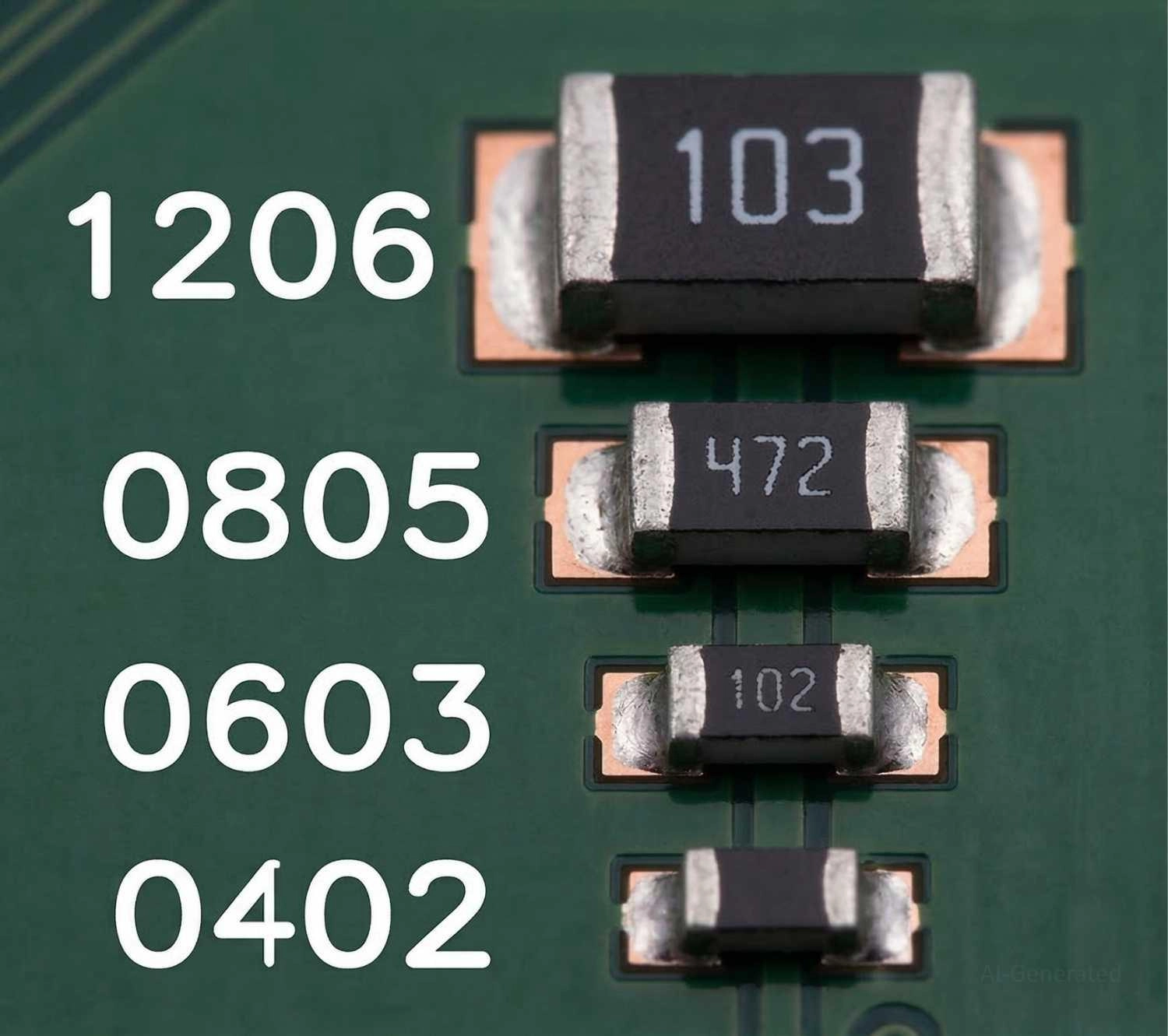
Figure: SMD resistor package size comparison
How to Read SMD Resistor Codes (3-Digit, 4-Digit & EIA-96)
SMD resistor values are identified using standardized marking codes printed on the component.
The vast majority of marked SMD resistors use a simple mathematical system based on significant figures and a multiplier.
General Formula:
Resistance = Significant digits × 10^(multiplier)
This system is split into two categories based on the resistor's manufacturing tolerance.
The 3-Digit System (Standard 5% Tolerance)
Used for standard-precision SMD resistors (typically 5% tolerance), the 3-digit system is straightforward: the first two digits represent the significant figures, and the third digit is the multiplier (power of 10).
For example, 103 = 10 × 10³, or 10kΩ.
For decimal values under 10 ohms, the letter "R" acts as a decimal point. For example, 4R7 = 4.7Ω.
The 4-Digit System (Precision 1% Tolerance)
Used for precision resistors (usually 1% tolerance), the 4-digit system adds an extra significant figure. The first three digits are significant, and the fourth is the multiplier.
For example, 1002 = 100 × 10² = 10kΩ
For sub-ohm current sense resistors in power circuits, "M" or "m" represents a decimal point in milliohms
For example, 0M50 = 0.05Ω (50mΩ)
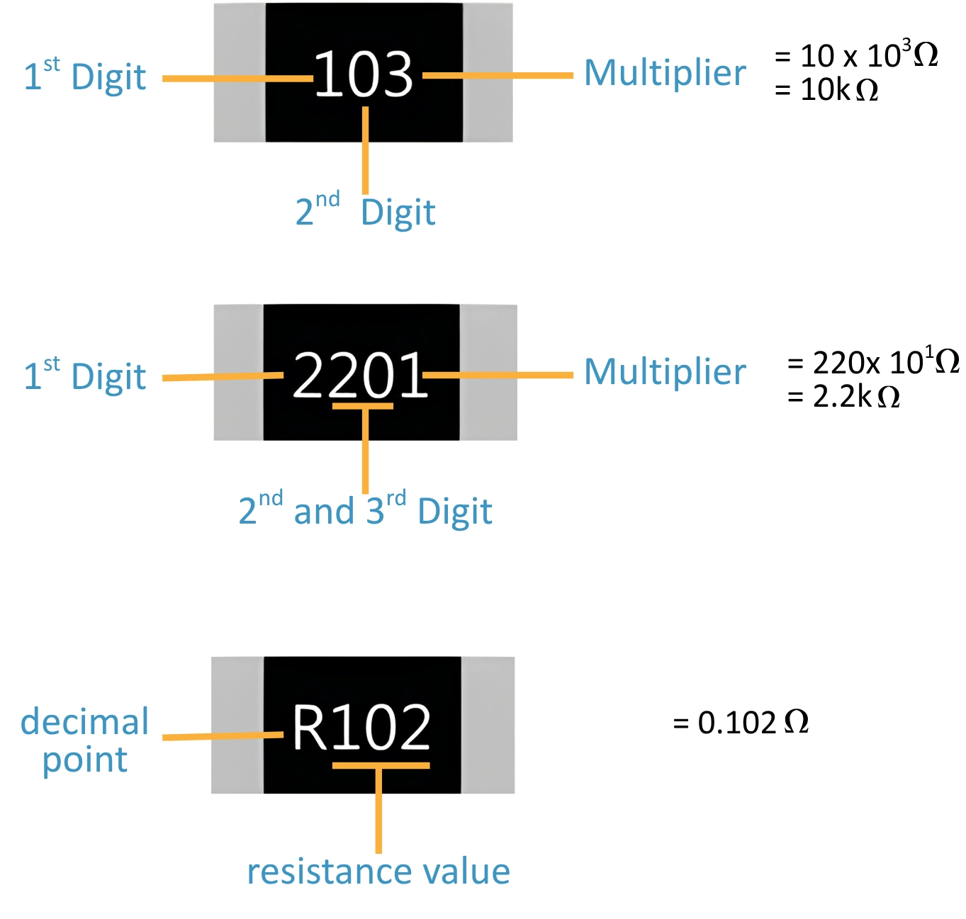
Figure: The step-by-step calculation of 3-digit and 4-digit SMD resistor marking codes.
The EIA-96 System (1% Tolerance for 0603 & Smaller)
Printing four legible digits on tiny 0603 packages is physically impractical. The Electronic Industries Alliance solved this with the EIA-96 standard (based on the IEC 60062 standard marking codes).
This condensed 3-character code is used exclusively for 1% tolerance resistors and requires a reference table to decode:
- First two numbers (01 to 96): Point to a base value on the standardized lookup table (e.g., '01' = 100).
- Final letter: Represents the mathematical multiplier (e.g., Z = ×0.001, A = ×1, B = ×10, C = ×100).
Because decoding EIA-96 values requires memorizing 96 base codes, engineers rely on lookup charts. You can view the full table in our complete resistor marking reference.
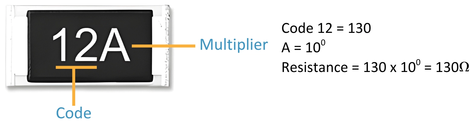
Figure: EIA96 resistor code identification
Common Mistakes When Reading SMD Resistor Codes
Even experienced engineers can misread SMD resistor codes, especially when working with tiny packages or contaminated components.
Misreading SMD resistor codes can easily lead to incorrect resistor values, causing circuit malfunction or signal drift.
- Confusing 103 vs 1003: Both equal 10kΩ, but 103 is a 5% tolerance part, while 1003 is a precision 1% part. Swapping them causes signal drift.
- Wrong Multiplier Interpretation: Reading 220 as 220 ohms. The last digit is the power of 10. (220 is 22 ohms; 221 is 220 ohms).
- Confusing "R" Marking with a Tolerance Letter: 4R7 signifies 4.7Ω. However, a part numbered 4R7F means 4.7Ω with an 'F' denoting a 1% tolerance.
- Misreading Due to Flux Residue: Burnt flux can easily make a 3 look like an 8 or 0, causing disastrous swaps. Always clean the component first.
- Measuring Resistors In-Circuit: Parallel paths give artificially low readings. Always lift one pad to isolate the component.
How to Measure SMD Resistor Values When Codes Are Missing
When dealing with unmarked microscopic packages (like 0402 or 0201), use this strict testing workflow:
- Microscope: Check for faint laser-etched codes hidden by flux residue.
- Check BOM: Cross-reference the component's reference designator (e.g., R14) with your schematic.
- Lift One Pad: Isolate the component to break the circuit before measuring.
- Measure: Use a Digital Multimeter (DMM) for general troubleshooting, or an LCR Meter for sub-ohm precision.
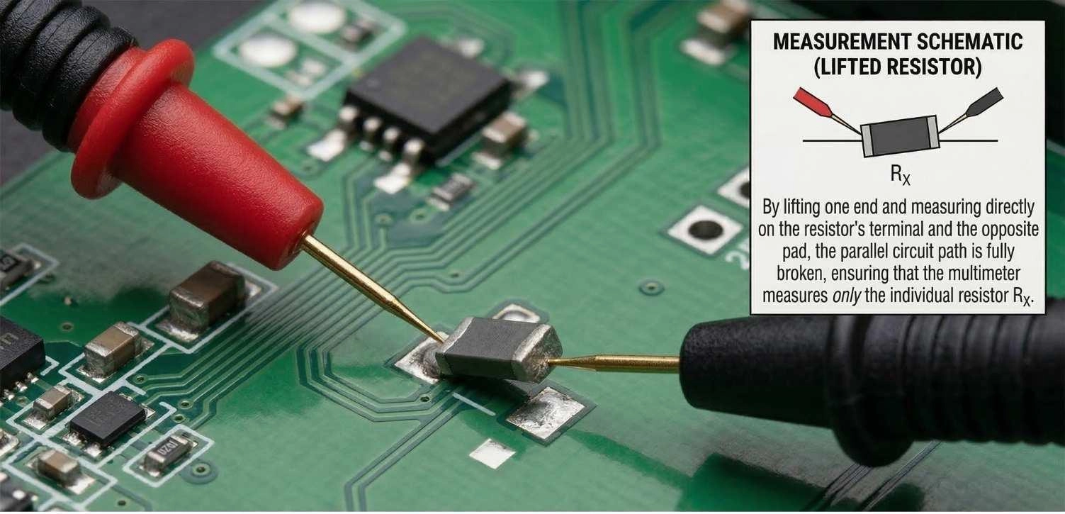
Figure: Multimeter probes testing an isolated SMD resistor with one pad desoldered from the PCB.
Sourcing and Assembling SMD Resistors for PCB Projects at JLCPCB
Hand-reading SMD values is essential for prototyping, but inefficient at scale. Reliable hardware manufacturing relies on a meticulously organized, digital Bill of Materials (BOM) rather than manual visual identification.
Strict CAD exports dictate exact values and footprints. Sourcing authentic, reel-packaged components matching your BOM is critical - you can explore components on the JLCPCB Parts Library.
During automated assembly, high-speed pick-and-place machines bypass visual checks, pulling parts directly from mapped reels based on BOM coordinates. Scaling up with a reliable PCB Assembly service like JLCPCB reduces manual identification errors and ensures production consistency.
FAQs
Q: What does 104 mean on a resistor?
The code 104 is a 3-digit SMD marking. The first two digits (10) are multiplied by 10⁴, giving 100,000 ohms (100kΩ).
Q: What does a 000 resistor mean?
A resistor marked 0 or 000 is a zero-ohm jumper. It has virtually no resistance and is used purely to bridge traces or configure hardware on a PCB.
Q: How do I identify an SMD resistor value without removing it?
Measure the approximate resistance with a multimeter and compare it with the schematic. If it reads significantly lower, parallel components are affecting the reading, and you must unsolder one pad to isolate it.
Q: Why do some SMD resistors have no marking?
Due to extreme size limitations (such as on 0402 or 0201 packages) and specific manufacturer choices, printing legible codes is often physically impractical.
Q: What is the EIA-96 code system?
It is a 3-character alphanumeric system (e.g., 01C) specifically developed to mark 1% precision resistors on tiny packages (0603 and smaller) where printing four numbers is physically impractical.
Conclusion
Mastering SMD resistor decoding speeds up troubleshooting, ensures correct component substitution, and improves overall reliability in high-density PCB designs.
Popular Articles
• SMD Capacitor Sizes: Complete Size Chart and Selection Tips for PCB Design and Assembly
• SMD Diode Code Lookup: Full List, Marking Guide & Identification [2026 Guide]
• SMD Resistor Package Sizes: Complete Size Chart, Footprints & How to Choose
• SMD Capacitor Codes: Identification, Markings, and Polarity
• How to Solder SMD Components Like a Pro [2026 Updated]
Keep Learning
What Is the ESP32? A Complete Guide to Features, Architecture, Modules, Programming, and Applications
From Wi-Fi-enabled temperature sensors and wearable health monitors to industrial gateways and AI-powered cameras, the ESP32 microcontroller has become one of the world's most widely adopted wireless embedded platforms. Combining a powerful processor with integrated Wi-Fi and Bluetooth, it lets engineers build connected devices without separate networking hardware. This guide covers ESP32 specifications, architecture, the full family of variants, development boards, programming tools, and real-world E......
How to Choose the Right STM32 Microcontroller: Compare Series, Cortex-M Cores, and Key Features
STMicroelectronics ships thousands of STM32 MCU part numbers across more than a dozen series, and that variety is exactly what makes STM32 microcontroller selection difficult. Pick the wrong family, and you pay for it later: oversized BOM cost, wasted power budget, or a board respin when a peripheral turns out to be missing. This STM32 microcontroller selection guide breaks the decision into a five-step framework built on practical engineering criteria, not datasheet marketing copy, so you can match a......
SMD Transistor Code Lookup: Identify Markings, Pinout & Multimeter Test Guide
Repairing a circuit board often brings a familiar frustration: staring at a tiny, three-legged black component with an obscure two- or three-letter code. Whether troubleshooting a bare prototype or a mass-produced PCBA, knowing how to quickly decode these surface-mount device (SMD) markings is an essential skill for any electronics engineer or repair technician. In this comprehensive guide, you will learn: 1. How to decode SMD transistor marking codes 2. How to identify BJT vs MOSFET types 3. How to f......
SMD Capacitor Sizes: Complete Size Chart and Selection Tips for PCB Design and Assembly
In the world of modern electronics, surface mount devices (SMDs) have revolutionized board design, allowing for smaller, faster, and more efficient printed circuit boards. When designing a PCB, selecting the correct SMD capacitor sizes is one of the most critical decisions an engineer must make to ensure both electrical reliability and manufacturability. In this article, you will find practical, authoritative guidance on: Comprehensive SMD capacitor size charts for quick reference. How to read imperia......
SMD Diode Code Lookup: Full List, Marking Guide & Identification [2026 Guide]
In modern electronics, surface-mount diodes are used everywhere - from power input protection circuits to high-speed signal routing. Because these components are extremely small, manufacturers cannot print full part numbers on their bodies. Instead, they use short marking codes such as A2, M7, SS14, or SL, which often confuse beginners during PCB repair, reverse engineering, or component replacement. This guide explains how to decode SMD diode codes, identify polarity, test components using a multimet......
Thin Film vs. Thick Film Resistors: Key Differences & Selection Guide
Key Takeaways Default to thick film resistors for most designs. They are cost-effective, robust, and ideal for pull-ups, LED current-limiting, digital circuits, and surge-prone applications. Choose thin-film resistors whenever a resistor defines an analog quantity, such as a voltage divider, reference network, gain-setting circuit, or current-sensing signal chain. Their tight tolerance and low TCR help maintain measurement accuracy over temperature and time. Most PCB designs use thick film or thin fil......