
Diode Type Guide: How to Choose the Right Diode for PCB and Product Design
18 min
- Diode Types Chart (Quick Comparison)
- Common Types of Diodes and Their Applications
- How to Choose the Right Diode for Your Circuit
- Common Mistakes When Selecting Diode Types
- SMD Diode Types: Useful Engineering Considerations
- Through-Hole vs SMD Diode Packages
- Why Diode Selection Matters in Modern Electronics
- What Is a Diode and How Does It Work?
- Key Diode Parameters Engineers Must Understand
- FAQs on Diode Types
- Conclusion
Modern electronics rely on highly specialized diode types for power conversion, ESD protection, signal detection, and high-frequency switching. Choosing the wrong diode doesn't just reduce efficiency; it also generates excess heat, introduces switching losses, and can even damage sensitive circuits during voltage transients. Choosing the right component ensures a reliable board, whether you are wiring a prototype or scaling to low-volume PCB assembly.
In this guide, you'll learn:
- How do different diode types function internally
- Where to use rectifier, Schottky, Zener, TVS, LED, and fast recovery diodes
- How package choices directly affect PCB thermal performance
- How engineers select the right diode for modern designs
Diode Types Chart (Quick Comparison)
| Diode Type | Speed | Forward Voltage (Vf) | Max Reverse Voltage | Reverse Recovery (trr) | Primary Use | Typical Package |
|---|---|---|---|---|---|---|
| Rectifier | Slow | 0.7-1.1V | Up to 1000V | 1-10µs | AC-DC conversion | DO-41 / SMA |
| Schottky | Very fast | 0.15-0.45V | 20-200V | ~0 (majority carrier) | SMPS, low-loss rectification | SMA / SMB |
| Zener | Medium | Fixed breakdown | Defined Vz | ~100ns | Voltage regulation, clamping | SOD-123 / DO-35 |
| TVS | Sub-nanosecond | Clamping Vc | Surge-rated | Picoseconds | ESD/transient protection | SMAJ / SMBJ |
| LED | Medium | 1.2-3.5V (color-dependent) | 5-50V | N/A | Lighting, indication | 0603 / 5050 |
| Photodiode | Fast | N/A (reverse biased) | 20-100V | 1-10ns | Optical sensing | TO-18 / 1206 |
| Fast Recovery | Fast | 0.8-1.2V | 100-1200V | 25-500ns | High-frequency rectification | DO-41 / TO-220 |
| Laser Diode | N/A | 1.5-3.0V | Low (5-20V) | N/A | Optical communication, LiDAR | TO-56 |
Common Types of Diodes and Their Applications
The different types of diodes below are optimized for completely different electrical behaviors. What works perfectly for a low-frequency AC circuit will fail instantly in a high-speed switching environment. Understanding their specific use cases is critical for modern design.
#1 Rectifier Diodes
The workhorse of power electronics. Rectifier diodes convert AC to DC and are optimized for high voltage and current handling rather than speed.
Key characteristics:
- Forward voltage: ~0.7-1.1V
- Switching speed: Slow (trr typically 1-10µs)
- Reverse voltage: Up to 1000V (1N4007)
- Cost: Very low
Typical applications:
- Bridge rectifiers in linear power supplies
- Freewheeling diodes in relay driver circuits
- Low-frequency AC-DC conversion
The 1N400x family (1N4001 to 1N4007) remains the most widely used through-hole rectifier series. Each diode in the 1N400x family is rated for 1A average forward current with reverse voltages from $50V$ (1N4001) to $1000V$ (1N4007). For SMD designs, the M7 (SMA package) is the direct equivalent.
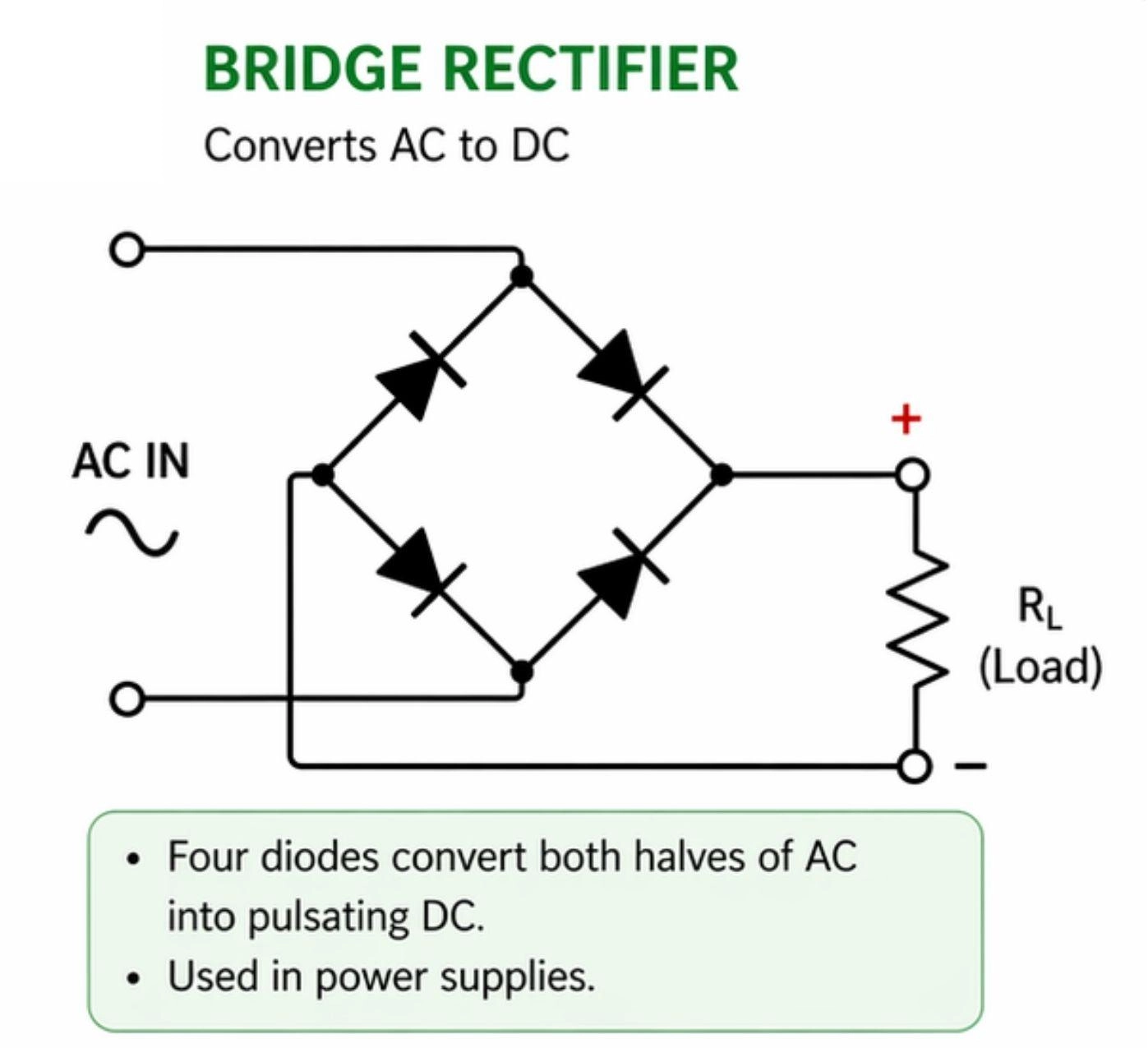
Figure: Standard bridge rectifier. Four rectifier diodes in this configuration convert full-wave AC to pulsating DC.
#2 Schottky Diodes
The go-to choice for modern switching power supplies. Schottky diodes are built from a metal-semiconductor junction rather than a P-N junction, which fundamentally changes their behavior.
Key characteristics:
- Forward voltage: 0.15-0.45V (significantly lower than silicon)
- Switching speed: Very fast (trr near-zero, majority carrier device)
- Reverse voltage: Typically 20-200V (lower than standard diodes)
- Reverse leakage: Higher than standard diodes, especially at elevated temperatures
Typical applications:
- Buck and boost converter output rectification
- Solar charge controllers
- Reverse polarity protection
- OR-ing circuits in redundant power systems
- USB power path protection
Popular parts: SS14 (SMA, 1A/40V), SS34 (SMA, 3A/40V), 1N5819 (DO-41, 1A/40V), MBRS360 (SMC, 3A/60V)
Engineering tradeoff to know
Schottky diodes have higher reverse leakage current that increases sharply with temperature. Because reverse leakage rises with temperature, Schottky diodes can enter thermal runaway if heatsinking and copper area are insufficient. In high-temperature environments (automotive, under-hood), this leakage can also become significant enough to affect standby power consumption.
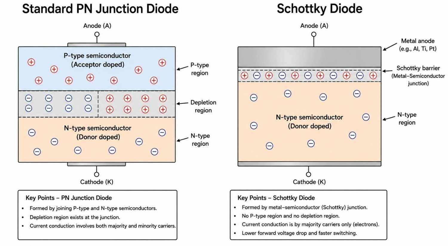
Figure: Comparison of internal structure between a standard PN junction diode and a Schottky diode, showing the metal-semiconductor junction
#3 Zener Diodes
Zener diodes are designed to operate in controlled reverse breakdown. Unlike a standard diode, where reverse breakdown is destructive, a Zener is engineered to break down at a precise, stable voltage and stay there.
Key characteristics:
- Operates in reverse bias at defined breakdown voltage (Vz)
- Available in standard values from ~2.4V to 200V
- Tolerance: ±5% (standard), ±2% (precision series)
- Power ratings: typically 200mW to 5W
Typical applications:
- Voltage clamping and reference
- MCU GPIO overvoltage protection
- Simple shunt regulators (low current applications)
- Crowbar circuit trigger references
Popular series: BZT52 (SOD-123, 200mW), BZX55 (DO-35, 500mW), 1N47xx (DO-41, 1W)
At voltages below ~5.6V, Zener breakdown dominates (negative temperature coefficient). Above ~5.6V, avalanche breakdown dominates (positive temperature coefficient). The 5.1V Zener is often chosen for references because the two mechanisms partially cancel, giving better temperature stability.
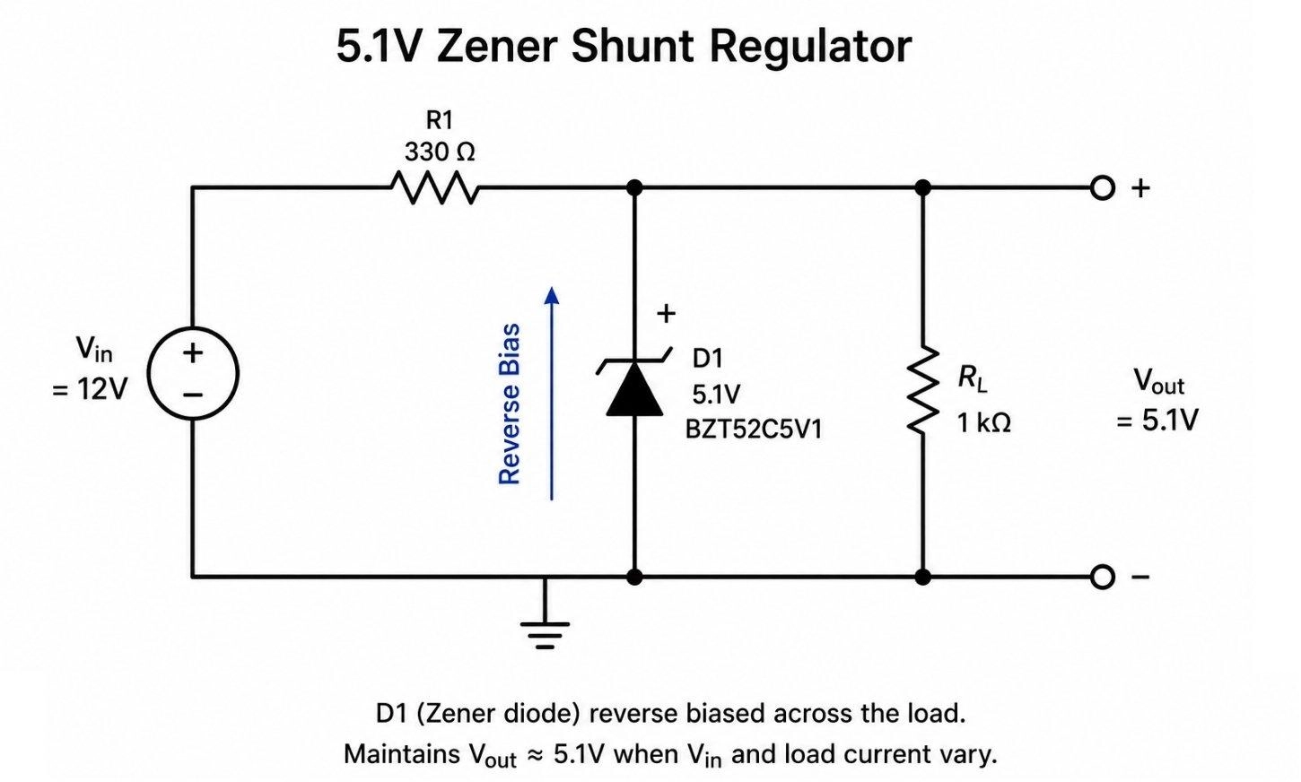
Figure: Zener diode shunt voltage regulator circuit showing 5.1V regulatio
#4 TVS Diodes (Transient Voltage Suppression)
TVS diodes are arguably the most underappreciated component in modern PCB design, and the most commonly misapplied. They are the primary line of defense against ESD events, surge transients, and voltage spikes that destroy downstream ICs.
Key characteristics:
- Response time: Sub-nanosecond (picosecond range for ESD)
- Available unidirectional (one polarity) and bidirectional (for AC or data lines)
- Rated by standoff voltage (Vs), clamping voltage (Vc), and peak pulse power (Ppk)
- IEC 61000-4-2 ESD compliance: ±8kV contact, ±15kV air discharge
Typical applications:
- USB-C and USB 3.x data line protection
- HDMI and Ethernet interface protection
- CAN bus and RS-485 transceiver protection
- Automotive ECU input rail protection (load dump: up to 45V on 12V rail)
- Industrial I/O: relay contact transients, motor back-EMF
PCB Placement Considerations
TVS placement is not optional; it is the difference between working protection and false protection. Always route the protected signal through the TVS before it reaches anything else on the board.
Why Placement Distance Matters
A TVS placed 15mm from a connector offers significantly less protection than one placed 2mm from the pin. The parasitic inductance of even 10mm of trace at ESD frequencies (rise times of ~1ns) is enough to allow a destructive spike past the device before the TVS can fully clamp the voltage.
Unidirectional vs. Bidirectional
- Unidirectional: for DC rails and single-polarity signals (e.g., power lines, GPIO)
- Bidirectional: for AC, differential pairs, and data lines where both polarities occur (USB, HDMI, CAN)
Popular parts: SMAJ5.0A (SMA, unidirectional, 5V), SMBJ12CA (SMB, bidirectional, 12V), ESD9B5V0S (SOD-923, ultra-low capacitance for high-speed lines)
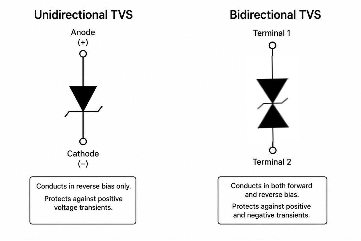
Figure: Circuit symbols for unidirectional and bidirectional TVS diodes with labels
#5 LEDs (Light Emitting Diodes)
LEDs operate on the same P-N junction principle, but are built from compound semiconductors (GaAs, GaN, InGaN) that emit photons during recombination. The emission wavelength, and therefore color, depends on the semiconductor material's bandgap. Just like capacitors require orientation care, understanding SMD LED polarity is crucial during assembly.
Forward voltage by color:
- Infrared: ~1.2-1.5V
- Red: ~1.8-2.2V
- Yellow/Green: ~2.0-2.4V
- Blue/White: ~3.0-3.5V
- UV: ~3.5-4.0V
PCB design considerations:
- Always use a current-limiting resistor or constant-current driver
- High-power LEDs (>500mW) require thermal pad management, as the thermal resistance from junction to PCB copper matters as much as airflow
- COB (Chip-on-Board) LEDs consolidate multiple dies onto one substrate; they need careful thermal spreading in PCB copper layers
Common SMD packages: 0402, 0603, 0805 (indicator LEDs), 2835, 5050, 3528 (lighting), XPE/XPG (high-power)
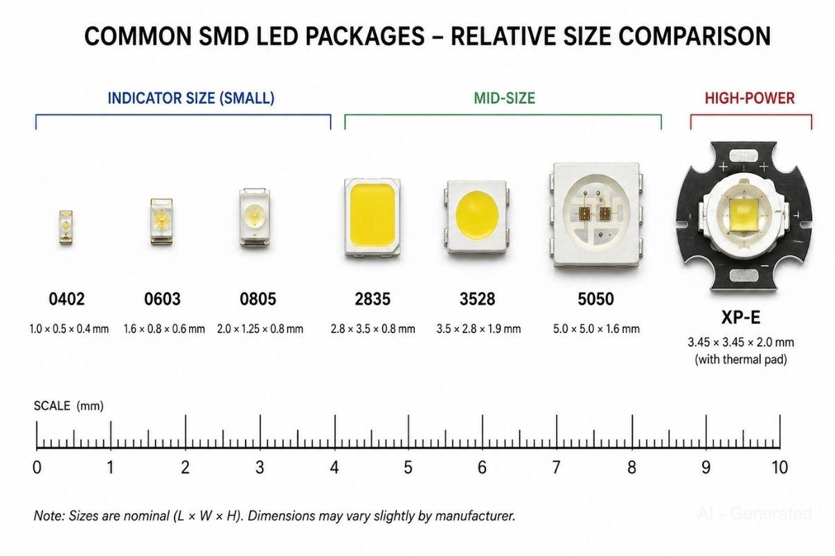
Figure: Comparison of common SMD LED package sizes from 0402 indicator LEDs to high-power XP-E with thermal pad
#6 Fast Recovery and Ultra-Fast Diodes
Standard rectifier diodes can't switch fast enough for modern power electronics. Fast recovery and ultra-fast diodes solve this by reducing reverse recovery time through controlled diffusion processes and platinum or gold doping.
Classification:
- Fast recovery: trr = 100-500ns
- Ultra-fast recovery: trr = 25-100ns
- Hyperfast (some manufacturers): trr < 25ns
In high-voltage EV and industrial power systems, silicon carbide (SiC) Schottky diodes are increasingly replacing traditional ultra-fast recovery devices because they combine high reverse voltage capability with near-zero reverse recovery losses.
Where standard diodes fail, and these do not:
- SMPS secondary rectification at 50-300kHz
- Inverter freewheeling at 10-100kHz
- EV onboard chargers and traction inverters
- Motor drive circuits
Key tradeoff vs. Standard Schottky: Fast recovery diodes handle higher reverse voltages (up to 1200V) and lower leakage at temperature, making them better for high-voltage SMPS rails where standard silicon Schottky devices aren't viable.
Popular parts: UF4007 (DO-41, 1A/1000V, 75ns), MUR860 (TO-220, 8A/600V), STTH8R06 (TO-220, 8A/600V, ultrafast)
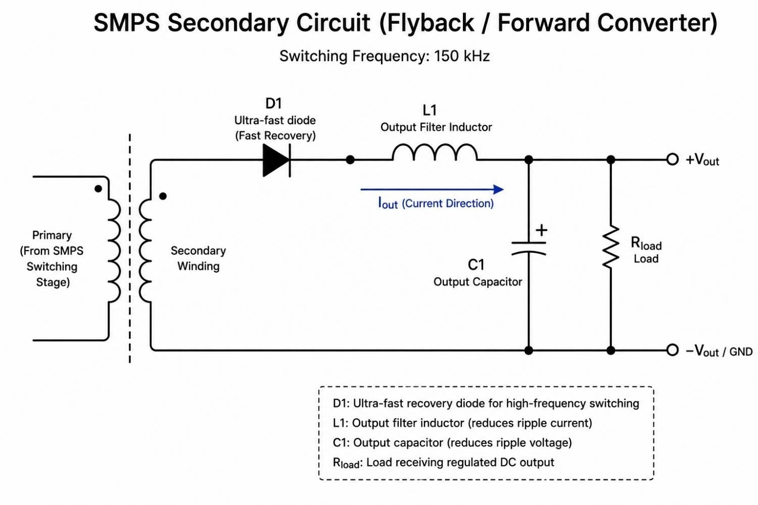
Figure: SMPS secondary rectification circuit using an ultra-fast recovery diode with output filter inductor and capacitor
#7 Photodiodes
A photodiode is a P-N junction optimized for light detection. When photons strike the depletion region, they generate electron-hole pairs, producing a photocurrent proportional to incident light intensity.
Operating modes:
- Photoconductive (reverse-biased): Faster response, lower noise, used in high-speed optical receivers
- Photovoltaic (zero-bias): Used in precision measurement and solar cells; lower dark current
Applications:
- IR receivers (remote controls, IRDA)
- Ambient light sensors
- Medical pulse oximeters
- Optical encoders in motors
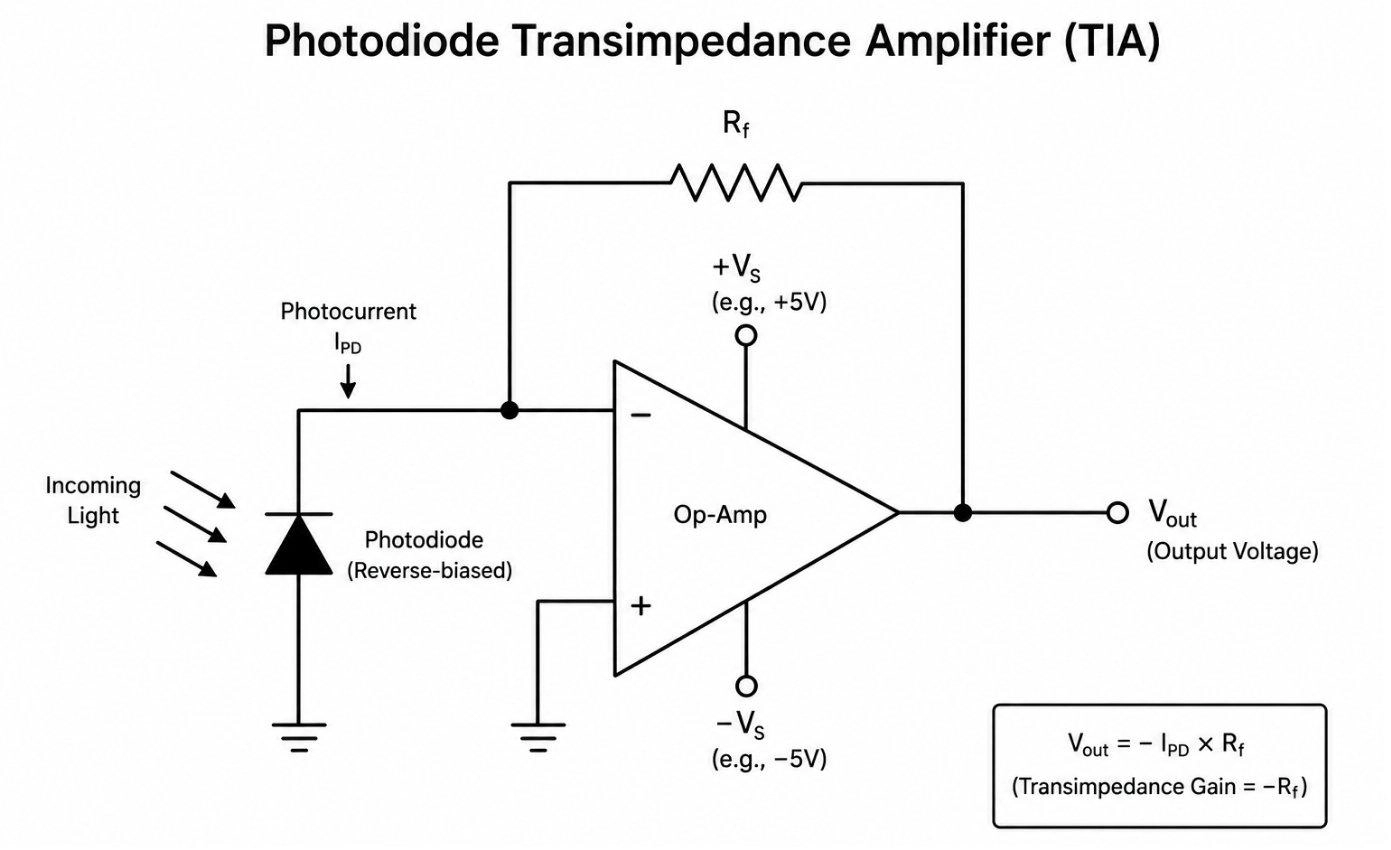
Figue: Photodiode transimpedance amplifier circuit converting light-induced photocurrent to output voltage
#8 Laser Diodes
Laser diodes are electrically similar to LEDs but produce coherent, collimated light through stimulated emission. They require precise drive current control, since exceeding the threshold current even briefly can cause permanent damage.
Applications:
- Fiber optic transceivers (SFP, QSFP modules)
- LiDAR sensors in autonomous vehicles
- Industrial barcode and QR scanners
- Optical storage (legacy CD/DVD/Blu-ray)
How to Choose the Right Diode for Your Circuit
This diode selection guide follows a logical hierarchy. By starting with strict circuit demands and narrowing down based on thermal and packaging constraints, you can avoid unexpected failures in the field.
Step 1 - Define voltage requirements
- What is the maximum reverse voltage the diode will see, including transients?
- Apply a safety derating of 50-70%: if your rail is 48V, don't use a 50V diode, use an 80V or 100V rated part.
Step 2 - Define current requirements
- Average forward current (IF(avg)) under normal operation.
- Peak repetitive current during switching.
- Surge current during startup or fault conditions.
Step 3 - Determine switching frequency
- Below 1kHz: Standard rectifier diode is fine.
- 1kHz-100kHz: Fast recovery or Schottky required.
- Above 100kHz: Schottky strongly preferred; ultra-fast if voltage demands it.
Step 4 - Evaluate power dissipation
- Pd = Vf ✖ IF - this tells you how much heat the diode generates.
- Check the package's θJA (thermal resistance) and ensure junction temperature stays below 125°C (150°C absolute max for most silicon).
Step 5 - Consider the environment and leakage
- High temperature environments (>85°C) amplify Schottky leakage, which may favor fast recovery diodes instead.
- Battery-powered systems need low reverse leakage - check IR spec at operating temperature.
Step 6 - Select package
- Match to assembly method (SMT vs through-hole).
- Verify thermal footprint supports the Pd calculated in Step 4.
- Confirm footprint availability in your PCB library.
Quick Reference: Application to Diode Type
| Application | Recommended Diode | Example Part |
|---|---|---|
| 50Hz mains rectifier | Rectifier (1N400x / M7) | 1N4007, M7 |
| Buck/boost converter output | Schottky | SS34, MBRS360 |
| USB-C / interface ESD protection | TVS (low capacitance) | ESD9B5V0S, PRTR5V0U2X |
| 5V logic reference | Zener | BZT52C5V1 |
| SMPS at 150kHz, high voltage rail | Ultra-fast recovery | UF4007, STTH8R06 |
| RF signal detection | Low-capacitance Schottky | BAT54, HSMS-2850 |
| Automotive reverse polarity protection | Schottky or P-FET | MBRF20100CT |
| Industrial I/O surge protection | TVS (high power) | SMBJ18CA |
Note
Part numbers shown are representative; always verify specifications against your exact design conditions.
Common Mistakes When Selecting Diode Types
These are real design errors that appear in PCB reviews, and they're all avoidable.
1. Ignoring reverse recovery in switching circuits: Using a 1N4007 in a 100kHz buck converter is one of the most common beginner mistakes. The diode will overheat and potentially fail within hours at full load.
2. Choosing insufficient reverse voltage: Derating is not optional. A diode rated exactly at the rail voltage will fail under load transients, especially in inductive circuits where flyback voltages can spike 3-5× the supply.
3. Underestimating surge current: Startup and fault events can push 10-50× steady-state current through a diode for microseconds. Check the IFSM (non-repetitive surge current) spec, not just IF.
4. Ignoring thermal design for SMD diodes: A SOD-123 Zener rated at 500mW can only dissipate that power with a proper copper pour. On a 1oz copper island with no pour, real-world dissipation may be 150mW before hitting temperature limits. Reviewing best practices for solder pad design is critical for thermal management.
5. Placing TVS diodes too far from the connector: A TVS on the far side of a PCB from the input connector provides minimal protection. The parasitic inductance of even 10mm of trace is enough to allow a destructive voltage spike past the device during a fast ESD event.
6. Using unidirectional TVS on a data line: Data lines carry both polarities. A unidirectional TVS on USB D+ or CAN High will clip the signal and corrupt data. Always use bidirectional TVS on differential or AC-coupled lines.
7. Wrong footprint for the power level: Selecting the SMA package for a 3W dissipation application without checking the thermal resistance math. SMA θJA is typically 50-100°C/W depending on copper area, so do the math before committing to the package.
SMD Diode Types: Useful Engineering Considerations
When selecting SMD diode types, there are several manufacturing and thermal realities to keep in mind:
- SMD packages dissipate heat primarily through PCB copper pours, so always add a thermal relief pad and copper fill for higher-power SMD diodes.
- Through-hole packages have better natural convection; they remain preferred in open-air, high-power designs without forced cooling.
- For D2PAK packages, providing a ground copper pour under the tab is non-negotiable if power dissipation exceeds 5W.
- SMD packages are built for automated pick-and-place and reflow soldering, making them strongly preferred for volume production through JLCPCB SMT assembly.
- SOD-923 and 0402-class packages require precise reflow profiles and excellent paste control; they are notoriously difficult to hand-solder.
- DO-41 through-hole parts remain useful for fast breadboarding, prototyping, and legacy repair.

- Always check the courtyard clearance between SMD diodes and adjacent components. SMA and SMB packages are surprisingly bulky and frequently cause Design Rule Check (DRC) violations in dense layouts.
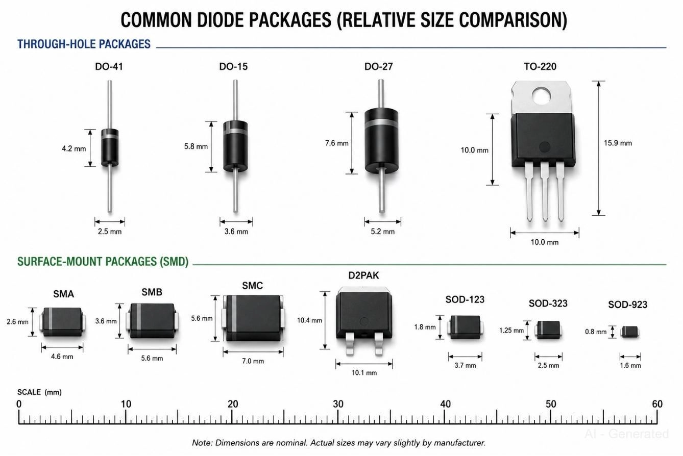
Figure: Size comparison of common through-hole and SMD diode packages from DO-41 and TO-220 to SMA, SMB, SMC, D2PAK, and SOD-series
Through-Hole vs SMD Diode Packages
Choosing between various diode packages is not just a footprint decision, as it fundamentally dictates your thermal performance, assembly method, and current handling limits.
Diode Package Comparison Table
Common diode package types and their SMD equivalents. Package size directly affects thermal resistance and current handling capability.
| Through-Hole | SMD Equivalent | Max Current (typical) | Assembly |
|---|---|---|---|
| DO-41 (axial) | SMA (DO-214AC) | 1-3A | Manual / Reflow |
| DO-15 (axial) | SMB (DO-214AA) | 2-5A | Reflow |
| DO-27 (axial) | SMC (DO-214AB) | 3-10A | Reflow |
| TO-220 | D2PAK (TO-263) | 5-30A | Reflow / Press-fit |
| SOD-123 | N/A | 200mA-1A | Reflow |
| SOD-323 | N/A | 100-300mA | Reflow |
| SOD-923 | N/A | 100mA | Reflow (ultra-compact) |
Why Diode Selection Matters in Modern Electronics
A compact GaN charger can fail from a single poorly chosen diode. In high-frequency power electronics, selecting the correct device is a practical engineering skill, not just textbook knowledge.
Modern PCB design demands more from diodes than ever before:
- GaN and SiC power supplies switch at MHz frequencies, where standard diodes simply can't keep up
- USB-C PD circuits carry up to 240W and need tight overvoltage and ESD protection
- Automotive ECUs face load dump transients exceeding 40V on a nominal 12V rail
- IoT and wearable devices push for ultra-compact SMD packages without sacrificing thermal performance
- SMPS designs live or die by reverse recovery characteristics
To help you navigate these choices and avoid common pitfalls, this article explores the essential characteristics that separate a robust design from one that fails in the field.
What Is a Diode and How Does It Work?
At its core, a diode is a two-terminal semiconductor device that allows current to flow in one direction and blocks it in the other.
P-N Junction Basics
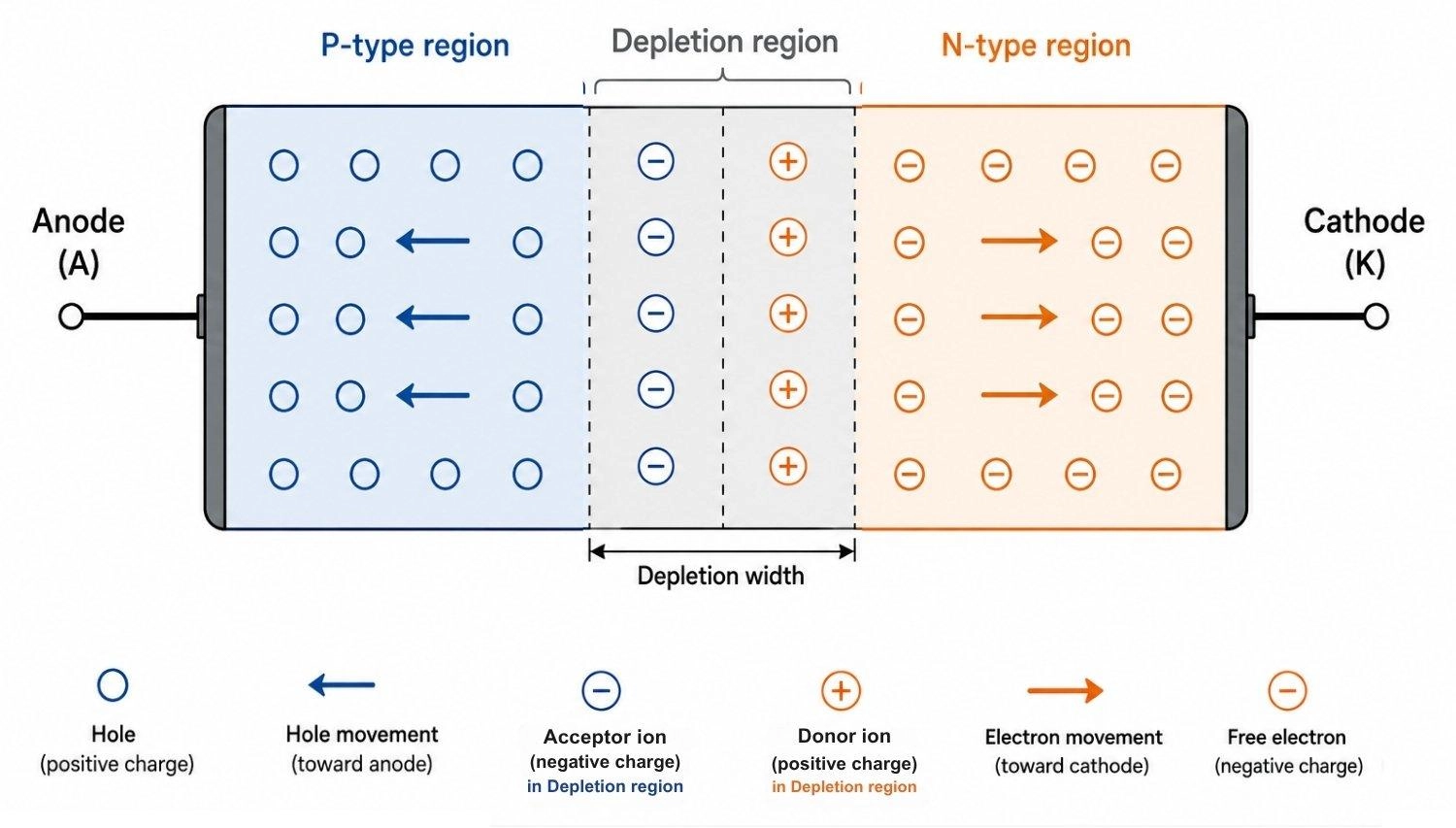
Figure: A P-N junction diode showing P-type and N-type regions, depletion region, and carrier movement direction
A standard diode is built from a P-N junction, which is a boundary between a P-type semiconductor (holes as majority carriers) and an N-type semiconductor (electrons as majority carriers). At the junction, carriers recombine and create a depletion region with a built-in electric field.
- Forward bias: Applying a positive voltage to the anode collapses the depletion region, and current flows once the threshold voltage is overcome (~0.6-0.7V for silicon)
- Reverse bias: Polarity reverses the field, widens the depletion region, and only a tiny leakage current flows until the breakdown voltage is reached
Common Diode Symbols in Schematics
Every diode type has a distinct schematic symbol. Recognizing diode symbols quickly is essential for reading datasheets, application notes, and reference designs. If you are reviewing symbols, you might also find our comprehensive diode symbol guide helpful for catching the subtle differences between variants.
These symbols appear consistently across IEC and ANSI standards, and most PCB EDA tools (KiCad, Altium, EasyEDA) include all variants in their standard libraries.
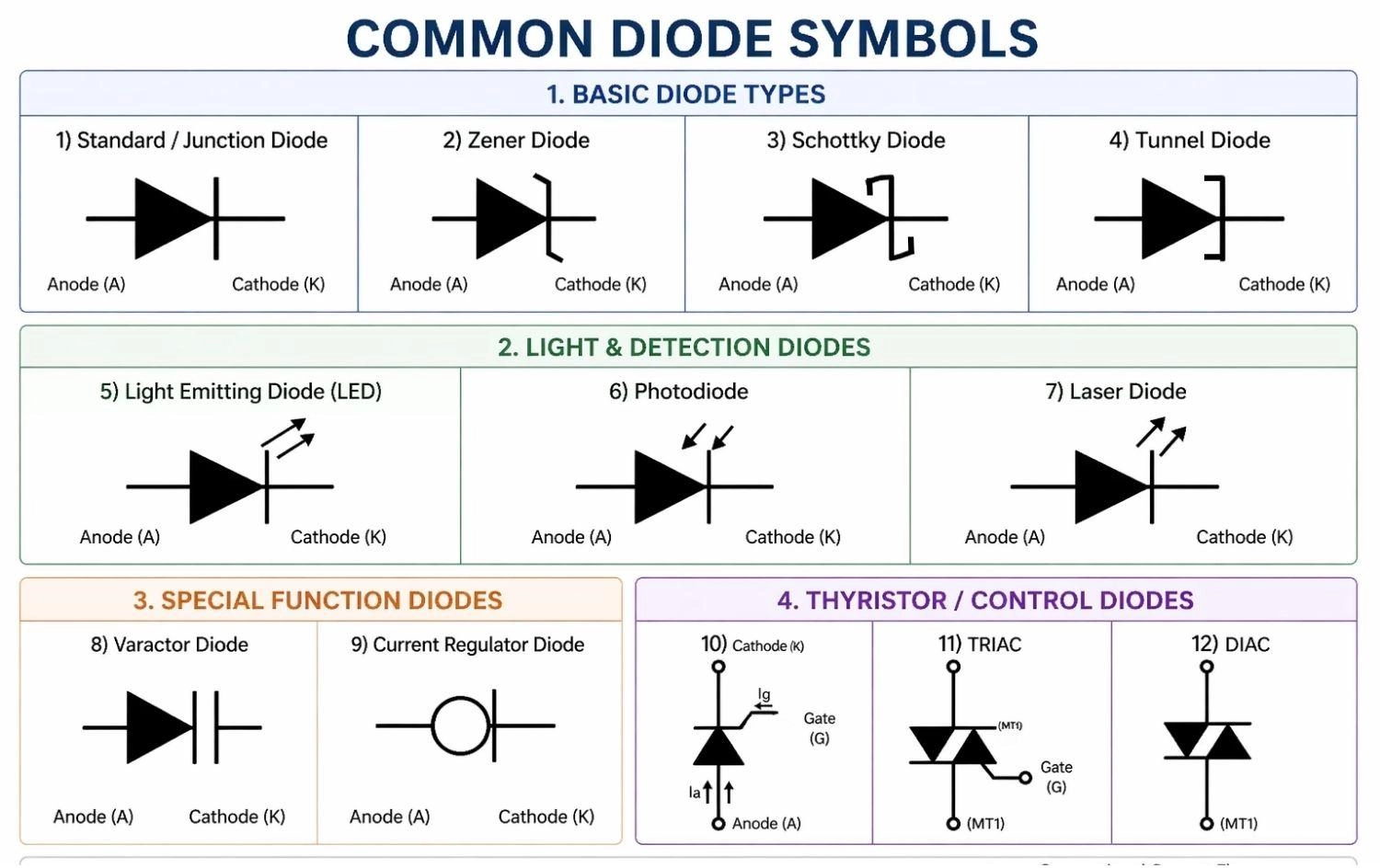
Figure: The schematic symbols for Standard (Junction), Zener, LED, Schottky, Photodiode, Tunnel, Varactor, Current Regulator, SCR, DIAC, and TRIAC Diodes.
Key Diode Parameters Engineers Must Understand
Before selecting a diode from a distributor or the JLCPCB Parts Library, engineers should carefully review the key electrical parameters in the datasheet. These values determine switching performance, thermal behavior, voltage tolerance, and long-term circuit reliability.
| Parameter | What It Means | Why It Matters |
|---|---|---|
| Forward Voltage (Vf) | Voltage drop when conducting | Directly affects power loss and heat |
| Reverse Voltage (VRRM) | Max reverse blocking voltage | Undersizing causes catastrophic failure |
| Reverse Leakage (IR) | Current in reverse bias | Critical in low-power battery circuits |
| Reverse Recovery Time (trr) | Time to switch off from forward conduction | Determines usable switching frequency |
| Junction Capacitance (Cj) | Parasitic capacitance across the junction | Affects RF and high-frequency performance |
| Power Dissipation (Pd) | Max heat the package can handle | Drives thermal design and derating |
| Switching Speed | Overall AC performance | Key for SMPS, motor drives, inverters. |
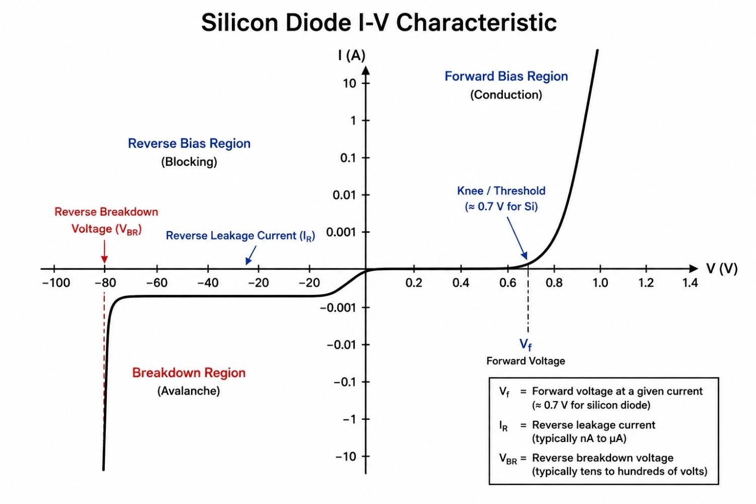
Figure: Diode I-V characteristic curve showing forward knee voltage, reverse leakage, and reverse breakdown region
Reverse Recovery: The Parameter Most Designers Overlook
Reverse recovery time (trr) is the time a diode takes to stop conducting after forward current stops. During this window, the diode briefly conducts in the wrong direction, a phenomenon called reverse recovery current.
- In 50Hz rectifiers: negligible, doesn't matter
- In 100kHz SMPS: causes significant switching loss, heat, and EMI
- In 1MHz+ converters: standard diodes are simply unusable
FAQs on Diode Types
Q: What Are the Main Types of Diodes?
The most common diode types include rectifier diodes, Zener diodes, Schottky diodes, LEDs, photodiodes, and TVS diodes, each designed for specific electrical functions.
Q: What happens if a diode’s reverse voltage rating is too low?
If the reverse voltage exceeds the diode’s rating, the junction can enter avalanche breakdown and permanently fail. Engineers typically derate reverse voltage by 50–70% in real designs.
Q: Why are Schottky diodes faster than standard P-N diodes?
Schottky diodes use a metal-semiconductor junction and do not store minority carriers, giving them near-zero reverse recovery time for high-frequency switching circuits.
Q: Can a 1N4007 diode be used in a switching power supply?
Not effective at high frequency. The 1N4007 has microsecond-level reverse recovery time, which creates switching losses and heat in SMPS circuits.
Q: Why are TVS diodes placed close to connectors on PCBs?
Even a short PCB trace adds parasitic inductance during fast ESD events. Placing the TVS near the connector improves surge clamping before spikes reach sensitive ICs.
Q: What causes thermal runaway in Schottky diodes?
As junction temperature rises, reverse leakage current increases rapidly, generating more heat and potentially causing uncontrolled temperature escalation.
Q: Why are SiC diodes becoming popular in EV power electronics?
Silicon carbide diodes combine high reverse-voltage capability with extremely low reverse recovery loss, improving efficiency in high-voltage inverters and chargers.
Conclusion
Selecting the right diode is no longer just about voltage and current ratings. In modern PCB design, switching speed, thermal behavior, package type, and transient protection all directly affect reliability and efficiency.
Whether you're designing a USB-C power stage, an automotive controller, or a compact IoT device, understanding the strengths and tradeoffs of each diode family helps prevent costly design mistakes.
When you are ready for production, JLCPCB provides seamless, high-quality PCB assembly tailored to your needs. Check your budget instantly on the JLCPCB quotation page and bring your electronic designs to life.
Popular Articles
• SMD Diode Code Lookup: Full List, Marking Guide & Identification [2026 Guide]
• SMD Resistor Package Sizes: Complete Size Chart, Footprints & How to Choose
• SMD Capacitor Codes: Identification, Markings, and Polarity
• SMD Capacitor Sizes: Complete Size Chart and Selection Tips for PCB Design and Assembly
• How to Solder SMD Components Like a Pro [2026 Updated]
Keep Learning
PoP Package (Package on Package) Explained: Architecture, Assembly, and SMT Challenges
In the race for miniaturization, fitting more processing power into smaller footprints is the ultimate challenge for PCB designers. Package on Package (PoP) technology answers this by integrating logic and memory vertically, becoming the standard for modern mobile processors. However, this 3D architecture demands advanced SMT assembly capabilities beyond standard fabrication. JLCPCB specializes in the high-precision manufacturing required to master these complex stacks. This guide covers how PoP packa......
What Is a PQFP Package? Plastic Quad Flat Package Design, Footprint, and Assembly Guide
The Plastic Quad Flat Package (PQFP) is a widely used IC package in industrial, automotive, and embedded designs. This article provides a practical, engineering-focused guide to PQFP package. It explains how PQFP is built, when it makes sense to use it, how it compares with newer package types, and what designers should consider in terms of footprint design, thermal performance, signal integrity, manufacturing, and reliability. What Is a PQFP Package (Plastic Quad Flat Package)? A Plastic Quad Flat Pa......
Small Outline Integrated Circuit (SOIC): Package, Specs & Uses
As designs transition from legacy through-hole components to high-density Surface Mount Technology (SMT), the Small Outline Integrated Circuit (SOIC) remains the industry standard for operational amplifiers, flash memory, sensors, and microcontrollers. It stands as a testament to balanced engineering, offering a perfect compromise between the miniaturisation demanded by modern consumer electronics and the ruggedness required for industrial applications. This article serves as a definitive engineering ......
A Complete Guide to Surface Mount Device (SMD)
Imagine holding a smartphone in your hand. Inside that sleek device lies a complex network of thousands of miniature components — resistors smaller than a grain of rice, capacitors thinner than a fingernail, and integrated circuits containing millions of transistors. Without Surface Mount Technology (SMT) and its compact Surface Mount Devices (SMDs), none of this would exist. Just a few decades ago, electronics were bulky. Radios filled desks, computers filled rooms, and assembling a circuit meant dri......
Circuit Breaker Types Explained: MCB, MCCB, RCCB, RCBO, ACB, VCB & SF6 Circuit Breakers
A circuit breaker automatically disconnects power when it detects faults such as overloads or short circuits, protecting equipment and reducing fire risk. Different circuit breaker types are designed for different voltage levels, current ratings, and applications, from household distribution boards to high-voltage substations. This guide explains the most common types - including MCBs, MCCBs, RCCBs, RCBOs, ACBs, VCBs, and SF6 breakers and helps you choose the right one for your application. Figure: Ci......
Quad Flat Package (QFP): The Engineer's Guide to Design, Assembly and Thermal Management
What is QFP Package? The Quad Flat Package (QFP) is one of the most popular surface mount technology (SMT) package formats throughout the history of electronic manufacturing. After it became standard in the 1980s, the QFP has been the industry standard for integrated circuits (ICs) with moderate to high pin counts that typically range from 32 to 304 pins, so it was a good alternative for simple SOIC packages and complex Ball Grid Arrays (BGAs) at the same time. Defined by its "gull-wing" leads extendi......