
SMD Inductor Selection Guide: How to Choose the Right Inductor for Any Circuit
16 min
- SMD Inductor Selection Cheat Sheet
- Step-by-Step SMD Inductor Selection Workflow
- How to Choose an SMD Inductor Based on Application
- SMD Inductor Selection Examples (Real-World Use Cases)
- SMD Inductor Selection Mistakes to Avoid
- SMD Inductor Types and Applications
- Key SMD Inductor Specifications Explained
- What Is an SMD Inductor?
- How SMD Inductors Work: Core Principles Explained
- Common SMD Inductor Problems and How to Fix Them
- SMD Inductor vs Through-Hole Inductor: Key Differences
- FAQ about SMD Inductor
- Conclusion
Choosing the wrong SMD inductor can quietly destroy your design - causing overheating, efficiency loss, noise, or even complete circuit failure. Yet most selection mistakes come from misunderstanding just a few key parameters.
This guide cuts through the confusion and shows you exactly how to select the right SMD inductor with confidence.
In this guide, you will learn:
SMD Inductor Selection Cheat Sheet
A rapid-reference cheat sheet for engineers when choosing SMD inductors.
Keep this table handy when reviewing BOMs or doing schematic capture.
Parameter | Ideal Rule of Thumb | Risk of Ignoring |
|---|---|---|
Inductance (L) | Match the IC datasheet calculation. | Instability, excessive voltage ripple. |
Isat (Saturation) | Isat > Peak Current + 30%. | Core saturation, IC destruction. |
Irms (Thermal) | Irms > Continuous Load + 20%. | Severe overheating, PCB damage. |
DCR (Resistance) | As low as the budget/size allows. | Poor efficiency, excessive heat. |
SRF (Frequency) | SRF > 10x Operating Frequency. | An inductor acts like a capacitor, but fails to filter. |
Step-by-Step SMD Inductor Selection Workflow
If you are wondering how to choose an SMD inductor step by step, follow this foolproof workflow for any circuit.
Step 1: Define Circuit Requirements
Define your maximum continuous current, peak transient current, and operating frequency right away.
Step 2: Choose Inductance Value
Calculate the required µH using the IC datasheet to aim for a ripple current that is 20% to 40% of your maximum output current.
Step 3: Estimate Current Ratings
Calculate the absolute peak current (Load Current + Half of Ripple Current) to determine your Isat requirements.
Step 4: Check DCR and Efficiency
Look at the datasheets and pick the inductor with the lowest DCR to minimize I²R heat losses.
Step 5: Select Package and Verify Layout
Ensure the physical footprint fits your PCB and provides adequate copper pouring around pads for heat dissipation.
Step 6: Verify Self-Resonant Frequency (SRF)
Ensure the inductor's SRF is well above the operating frequency to maintain inductive behavior and avoid performance degradation.
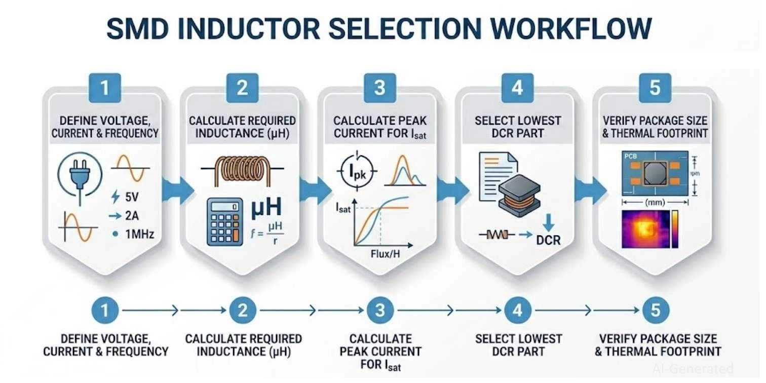
Figure: Step-by-step guide for SMD inductor selection
How to Choose an SMD Inductor Based on Application
Different applications impose completely different electrical and thermal constraints on SMD inductors. Here is how to choose an SMD inductor based on its job.
Selecting an SMD Inductor for Power Circuits (DC-DC Converters)
In power regulators, efficiency and safety are paramount. Your priority is ensuring Isat exceeds your peak switching current and minimizing DCR to prevent heat generation.
Selecting an SMD Inductor for RF Circuits
In radio frequency designs, current is usually tiny. Here, SRF (Self-Resonant Frequency) is the most critical parameter to minimize signal loss.
Selecting an SMD Inductor for EMI Filtering
When acting as a choke to block noise, the inductor needs high impedance at the specific frequency of the noise. Shielding is vital.
Selecting an SMD Inductor for General Signal Applications
For basic analog signal smoothing, you balance stability against board size. Standard unshielded ferrite inductors often suffice.
Application | Priority Parameter | Secondary Focus |
|---|---|---|
Power (DC-DC) | Current (Isat/Irms) & Low DCR | Shielding for EMI |
RF / Wireless | High SRF & Q-Factor | Tight tolerance |
EMI Filtering | Impedance at noise frequency | Shielding |
Pro Tip for Designers:
In practical PCB design, correct component selection must be paired with reliable manufacturing. Platforms like JLCPCB ensure stable SMT assembly and consistent component quality, which directly affects inductor performance in real circuits.
SMD Inductor Selection Examples (Real-World Use Cases)
These real-world examples show how selection changes based on application.
Power Supply Example
Scenario: 12V to 5V buck converter supplying 3A continuous.
Selection: A 4.7µH shielded ferrite power inductor.
Why: Requires Irms > 3.6A and Isat > 4.5A. A 6x6mm package ensures ultra-low DCR (<20mΩ).
RF Circuit Example
Scenario: 2.4GHz Bluetooth module matching network.
Selection: A 2.2nH 0402 multilayer ceramic RF inductor.
Why: Current is negligible. Focus is on ±5% tolerance and an SRF well above 6GHz.
EMI Filtering Example
Scenario: Suppressing 10MHz motor noise on a 24V power rail.
Selection: An EMI Choke/Filter inductor.
Why: Target maximum AC impedance specifically at the 10MHz noise band.
SMD Inductor Selection Mistakes to Avoid
Avoid these common inductor selection mistakes to ensure your prototypes work on the first iteration.
Blindly copying an inductor from an old schematic without recalculating for a new switching frequency will result in severe instability or massive voltage ripple.
Never pick an Isat rating that exactly matches your load. Always leave a 20% to 30% headroom.
Focusing only on inductance and ignoring DCR is a recipe for battery drain. High DCR kills efficiency in portable electronics.
Trying to cram a 5A power path through a tiny 0805 inductor will result in a blown component. Physics cannot be cheated; high current requires a larger physical wire and core mass.
SMD Inductor Types and Applications
Before looking at specifications, it is crucial to understand that not all inductors are built the same. Selecting the correct type is the first step in successful circuit design.
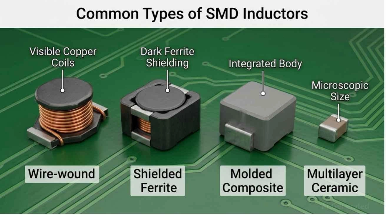
Figure: Three common SMD inductor types: Wire-wound, Molded Composite, and Multilayer ceramic inductors.
Type | Best For | Key Feature |
|---|---|---|
Power Inductor | DC-DC Converters | High Isat, Low DCR |
RF Inductor | Wireless / Antennas | High SRF, Tight Tolerance |
Molded (Composite) | Low-noise, Automotive | Eliminates whining, soft saturation |
Multilayer | High-density signal lines | Micro-sized, Cost-effective |
Wire-Wound | General power/filtering | Higher current capacity |
Shielded | Dense PCBs, EMI sensitive | Contains magnetic flux, prevents noise |
Unshielded | Budget designs, space focus | Higher current for size, radiates EMI |
Power Inductors (High Current Applications)
Designed with thick windings and large magnetic cores to handle high currents without saturating.
Best for: Buck/boost regulators and power management ICs (PMICs).
RF Inductors (High-Frequency Circuits)
Prioritizes high self-resonant frequencies (SRF) and tight tolerances over current capacity.
Best for: Antenna impedance matching and RF communication modules.
Molded (Composite) SMD Inductors
Manufactured by pressing magnetic iron powder directly around the coil to eliminate acoustic whining and provide soft-saturation characteristics.
Best for: Automotive systems, low-noise supplies, and high-current PMICs.
Multilayer vs Wire-Wound SMD Inductors
Wire-wound: Use real copper wire wrapped around a core for superior current handling and low DCR.
Multilayer: Layered ceramic/ferrite sheets that are ultra-compact and cost-effective for low-current signal lines.
Shielded vs Unshielded Inductors
Shielded inductors contain magnetic flux to prevent EMI leakage in dense boards. Unshielded versions are cheaper and handle slightly more current, but radiate noise that interferes with sensitive traces.
Key SMD Inductor Specifications Explained
These parameters are directly taken from inductor datasheets and determine real-world performance. This is the most critical phase of the inductor selection guide. Misunderstanding these parameters guarantees hardware failure.
#1 Inductance Value (µH) - How It Affects Circuit Behavior
Measured in microhenries (µH) or nanohenries (nH), this dictates energy storage capacity. As a rule, your choice trades transient response speed against ripple current amplitude (lower inductance = faster response but higher ripple).
Quick Formula (Conceptual):
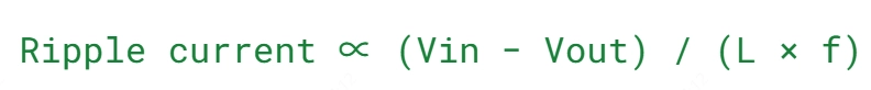
Design Tip: Use higher inductance only if ripple is a primary concern; otherwise, lower inductance improves transient response.
#2 Current Rating of Inductor - Saturation vs RMS Explained Clearly
Confusing saturation current vs rms current is the #1 mistake designers make.
Saturation Current (Isat): The point where the magnetic core is "full." If exceeded, inductance drops drastically, causing a massive current spike.
RMS Current (Irms): The thermal limit. This is the continuous current the inductor can handle before it overheats.
Design Tip: Never operate a high current SMD inductor at its absolute limit; always leave a 20–30% safety margin for Isat and Irms.
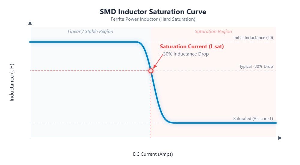
Figure: Inductance vs. DC-current graph showing an SMD inductor's hard saturation curve dropping 20-30% at the Isat limit.
#3 DC Resistance (DCR) in Inductor- Efficiency and Thermal Loss
DCR in an inductor is the physical resistance of the internal copper wire. It is the primary cause of inductor efficiency loss.
I²R Loss: Power lost as heat equals Current squared multiplied by DCR.
Thermal Impact: Sourcing high-quality components from the JLCPCB Electronic Parts Library lets you filter inductors by ultra-low DCR to maximize battery life.
Design Tip: Always compare multiple vendors to achieve a lower DCR at the same package size to maximize power efficiency.
#4 Self-Resonant Frequency (SRF) of Inductor - High-Frequency Limits
Every inductor has tiny parasitic capacitances between its coil windings. Above the SRF, the inductor stops acting like an inductor and starts acting like a capacitor.
Design Tip: For RF applications, ensure your operating frequency is at least 10x lower than the inductor's listed SRF.
#5 Inductor Core Material - Ferrite vs Iron Powder
Ferrite Cores: Excellent for high frequencies, very low core losses, but they suffer from a sharp, sudden saturation curve.
Iron Powder Cores: Better at handling massive currents and feature a "soft" saturation curve.
Design Tip: Choose powdered iron or composite cores for high-current power supplies to benefit from their gentle saturation drop-off.
#6 Shielding of Inductor - EMI Performance Considerations
Unshielded Inductors: Cheaper and handle slightly more current for their size, but radiate magnetic flux.
Shielded Inductors: Encased in a magnetic shield that contains the flux. Mandatory for dense PCBs.
Design Tip: Default to shielded inductors in dense, mixed-signal boards to prevent unexpected EMI headaches.
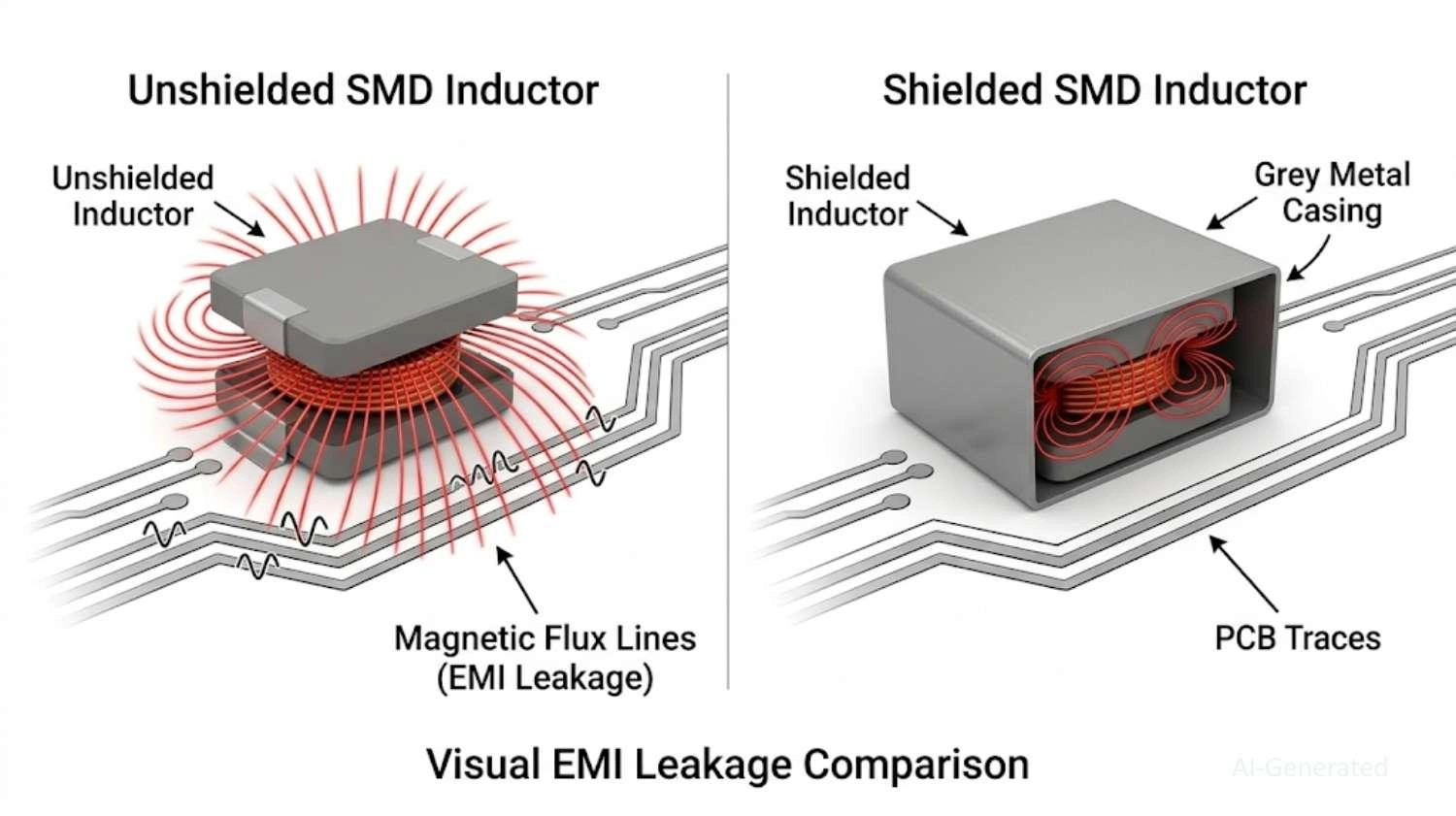
Figure: EMI leakage comparison between shielded and unshielded SMD inductors, showing magnetic flux lines escaping the unshielded version.
#7 SMD Inductor Package - Current vs Footprint Trade-Off
Selecting the right SMD inductor package requires balancing current handling capability with available PCB space. In general, larger package sizes provide higher saturation current (Isat), higher RMS current ratings (Irms), and lower DCR due to thicker windings and improved thermal performance.
However, this relationship is not absolute and depends on core material, construction, and operating frequency. Larger packages also increase cost and consume more board space, making them less suitable for compact designs.
Design Tip: If an SMD inductor is overheating, consider upgrading to a larger package size, which typically improves heat dissipation and current handling. Also, verify PCB layout, copper area, and airflow, as thermal issues are often influenced by multiple factors.
#8 SMD Inductor Package Size - Current vs Footprint Trade-Off
When reviewing an SMD inductor size chart (comparing standard metric footprints like 0603 vs. large 6x6mm blocks), remember that a larger physical package generally equates to higher current capacity and lower DCR.
Design Tip: If your inductor is overheating, upgrading to a larger footprint (which allows thicker internal wire) is often the easiest fix
#9 Inductor Tolerance and Temperature Stability
Inductance tolerance (e.g., ±20%) means a 10µH inductor could actually be anywhere from 8µH to 12µH.
Design Tip: Power regulators can usually tolerate ±20%, but RF matching networks require tight ±5% or ±2% tolerances.
What Is an SMD Inductor?
An SMD (Surface Mount Device) inductor is a passive electronic component designed to store energy in a magnetic field when an electric current flows through it. Unlike older through-hole components, SMD inductors are optimized for automated assembly and high-density boards.
What Does an SMD Inductor Do in a Circuit?
At a fundamental level, an SMD inductor's function revolves around three main tasks:
- Energy storage: Storing magnetic energy during switching cycles (crucial for power converters).
- Filtering noise: Blocking high-frequency AC noise while allowing DC to pass.
- Current smoothing: Resisting sudden changes in current, acting as a buffer for sensitive ICs.
Internal Structure of an SMD Inductor
To understand how to choose an SMD inductor, you must understand what's inside it:
- Copper winding: The conductive coil where current flows. Thicker wire lowers resistance but increases size.
- Magnetic core: Usually made of ferrite or iron powder, this concentrates the magnetic flux to increase the inductance value.
- Encapsulation: The outer resin or molding that protects the coil and provides a flat surface for pick-and-place machines.
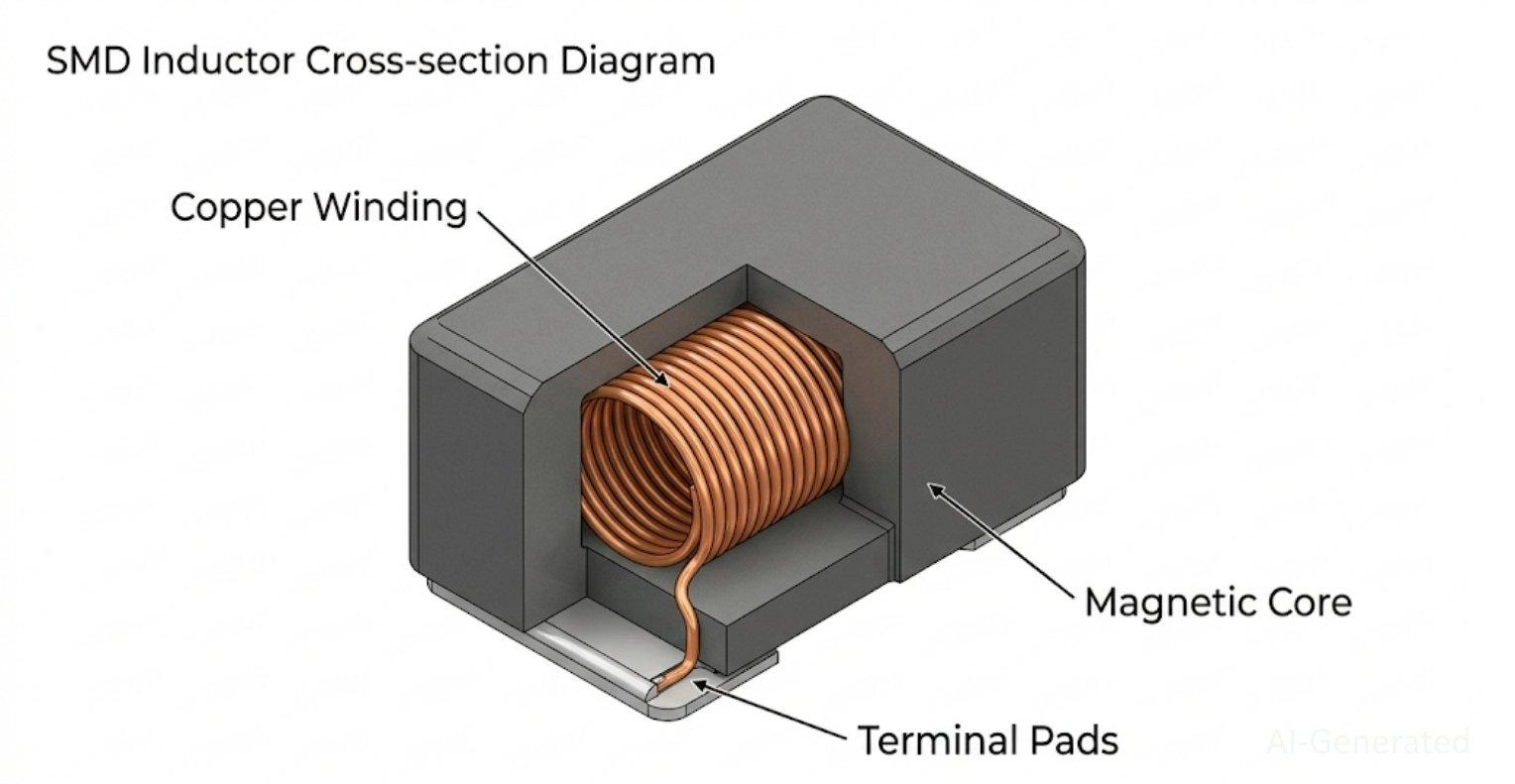
Figure: An SMD inductor revealing the internal copper wire coil, magnetic ferrite core, outer shielding, and metal terminal pads.
Reading SMD Inductor Markings
To identify a component already on a PCB, you must decode the SMD inductor markings printed on the top casing. Most larger inductors use a standard 3-digit SMD inductor code (e.g., "470" = 47µH, "101" = 100µH), similar to how surface mount resistors are labeled.
Common Applications of SMD Inductors in Electronics
How SMD Inductors Work: Core Principles Explained
Understanding the SMD inductor working principle makes component selection much more intuitive.
Magnetic Energy Storage and Current Flow
Current flowing through the coil creates a magnetic field. If current drops, the collapsing field induces a voltage to keep it flowing - aggressively opposing any change in current.
Inductance, Current Change, and Voltage Relationship
Governed by V = L (di/dt), a higher inductance sustains voltage longer against current changes. In power supplies, this specific property dictates the amplitude of your AC ripple current.
Frequency Behavior of Inductors
Inductors act as a short circuit at DC (0 Hz). As frequency rises, their impedance increases, allowing them to pass pure DC power while effectively blocking high-frequency AC noise.
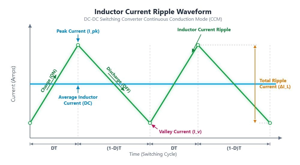
Figure: Inductor current ripple waveform in a DC-DC switching converter, illustrating the continuous charge and discharge cycles.
Common SMD Inductor Problems and How to Fix Them
Even with careful calculation, real-world circuits can act up. Here is how to diagnose common issues.
Problem | Likely Cause | How to Fix |
|---|---|---|
Overheating | High DCR / Exceeded Irms | Larger package, lower DCR |
Audible Whine | Magnetostriction / Core vibration | Use molded/composite core |
Voltage Drop | Excessive DCR | Choose the lower resistance part |
Circuit Shutdown | Core Saturation (Exceeded Isat) | Increase Isat rating |
Inductor Overheating
If your inductor is burning up, your Irms rating is too low, or your DCR is too high. Poor reflow soldering profiles can also increase thermal resistance.
Fix: Upgrade to a larger package size with a higher Irms and lower DCR.
Audible Noise (Whining)
Inductor noise whining happens due to "magnetostriction" - the physical core vibrating at audible frequencies.
Fix: Use a molded composite inductor (which dampens vibration) or adjust your switching frequency.
Voltage Drop and Efficiency Loss
If your output voltage sags under load, your inductor's DCR might be acting as a harsh resistor.
Fix: Select a component with thicker internal windings (lower DCR).
Saturation Issues
If a circuit works fine at 1A but violently fails at 2.5A, the inductor core has likely saturated.
Fix: Choose an inductor with an Isat rating at least 30% higher than your maximum calculated peak current.
Testing for Component Failure
If you suspect a hardware failure, knowing how to test smd inductor with multimeter is a vital diagnostic step. Set the multimeter to continuity or resistance mode; a working inductor should measure very low resistance (close to its DCR), while a blown component will read as an open circuit (infinite resistance).
SMD Inductor vs Through-Hole Inductor: Key Differences
When shifting from breadboards to manufactured PCBs, understanding Surface Mount vs Through-hole constraints is critical. Through-hole technology (THT) inductors are still used, but SMD variants dominate modern design.
Feature | SMD Inductor | Through-Hole Inductor |
|---|---|---|
Size & Density | Highly compact, allowing dense layouts. | Bulky, requires larger board space. |
Assembly | Optimized for automated Pick-and-Place. | Often requires manual insertion/wave soldering. |
Parasitics | Lower parasitic capacitance/inductance. | Higher parasitics due to long wire leads. |
Power Handling | Good, but limited by PCB thermal paths. | Excellent, larger mass dissipates heat well. |
Best For | Modern electronics, smartphones, and PCs. | High-power industrial, heavy power supplies. |
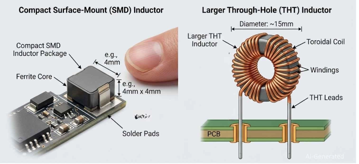
Figure: Comparison showing a compact surface-mount (SMD) inductor next to a larger through-hole (THT) inductor with long wire leads.
FAQ about SMD Inductor
Q: What Happens If Inductance Is Too High or Too Low?
If inductance is too high, the circuit responds sluggishly to transient load changes, causing voltage dips when current is suddenly demanded. If it's too low, the current ripple becomes aggressive, stressing capacitors and causing excess electrical noise.
Q: Can I Use a Higher Current-Rated Inductor?
Yes! Using an inductor with a higher Isat or Irms rating than required is completely safe and often beneficial (it runs cooler). The only downsides are increased component cost and a larger physical PCB footprint.
Q: How do I read an SMD inductor datasheet correctly?
Check inductance, Isat, Irms, DCR, and SRF. Match these with your circuit needs, not just the inductance value.
Q: What happens if I choose an inductor with too low a current rating?
It may saturate, overheat, or fail, causing instability or shutdown. Always keep a 20 - 30% current margin.
Q: How does switching frequency affect inductor selection?
Higher frequency → lower inductance needed. Lower frequency → higher inductance required.Balance ripple, size, and efficiency.
Q: Can I replace an SMD inductor with a different value?
Small changes may work in power circuits. In RF circuits, even slight changes can break performance.
Q: Are larger SMD inductors always better?
No. Larger = higher current and lower DCR, but greater size and cost. Choose the smallest safe option.
Conclusion
Choosing the right SMD inductor doesn't have to be a guessing game. By remembering that selection depends heavily on the application, you can quickly narrow down your choices. For power circuits, prioritize Current (Isat/Irms) and DCR above all else to ensure thermal stability and efficiency. For signal and RF circuits, prioritize the exact Inductance value and SRF to maintain signal integrity.
From prototype to production, consistent PCB fabrication and assembly ensure your selected inductors perform reliably. Once you have done the math and picked the perfect components, you can turn your verified designs into reality by getting a fast quotation for high-quality, affordable bare boards and reliable JLCPCB PCBA service, ensuring your power and RF circuits perform exactly as designed.
Popular Articles
• SMD Diode Code Lookup: Full List, Marking Guide & Identification [2026 Guide]
• SMD Resistor Package Sizes: Complete Size Chart, Footprints & How to Choose
• SMD Capacitor Codes: Identification, Markings, and Polarity
• SMD Capacitor Sizes: Complete Size Chart and Selection Tips for PCB Design and Assembly
• How to Solder SMD Components Like a Pro [2026 Updated]
Keep Learning
PoP Package (Package on Package) Explained: Architecture, Assembly, and SMT Challenges
In the race for miniaturization, fitting more processing power into smaller footprints is the ultimate challenge for PCB designers. Package on Package (PoP) technology answers this by integrating logic and memory vertically, becoming the standard for modern mobile processors. However, this 3D architecture demands advanced SMT assembly capabilities beyond standard fabrication. JLCPCB specializes in the high-precision manufacturing required to master these complex stacks. This guide covers how PoP packa......
What Is a PQFP Package? Plastic Quad Flat Package Design, Footprint, and Assembly Guide
The Plastic Quad Flat Package (PQFP) is a widely used IC package in industrial, automotive, and embedded designs. This article provides a practical, engineering-focused guide to PQFP package. It explains how PQFP is built, when it makes sense to use it, how it compares with newer package types, and what designers should consider in terms of footprint design, thermal performance, signal integrity, manufacturing, and reliability. What Is a PQFP Package (Plastic Quad Flat Package)? A Plastic Quad Flat Pa......
Small Outline Integrated Circuit (SOIC): Package, Specs & Uses
As designs transition from legacy through-hole components to high-density Surface Mount Technology (SMT), the Small Outline Integrated Circuit (SOIC) remains the industry standard for operational amplifiers, flash memory, sensors, and microcontrollers. It stands as a testament to balanced engineering, offering a perfect compromise between the miniaturisation demanded by modern consumer electronics and the ruggedness required for industrial applications. This article serves as a definitive engineering ......
A Complete Guide to Surface Mount Device (SMD)
Imagine holding a smartphone in your hand. Inside that sleek device lies a complex network of thousands of miniature components — resistors smaller than a grain of rice, capacitors thinner than a fingernail, and integrated circuits containing millions of transistors. Without Surface Mount Technology (SMT) and its compact Surface Mount Devices (SMDs), none of this would exist. Just a few decades ago, electronics were bulky. Radios filled desks, computers filled rooms, and assembling a circuit meant dri......
Circuit Breaker Types Explained: MCB, MCCB, RCCB, RCBO, ACB, VCB & SF6 Circuit Breakers
A circuit breaker automatically disconnects power when it detects faults such as overloads or short circuits, protecting equipment and reducing fire risk. Different circuit breaker types are designed for different voltage levels, current ratings, and applications, from household distribution boards to high-voltage substations. This guide explains the most common types - including MCBs, MCCBs, RCCBs, RCBOs, ACBs, VCBs, and SF6 breakers and helps you choose the right one for your application. Figure: Ci......
Quad Flat Package (QFP): The Engineer's Guide to Design, Assembly and Thermal Management
What is QFP Package? The Quad Flat Package (QFP) is one of the most popular surface mount technology (SMT) package formats throughout the history of electronic manufacturing. After it became standard in the 1980s, the QFP has been the industry standard for integrated circuits (ICs) with moderate to high pin counts that typically range from 32 to 304 pins, so it was a good alternative for simple SOIC packages and complex Ball Grid Arrays (BGAs) at the same time. Defined by its "gull-wing" leads extendi......