Why PCB Substrate Choice Matters More Than You Think
17 min
- What Is a PCB Substrate?
- The Core Functions of a PCB Substrate
- Exploring PCB Substrate Materials
- PCB Substrate Types for Different Applications
- How to Select the Right PCB Substrate
- How JLCPCB Turns the Right Substrate Into Reliable PCBs
- FAQ About PCB Substrates
- Conclusion
Key Takeaways
- Prevents Via Failures: Z-axis CTE expansion strains via barrels; right substrates prevent field failure.
- Specify Beyond FR-4: Name IPC-4101 sheets to guarantee proper Tg and lower thermal growth.
- Match Material to Need: Choose FR-4 for standard, Polyimide for flex, Aluminum for heat, and Rogers for >3 GHz.
- Use Real Fab Stackups: Prepreg weave alters Dk; compute impedance using real factory stackups.
The PCB substrate is the one part of your board you never actually draw. You choose a thickness, select FR-4, and move on. Yet a board that passed every electrical test can still come back from the field because a via barrel has failed.
A laminate is closer to reinforced concrete than plastic. The woven glass cloth is the rebar, while the cured epoxy is the cement. The glass provides most of the mechanical strength across the board, but there is no equivalent reinforcement running through the thickness. That leaves the resin free to expand vertically much more than it expands sideways. During every reflow cycle, that expansion puts stress on the copper barrel inside plated-through holes.
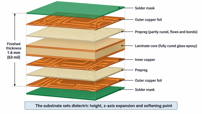
Figure 1: Stacked copper-clad laminate sheets and prepreg
This guide explains what the PCB substrate actually does, which laminate properties matter in practice, and how they can affect reliability and electrical performance. It then compares standard FR-4, high-Tg, flexible, and RF materials, and shows how to choose the right one for your design.
What Is a PCB Substrate?
Everything else on a printed board is either copper or a coating over copper. So the substrate has two jobs to do at once:
- Holding everything in place
- Keeping the layers separated
What Is PCB Substrate and Where Is It Used?
A PCB substrate is the insulating base material that supports the copper circuitry. In a rigid board, it is a cured composite of woven glass cloth and thermoset resin, supplied as copper-clad laminate. Every trace you route sits on it, so every layer you add is separated by another sheet of it.
The name covers four products you will actually meet:
- Rigid glass-epoxy laminate: Cured cores bonded together by prepreg, and the default for almost every board.
- Polyimide film: A thin, flexible base that folds without cracking, used for FPC tails and ribbons.
- Metal-core laminate: A thin dielectric pressed onto an aluminum or copper plate to pull heat out.
- Hydrocarbon-ceramic or PTFE laminate. Low-loss materials for signals above a few gigahertz.
So the differences between them come down to how much heat, bending and frequency the application throws at the board.
The Role of Substrate in PCB Construction
Copper-clad laminate arrives as a cured sheet with copper foil bonded to one or both faces. Etching removes the copper you do not want. What remains is your circuit, sitting on an insulator that was already underneath it. A multilayer board is built by stacking those etched cores with prepreg between them. Prepreg is the same glass cloth carrying resin that is only partly cured. That means it melts and flows under heat and pressure before it hardens.
So a finished four-layer board is one continuous block of material, not a sandwich held together by glue. The substrate then fixes three things you cannot adjust afterward. It sets the dielectric height between a trace and its reference plane, which means it sets impedance. It determines how much the board grows in thickness during reflow. And it sets the temperature at which the resin softens and releases the copper.
The Core Functions of a PCB Substrate
A substrate is doing three jobs at once, and they pull against each other. Insulating cleanly, staying stiff, and shedding heat rarely come from the same resin system.
Electrical Insulation and Signal Performance
Insulation is the obvious job, and the substrate does it easily at low voltage. Volume resistivity for standard FR-4 grades runs above 10^8 megohm-cm. So leakage between adjacent nets is almost never the limiting factor on a signal board. What matters far more is how the material stores energy.
- Dielectric constant, written as Dk, describes the storage, and it sets both trace impedance and propagation delay. Standard FR-4 sits near 4.5 at 1 MHz but drops into the low fours at 1 GHz.
- Dissipation factor, written as Df, determines how much of your signal is converted into heat within the resin. FR-4 grades range from 0.011 to 0.018 at 1 GHz. Rogers RO4350B, a hydrocarbon-ceramic laminate, has a dielectric constant of 0.0037 at 10 GHz. That gap is why a 5 GHz antenna feed on FR-4 loses several tenths of a decibel per inch.
Mechanical Support and Thermal Management
Stiffness comes from the glass cloth rather than from the resin. Woven E-glass gives a standard laminate a flexural strength of around 500 MPa along the warp direction. That is what stops the board flexing under a heavy connector or a tall electrolytic capacitor.
Glass-epoxy conducts at roughly 0.3 W/mK, which puts it closer to a thermal insulator than to a heat spreader. So the copper planes end up doing nearly all of the spreading. That is why lighting and power boards move to a different base entirely.
Aluminum laminate has a thermal conductivity of about 0.82 W/m·K, less than three times that of FR-4. Yet its measured thermal resistance can still be around 0.198 °C/W. The reason is simple: heat travels through a layer only about 0.1 mm thick instead of 1.6 mm (63 mil). In aluminum PCBs, the real thermal advantage comes from the much thinner heat path, not just the metal itself.
How Substrate Properties Affect PCB Reliability
Reliability failures trace back to the substrate more often than to the copper, and they almost always arrive through heat. Every reflow cycle takes the board past the point where the resin softens. Once it does, the material stops behaving the way your mechanical intuition expects.
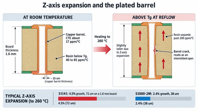
Figure 2: Z-axis expansion at reflow stretching a plated through-hole barrel
- Tg (glass transition temperature): Tg is the point where the resin changes from a hard, glass-like state to a softer, rubber-like state. Below Tg, the board expands in thickness by roughly 40–65 ppm/°C. Above Tg, that expansion can jump beyond 200 ppm/°C.
- Z-axis expansion: A useful way to compare laminates is their total z-axis expansion from 50 to 260 °C. Shengyi S1141, for example, is listed at 4.5%, while the high-Tg S1000-2M is around 2.4%. On a 1.6 mm (63 mil) board, that works out to roughly 72 µm versus 38 µm of expansion. The plated barrel has to survive that movement.
- Moisture adds another problem: Moisture absorbed by the laminate can make these failures worse. During heating, trapped water can turn into steam and push the layers apart. Standard laminates may absorb around 0.09–0.15% moisture by weight.
| Property | What It Controls | Typical Standard FR-4 Value | What Goes Wrong If You Ignore It |
|---|---|---|---|
| Tg (DSC, IPC-TM-650 2.4.25) | Where the resin softens, and expansion accelerates | 135 to 140 °C | The board spends its working life near the softening point |
| Td (TGA 5% loss, 2.4.24.6) | Where the resin starts chemically breaking down | 310 to 330 °C | Repeated reflow degrades the resin permanently |
| T288 (TMA, 2.4.24.1) | Minutes before the layers delaminate at 288 °C | 2 to 30 min by grade | No headroom for rework or a second reflow pass |
| z-axis expansion, 50 to 260 °C | Vertical growth pulling on plated barrels | 2.4% to 4.5% | Barrel cracking and intermittent openings in the field |
| Moisture absorption (2.6.2.1) | Steam pressure at reflow, and Dk drift | 0.09% to 0.15% | Delamination and blistering on humid stock |
| CAF resistance (2.6.25) | Copper migration along glass bundles under bias | Grade dependent | Slow shorts between adjacent plated holes |
Exploring PCB Substrate Materials
FR-4 is not a material. It is a flammability and construction class, so two laminates can both be genuine FR-4 and behave nothing alike in an oven.
FR-4 and Other Common PCB Substrate Materials
FR-4 means flame retardant, class 4: woven glass reinforcement with a thermoset resin that passes the UL94 V-0 burn test. Nothing in that definition fixes Tg, decomposition temperature, or expansion. That is why two grades on the same shelf can differ by 40 °C in Tg. Here are a few common laminate grades, along with their key properties and relevant IPC classifications:
| Laminate Grade | IPC-4101 Sheet | Tg / Td (°C) | z-Axis Expansion, 50 to 260 °C | What It Changes for Your Board |
|---|---|---|---|---|
| Shengyi S1141 | /21 | 140 / 310 | 4.5% | Conventional FR-4, not advised above 2 oz copper, HDI, or 12 layers |
| Nan Ya NP-140F | none declared | 135 / 310 | 3.5% | Standard consumer-grade stock, fine for simple two-layer work |
| Kingboard KB-6164 | /101 | 140 / 330 | 3.5% | Normal Tg with low CTE, T288 above 15 min gives rework margin |
| Shengyi S1000H, KB-6165F | /99 | 155 to 157 / 346 to 348 | 2.8% | Mid-Tg and anti-CAF, comfortable for lead-free reflow |
| Shengyi S1000-2M | /126 | 180 / 355 | 2.4% | High-Tg and low CTE, the grade for thick, high-layer-count boards |
High-Frequency, High-TG, and Specialized Materials
High-Tg typically refers to a DSC Tg of 170 °C or higher, but the temperature itself is rarely what you are buying. What you get is lower expansion and a longer delamination time. Those come with the filled, phenolic-cured resin systems used to reach that Tg, and selecting the Tg of your PCB covers the trade-off.
High-frequency laminates solve loss rather than heat. Rogers RO4350B is a glass-reinforced hydrocarbon and ceramic material with a Dk of 3.48 ±0.05 at 10 GHz. Its Df is 0.0037, and it still runs on standard epoxy-glass production lines. It also conducts heat at 0.69 W/mK, roughly double that of a normal laminate.
PTFE laminates go further down the loss scale, reaching a Dk near 2.20 with a Df of 0.0009. PTFE laminates can exhibit z-axis expansion above 200 ppm/°C, even below Tg, making them less dimensionally stable. That is why PTFE is usually used for dedicated RF or antenna boards rather than as the substrate for an entire design.
PCB Substrate Types for Different Applications
Substrate families are usually sorted by resin chemistry, but the choice you actually make is about physical form. The board either has to stay flat, fold, or move heat.
Rigid PCB Substrates
A rigid substrate is a glass-epoxy laminate in cured sheet form, and it covers the overwhelming majority of boards ever built. Standard finished thickness is 1.6 mm (63 mil). JLCPCB builds from 0.4 to 4.5 mm (16 to 177 mil), depending on layer count. A thinner board puts less dielectric between a signal layer and its plane, so impedance falls for the same trace width. That is why a 0.8 mm (31 mil) four-layer board routes very differently from a 1.6 mm one. Glass-epoxy expands sideways at roughly 12 to 15 ppm/°C, while a ceramic package expands at roughly 6 ppm/°C. The mismatch loads the solder joints at the package corners on every thermal cycle. That is why a large package usually fails at its outermost joints first.
Flexible and Rigid-Flex Substrates
Flexible circuits swap glass cloth for polyimide film, and losing the glass is the entire point. Polyimide bends repeatedly without cracking, and it survives temperatures that would char an epoxy laminate. So one material serves as both the base film and the protective coverlay.
IPC-4204 is the specification for the flexible metal-clad dielectrics that these are built from. A typical two-layer flex uses a 25 µm (1 mil) polyimide core with copper on both faces. That is thin enough to fold into a hinge, and how polyimide flex circuits are built covers the rest of the stack.
Substrates for High-Speed and High-Temperature Applications
Above a few gigahertz, the substrate becomes the dominant loss mechanism, and two separate properties do the damage. Df turns signal energy into heat inside the resin. The woven glass pattern then makes Dk vary along the length of a trace.
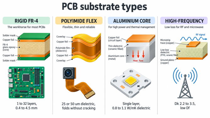
Figure 3: Side-by-side comparison of rigid, flexible, metal-core, and RF substrate
High-temperature applications pull the opposite way. An engine bay or a dense power converter can hold a board at 105 °C continuously. A grade with a Tg of 135 °C then spends its whole life near the softening point. Keeping the maximum operating temperature 20 to 30 °C below Tg helps keep expansion within the predictable linear region.
How to Select the Right PCB Substrate
Substrate selection has two halves, and people usually run them in the wrong order. Decide what the circuit needs first, then check what the fab can actually press this week.
Electrical, Thermal, and Mechanical Requirements
Start from the fastest edge and the hottest component on the board, because those two set the floor. Everything else, thickness and mask color included, is a preference you can adjust once the floor is fixed.
| Application | Substrate to Specify | Property That Decides It | What to Put on the Fab Note |
|---|---|---|---|
| Hobby and consumer, 2 layers, low power | Standard FR-4, Tg 130 to 140 °C | Cost | FR-4 standard Tg is enough |
| 4 to 8 layers, lead-free reflow, commercial | Mid-Tg FR-4, IPC-4101/99 | z-axis expansion near 2.8% | Name the slash sheet, not a brand |
| 12+ layers, thick boards, automotive | High-Tg FR-4, IPC-4101/126 | T288 above 30 min | Specify Tg 170 °C minimum, low CTE |
| RF and antenna work above 3 GHz | Rogers RO4350B or PTFE | Df at the operating frequency | Give the Dk target and its tolerance |
| High-power LED and motor drivers | Aluminum core, 0.8 to 1.1 W/mK | Thermal resistance, not conductivity | State the dielectric layer thickness |
| Hinges, camera modules, wearables | Polyimide flex per IPC-4204 | Bend radius and cycle count | Specify coverlay and stiffener zones |
Layer Count, Stack-Up, and Manufacturing Compatibility
Layer count turns the substrate question from a single material into a set of materials. A four-layer board is built from a core plus prepreg plies. The prepreg glass style then sets the dielectric height between your signal layer and its reference plane.
Prepreg styles are not interchangeable.
- 7628: presses into a thicker dielectric layer, with a Dk of about 4.4.
- 3313: presses into a thinner layer, with a Dk of about 4.1.
So, changing the prepreg style can change both the final layer thickness and the effective dielectric constant. So choosing the right prepreg shifts your impedance before a single trace is drawn. Work through the stackup in this order, since each step constrains the one after it:
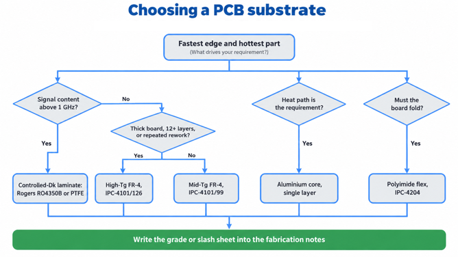
Figure 4: Decision flow from circuit requirements to a named substrate grade
- Fix the finished thickness and layer count from your mechanical and routing needs.
- Ask the fab for its published stackup for that exact combination, including pressed dielectric heights.
- Check the laminate grade in that stackup against the thermal requirement you set earlier.
- Feed the real prepreg Dk into your impedance calculation rather than a generic 4.5.
- Write the grade or the slash sheet into the fabrication notes so it survives into production.
A non-standard laminate brings a minimum order quantity and a longer lead time. So, a good grade that is already on the shelf usually beats a marginally better one that has to be ordered in.
How JLCPCB Turns the Right Substrate Into Reliable PCBs
A fab contributes two things to substrate quality. One is which laminates it keeps in stock, and the other is whether it can prove afterward what went into your board.
Matching Substrate Selection With JLCPCB Manufacturing Capabilities
JLCPCB builds standard rigid orders on Grade A FR-4 laminates from Nan Ya, Kingboard, and Shengyi, across 1 to 32 layers. The JLCPCB certifications page publishes the actual supplier datasheets. So the grades listed earlier are grades whose numbers you can read before you order. Outside FR-4, the range narrows, and knowing the edges saves a redesign. Aluminum-core and copper-core boards are single-layer only. RF boards are two-layer, with Rogers or PTFE cores and 1 oz copper. Flexible circuits are available in 1, 2, and 4-layer configurations on polyimide, with 25 or 50 µm (1 or 2 mil) inner dielectric.
From Material Control to Consistent PCB Quality
Material control starts well before lamination. Laminate and prepreg need to be stored under controlled temperature and humidity because prepreg can absorb moisture, which can reduce its bonding strength. Shengyi, for example, specifies a storage life of only three months below 23 °C for some of its prepregs. That makes proper storage and stock rotation important.
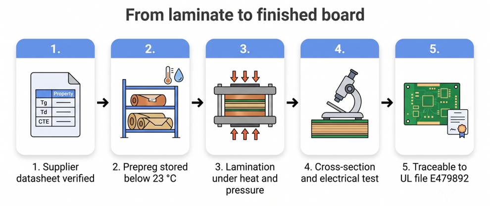
Figure 5: Substrate control workflow from Laminate inspection to the finished board
At the design stage, the process is straightforward:
- Decide the thermal and frequency requirements of the board.
- Choose a laminate grade that meets those requirements.
- Clearly specify the material in the fabrication notes.
- Upload the design for a fabrication quote.
- Review the DFM report before approving the build.
FAQ About PCB Substrates
Q: Is FR-4 a single material or a category?
It is a category. FR-4 describes a woven glass and thermoset resin construction that passes the UL94 V-0 flammability test, and nothing more. Grades within it range from Tg 135 °C to over 180 °C, so the useful specification is an IPC-4101 slash sheet or a named laminate.
Q: Do I need high-Tg material for a normal four-layer board?
Usually not. A standard or mid-Tg grade handles lead-free reflow comfortably on a thin board with short plated barrels. High-Tg earns its cost on thick boards, high layer counts, repeated rework, or continuous operation above about 100 °C.
Q: What does z-axis CTE have to do with via failures?
Above Tg, the resin expands through the board thickness at more than 200 ppm/°C, while the copper barrel expands at about 17 ppm/°C. The resin stretches that barrel on every heating cycle. After enough cycles, the barrel cracks and reads as an intermittent open.
Q: How do I make sure my board is built on the grade I want?
Write the laminate grade or the IPC-4101 slash sheet into the fabrication notes, not just in an email. Fabs select from an approved list at their own discretion unless you specify. An unstated requirement gets met by whatever qualifies as FR-4 that day.
Conclusion
The PCB substrate stops being a checkbox once you treat FR-4 as a category rather than a product. Two laminates carrying the same UL designation can differ by 40 °C in Tg and by nearly half in z-axis expansion. That second number decides whether your plated barrels survive a few years of thermal cycling. None of these properties is exotic; they simply sit on a page most designers never open.
Three habits carry most of the benefit. Name a grade or an IPC-4101 slash sheet instead of writing FR-4. Take Dk from the fab's published stackup rather than from memory, and keep the operating temperature well below Tg. Boards keep getting thinner, denser, and more thermally loaded, so the margin that used to hide a careless material choice is shrinking. JLCPCB publishes its supplier datasheets, which makes the checking quick enough to do on every design.

Keep Learning
Safeguarding Circuit Boards Against Breakdown Voltage Failure
Key Takeaways Construction Matters: Breakdown voltage depends on stackup and defects, not raw material ratings. Stress Causes Failures: Heat and moisture degrade insulation over time, leading to field defects. Four Main Failure Modes: Insulation fails via internal voids, treeing, CAF growth, or surface tracking. Layout Design Fixes: Use dual prepregs, wider hole spacing, rounded trace corners, and isolation slots. Testing Split: Bare-board testing checks low-voltage net continuity, while hi-pot tests ......
Is FR4 the Best Board Material for Your Design
Key Takeaways Best All-Rounder: Ideal balance of strength, insulation, and low cost for standard PCBs. Clear Limits: Poor heat dissipation (~0.3 W/m·K) and high loss for RF (>3 GHz). Alternatives: Use Rogers for RF, Aluminum for high heat, and FPC for flexibility. Selection Essentials: Pick High-Tg (170°C+) for lead-free reflow and custom stackups for impedance. JLCPCB Advantage: 1–32 layer FR4 boards with ±10% impedance control and 24h fast dispatch. In the world of electronics and printed circuit bo......
Optimizing High-Voltage Circuit Safety with PCB Dielectric Strength
Key Takeaways Non-linear Scaling: Dielectric strength drops as thickness increases. Safety vs Signals: Dielectric strength ensures safety, while Dk controls signal speed. Material Selection: High-voltage safety depends on Tg, CTI, and moisture resistance. Spacing Rules: Clearance prevents air arcs, while creepage prevents surface tracking. Assembly Testing: Hi-pot testing requires finished assemblies, not bare boards. Dielectric strength is the number engineers quote to prove a board is safe at mains ......
How Copper Foil Shapes PCB Performance and Manufacturing Quality
Key Takeaways Weight: 1 oz copper ≈ 35 µm thickness; higher weight increases current capacity. Types: ED for standard rigid boards, RA for dynamic flex circuits. DFM & Loss: Smoother foil lowers RF loss; thicker foil requires wider trace spacing. The part of a PCB that actually carries the electrical signal is the copper foil. The strength comes from the glass weave, the resin is used to keep the layers together, and the solder mask is used to provide protection and separation of exposed copper. But w......
Why PCB Substrate Choice Matters More Than You Think
Key Takeaways Prevents Via Failures: Z-axis CTE expansion strains via barrels; right substrates prevent field failure. Specify Beyond FR-4: Name IPC-4101 sheets to guarantee proper Tg and lower thermal growth. Match Material to Need: Choose FR-4 for standard, Polyimide for flex, Aluminum for heat, and Rogers for >3 GHz. Use Real Fab Stackups: Prepreg weave alters Dk; compute impedance using real factory stackups. The PCB substrate is the one part of your board you never actually draw. You choose a thi......
A Complete Guide to Copper Clad Laminate (CCL) in PCB Manufacturing
Key Takeaways CCL is the base material: a cured resin-reinforcement sheet with copper foil bonded to one or both sides. Three parts control performance: Resin affects heat and loss, reinforcement controls stability, and copper foil affects conductor behavior. Choose by the main design stress: Heat, frequency, and cost usually determine the best laminate family. Slash sheets define the material: IPC-4101 uses numbered slash sheets to specify rigid PCB base materials. Tg alone is not enough: Td and time......