Polyimide Flexible Circuit Boards: The Ultimate Material and Design Guide
17 min
- What Is a Polyimide Flexible Circuit?
- Polyimide vs. FR4: Why PI Is the Gold Standard for Flex PCBs
- Key Design Guidelines for Polyimide Flexible Circuits
- Impact of Polyimide Substrates on Impedance Controlled Circuits
- What Affects the Cost of Polyimide Flexible Circuits?
- Why JLCPCB Is Your Premier Partner for Polyimide Flex PCB Manufacturing
- Conclusion
- FAQ
Ever open up a folding device like a phone, a camera module, or a wearable fitness band, and ask yourself how the electronics can survive being bent thousands of times without breaking? Most often, the secret is a polyimide flexible circuit. This thin, amber-colored film is what's doing the work on most products that need to fold, twist, or wrap around a curve. Rigid FR4 boards make for great power supplies and motherboards, but they break if you bend them.
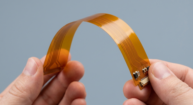
Polyimide, however, was almost invented to withstand motion, heat, and tight confines. That's why it has become the standard substrate for flex and rigid-flex consumer, automotive, aerospace, and medical electronics. This guide will take you through what polyimide is, why it's not always the same as FR4, how to design a reliable flex circuit around it, copper options, bending radius, impedance control, and the true cost drivers you'll face while procuring polyimide. Let's get into it.
What Is a Polyimide Flexible Circuit?
A polyimide flexible circuit is a PC (printed circuit) circuit printed on a base of polyimide (PI) film rather than the more common glass-reinforced epoxy circuit board. The polyimide film becomes the dielectric substrate, the copper foil becomes the conductor,r and a coverlay (a second layer of polyimide) replaces the solder mask to protect the traces.
Polyimide is a high-performance polymer with excellent thermal stability and ductility. As it does not have woven glass reinforcement, unlike FR4, it will not crack when bent. Many suppliers produce grades of PI film that are equivalent to DuPont's Kapton, which is best known. The most frequently used thicknesses of film that you'll mention are 12.5 µm (½ mil), 25 µm (1 mil), and 50 µm (2 mil). Thinner films are more flexible and used for dynamic bend applications, and thicker films are more rigid and provide mechanical support. This versatility, along with their extremely high temperature resistance, is why polyimide is the main component of the flexible PCB material options today.
Polyimide vs. Polyamide: Understanding the Chemical Differences
The problem is, polyimide and polyamide confuse many engineers, and the only difference between the two is a single letter. They're chemically different materials, and it can cause actual problems if they are confused on a datasheet or purchase order.
Polyimide is a polymer with the imide functional group (N attached to two carbonyl) in its structure. The added weight of this ring structure provides it with excellent heat resistance and dimensional stability, and that is why it is used in flex circuits. Polyamide (or nylon, as it is commonly called, or Kevlar) is made from the amide linkage. Not the same thermal or electrical properties required to use as a circuit substrate, but a common engineering plastic/fiber. If "PI" is on a flex component stackup, it is always polyimide, never polyamide.
Flexible Circuit Material Construction: Adhesive vs. Adhesiveless PI Film
The polyimide laminate is basically a copper foil attached to a polyimide film; the way this bond is formed is very important. The construction is of two types: adhesiveless and adhesive bonding.
In adhesive-based laminates, the copper is bonded to the polyimide with an adhesive, such as acrylic or epoxy. They have a high coefficient of thermal expansion (CTE) and are softer mechanically, but are also less expensive and more accessible.
In adhesiveless laminates, copper is cast directly on the PI film, or a seed layer is sputtered. Thinner, more thermally stable, and suited for fine-line and high-frequency applications.
The choice is usually between adhesiveless material and other designs that are dynamic-flex, high-density, or impedance-controlled. For repeated bending and thermal cycling, as we will see, the weak link is the acrylic used in adhesive-based stacks.
Polyimide vs. FR4: Why PI Is the Gold Standard for Flex PCBs
If polyimide is more costly than FR4, why use it? If flex circuits simply don't want to be dealt with FR4. FR4 is a hard, tough, and cost-effective woven fiberglass-epoxy composite material that is brittle. If bent too far, the glass fibers will break, carrying your copper traces with them.
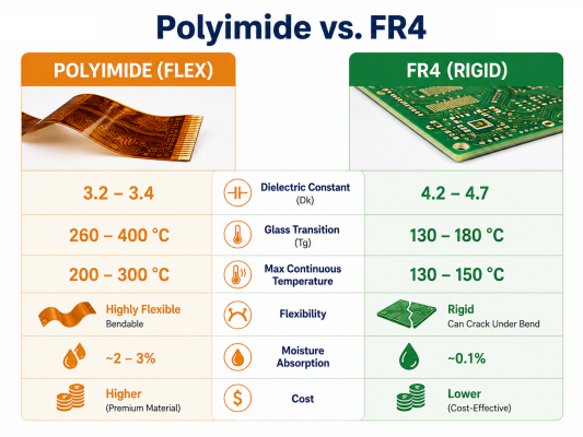
Polyimide is a non-reinforced, very ductile material. It can be bent, folded, and wrapped without harm around 3-D assemblies, allowing designers to reduce product size and eliminate bulky wire harnesses and connectors. That one feature is what makes the polyimide flex PCB the go-to choice for any product that requires flexibility and/or movement, or that needs to fit into a small enclosure. The two materials are compared side by side below:
| Property | Polyimide (Flex) | FR4 (Rigid) |
| Reinforcement | None (ductile film) | Woven glass + epoxy |
| Dielectric Constant (Dk) | 3.2 – 3.4 | 4.2 – 4.7 |
| Glass Transition (Tg) | 260 – 400 °C | 130 – 180 °C |
| Max Continuous Temp | 200 – 300 °C | 130 – 150 °C |
| Flexibility | Excellent (dynamic bend) | Poor (cracks when bent) |
| Moisture Absorption | Up to 2 – 3 % | 0.1 % |
| Relative Cost | Higher | Lower |
Thermal Stability, Tg (Glass Transition Temperature), and Heat Resistance
Polyimide is the clear star when it comes to thermal performance. Glass transition temperature (Tg) is the temperature at which a polymer becomes soft from the glassy state to the rubbery state. The temperature of standard FR4 is approximately 130-180 °C, while the polyimide films are much higher, typically 260 °C to 400 °C, depending on the grade. In the case of Kapton HN, the Tg value is very low or, in fact, not measurable at all because the film does not soften up to its decomposition temperature.
Typical operating temperatures are between -200 °C and 300 °C, and further depending on the type of specialty. This headroom matters. Polyimide is used in flex circuits, and they are routinely through-reflowed at 245-260 °C, and function without issues.
Mechanical Endurance: Continuous Flexing and Tensile Strength
In addition to its thermal resistance, polyimide has good mechanical strength. For instance, DuPont's Kapton HN has a tensile strength of approximately 231 MPa at 23 °C and retains approximately 139 MPa at 200 °C, and a tensile modulus of ~2.5 GPa. The strength and elasticity are the reasons for a trace being able to survive being folded over and over. The most important difference is between static and dynamic flexing:
- Static (flex-to-install) circuits are bent at the time of assembly and remain that way. They are able to handle a sharper radius of bend and higher thicknesses of stack.
- Dynamic flexing circuits are in continuous service, such as a printer head, laptop hinge, or hard-drive actuator, and are required to endure millions of cycles.
With dynamic designs, material choice, copper type, and layer count all become critical. A single-layer dynamic flex with the correct design can last for many millions of bend cycles, and the same design on a copper or on a too-tight radius could fail in the thousands.
Key Design Guidelines for Polyimide Flexible Circuits
Controlling Flexible PCB Material Thickness and Layer Stackup
The biggest lever to flex circuit bending is the thickness of the stack. Thinner is more flexible, bend stress rises quickly with thickness; therefore, dynamic designs are played with thin films and low layer counts. Here are a couple of rules you have to follow when building your stackup:
- Limit dynamic-flex to one or two layers of copper. Each additional layer increases the stiffness of the bend area and increases the stress of the outermost traces.
- The thinnest PI film possible to meet the specified requirements is used, typically 12.5µm or 25µm for the flexing area.
- Don't use plated through holes and vias in the bend area, as these items are stress concentrators and crack out early.
- Keep the neutral bending axis in the middle of the layers, or the board will curve.
- Add stiffeners outside the flex zone, under the connector/components, only to localize where bending will occur.
Symmetry as your ally. Using a balanced and symmetric stackup helps to maintain the correct neutral axis and avoids warping found in buildings with flex that stack up asymmetrically.
Choosing the Right Copper Types: RA Copper vs. ED Copper
The choice of copper is the key to the successful implementation of flex design, and it hinges on the choice between RA copper and ED copper. They are produced in two completely different ways and have entirely different grain structures, which react differently when bent.
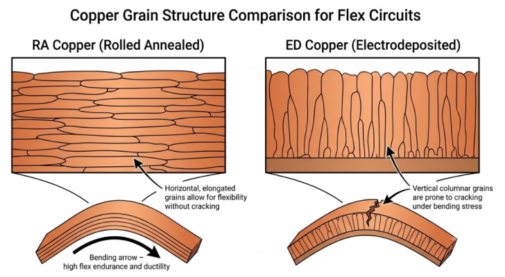
The electrodeposited (ED) copper is deposited on a drum, where the grain structure is vertical and columnar. Low cost and is standard on rigid FR4, but the vertical grains cause sites for crack initiation, resulting in poor flex life.
Rolled annealed (RA) copper is mechanically rolled and heat-treated, making the grains in the copper elongated into a horizontal, ductile structure along the length of the copper sheet. That grain direction allows it to bend and flex many more times without cracking; for a thickness of 0.004" RA copper can flex as many as 10 times as many times as ED can at the same thickness.
| Attribute | RA Copper | ED Copper |
| Process | Rolled + annealed | Electroplated on the drum |
| Grain structure | Horizontal, elongated | Vertical, columnar |
| Flex endurance | Excellent (dynamic) | Poor (static only) |
| Cost | Higher | Lower |
| Best use | Dynamic flex, hinges | Static bend, low cost |
The general principle: use RA copper for dynamic-flex (where cycle life is more important than cost); use ED copper for static flex-to-install (where cost is more important than cycle life).
Managing the Bending Radius and Neutral Axis to Prevent Trace Cracking
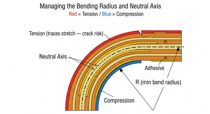
Each flex circuit has a neutral axis, which is an imaginary plane that runs through the thickness of the flex circuit where bending causes no tension or compression on the material. Copper on the neutral axis will have the smallest strain and will be the most durable. The outer curve, on bending, the board gets stretched, and the inner curve gets compressed. Cracks begin at the outer surface where there is the most tensile stress. The more contained the bend, the greater the strain, so there is no room for compromise as far as minimum bend radius. General industry guidelines for minimum bend radius (in multiples of overall flex thickness) are:
- Single-layer flex: 6 × thickness (static) / greater (dynamic)
- Double-layer flex: 10× thickness
- Formability: Excellent to very good
- Dynamic-flex applications: typically 20-40X thickness with a long cycle life.
Make sure that traces are perpendicular to a bend, have ample width where flexing will occur, and avoid sudden width changes, as well as stack traces in opposite layers instead of staggering them. The actions maintain low copper strain and greatly reduce cracking risks.
Impact of Polyimide Substrates on Impedance Controlled Circuits
Flex circuits are now used for carrying a wide variety of high-speed signals, such as USB, MIPI, LVDS, and others, as data rates continue to rise, making impedance control a key aspect. The electrical properties of polyimide directly determine the performance of the target, such as 50Ω single-ended or 90/100Ω differential. Since everything on a flex is thin, any change in film thickness, coverlay, and adhesive will cause a change in impedance, so modeling the entire stack (not just the trace and one dielectric) is necessary.
High-Frequency Signal Integrity and Dielectric Constant (Dk/Df)
One of the quiet benefits of the polyimide is its dielectric constant. The Dk of polyimide is ~3.2-3.4, which is significantly less than that of FR4 (~4.2-4.7). A lower Dk results in faster propagation of signals and, for a given impedance, can be used with slightly wider traces, which is useful if the dielectric is microns thin.
The dissipation factor (Df), which regulates signal loss, is just as important. The Df for pure polyimide films can be very low, for some grades of Kapton, as low as 0.002 at kHz frequencies, although more realistic flex stacks with adhesive will have a higher Df. The lower the Df, the less attenuation, so the faster the edge rates, the more important it is. Remember that moisture (a few percent by weight) is absorbed by polyimide, and absorbed water increases Dk and Df. When working with demanding RF applications, be sure to use low moisture grades, bake prior to the lamination process, and factor humidity into your impedance budget.
How Acrylic Adhesives Affect Impedance Stability
Recall the difference between adhesive and adhesion-free? It comes roaring back for impedance-controlled designs. Many laminates and coverlays use an acrylic adhesive with its own value of the dielectric constant and, importantly, a high CTE.
Two problems arise: the first is that the adhesive introduces an additional variable-thickness (Dk) layer into the system, making it more difficult to predict and control. Second, acrylic has a high thermal expansion coefficient, causing the stack thickness to change with temperature and nudging the impedance around during reflow and in the field. If close tolerances of impedance are required (e.g., ±10%), adhesiveless laminates are strongly preferred. Post-acrylicization provides a predictable and cleaner dielectric and tighter impedance control. Always use an actual stackup in your manufacturer's calculations, and then perform an impedance calculation with the real stackup, not just a guess.
What Affects the Cost of Polyimide Flexible Circuits?
Manufacturing Cost Drivers: Material Thickness, Layer Counts, and Stiffeners
Structural costs are the largest cost drivers. The more layers, the more material, and the more mechanical add-ons, the more expensive it is:
- Adding layers to the copper increases the number of lamination cycles, the amount of drilling, and the yield loss.
- Copper thickness and material: Thicker copper and PI films are more expensive and may be more difficult to etch fine lines.
- Add material and manual assembly with stiffeners: PI, FR4, or steel stiffeners under connectors.
- Adhesiveless vs. adhesive laminate: Adhesiveless material has a higher price but works better.
- Coverlay vs. flexible solder mask: Laminated coverlay is more durable, but requires a registration and lamination process.
- Tight tolerances: Controlled impedance, fine lines/spaces, and small vias all drive up cost due to increased inspection and decreased yield.
Designing for Cost Optimization (DFM Advice for Procurement)
The cheapest and quickest way to make a flex quote cheaper without compromising reliability is good design-for-manufacturing (DFM). Some measures to facilitate the procurement:
- Minimize the number of layers: Merge layers to the minimum number needed for your signals and mechanics.
- Only every 3 mil does not need to be a trace.
- Use the standard material thicknesses for common film and copper for your fab.
- Minimize the use of stiffeners, and use PI instead of steel, if possible.
- Panelize efficiently (economize and minimize wasted space) for multiple circuits to be combined on a panel.
- Only identify controlled impedance for the nets that require it, and not for the entire board.
The reward paid is tangible: a design that incorporates standard abilities and reasonable tolerances can be at a much lower cost than a design that is overspecified and then overqualified, and it will perform the same in the field.
Why JLCPCB Is Your Premier Partner for Polyimide Flex PCB Manufacturing
Industrial-Grade Material Sourcing
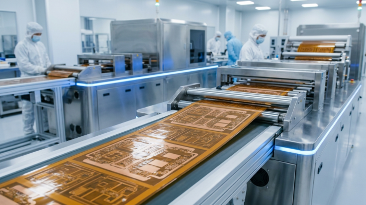
The quality of the laminate begins at the source. JLCPCB suppliers provide polyimide films and copper foils for use in industry, so you have the right RA copper and adhesiveless films, which are required by dynamic-flex and impedance-controlled designs. The lamination process is also crucial. The flex reliability of these void-free, dimensionally stable stacks relies on advanced vacuum lamination equipment that creates the void-free, dimensionally stable stacks. The key difference for a flex that lasts a million cycles versus one that fails in the field is consistent lamination.
Free Automated DFM Support to Flawlessly Secure Your Flex Yields
Miss one little detail, like a via in a bend area, or a trace parallel to a fold line, and flex circuits will take their toll and ruin your yield. These problems are best identified before your design reaches the production line with JLCPCB's free automated DFM checks. The system identifies areas of potential hazards, spacing issues, and stackup issues early on, allowing you to address them in CAD before they are discovered during tooling. In flex work, it is important that the front-loaded feedback allows for a first pass right build; in case of a single mechanical error, the batch can be scrapped.
High-Quality Prototyping to Mass Production with Instant Online Quoting
If you're trying to validate a prototype or if you're getting ready to ramp to volume, JLCPCB's quick online quoting process will enable you to cost-up a flex build in mere seconds, and modify the design based on the cost feedback that's the same loop that the above DFM-for-cost advice is designed to break.
We have a rapid turnaround, flexible pricing, and a clear path from prototype to volume production, so you can test and iterate at a rapid pace and scale without having to switch to another vendor. If you are ready to put these principles into practice, JLCPCB's flex PCB service is the easy way to go from a validated stackup to finished boards in hand.
Conclusion
Polyimide is an excellent choice for flexible electronics, and there's a reason why. It can be used in products that are easily formed to bend and fold, can withstand harsh environments and high temperatures, and have excellent electrical characteristics. The selection of film thickness, copper grain structure, and bend radius is just a few of the factors that all combine to either create a dependable flex circuit or force a failure in the field.
What is important is that flex design is a systems problem: material, mechanics, signal integrity, and cost are all interrelated. As electronics continue to shrink and bend to create wearables, foldables, and high-density 3D assemblies, the ability to master polyimide flexible circuits will only grow in importance. Combine sound design principles with a fabricator with flex capability, and you can convert even an aggressive folding design into a hardware solution that works.

FAQ
Q: What is the difference between polyimide and polyamide?
Ans: Polyimide is a heat-resistant polymer built on the imide group and is used as the dielectric film in flex circuits. Polyamide (like nylon) uses the amide linkage and is an engineering plastic, not a circuit substrate. On any flex stackup, "PI" always means polyimide.
Q: What is the dielectric constant of polyimide flex material?
Ans: Polyimide's dielectric constant (Dk) is roughly 3.2 to 3.4, notably lower than FR4's 4.2 to 4.7. The dissipation factor can be very low for pure films, but it rises when acrylic adhesive is present. This lower Dk helps high-speed signal integrity on thin flex stacks.
Q: Why is RA copper preferred over ED copper for flex circuits?
Ans: Rolled annealed (RA) copper has an elongated, horizontal grain structure that flexes repeatedly without cracking. Electrodeposited (ED) copper has vertical columnar grains that initiate cracks under bending. For dynamic-flex applications, RA copper delivers far greater bend-cycle life.
Q: What is the minimum bending radius for a polyimide flex PCB?
Ans: A common rule of thumb is about 6× the total thickness for single-layer static flex, 10× for double-layer, and 15–20× or more for multilayer. Dynamic-flex designs often require 20–40× thickness for long cycle life. Keeping vias and abrupt features out of the bend zone is equally important.
Q: Can polyimide handle lead-free reflow soldering?
Ans: Yes. Polyimide films remain dimensionally stable well above lead-free reflow peaks of 245–260 °C, with Tg values commonly quoted from 260 °C up to around 400 °C. This heat resistance is a major reason it outperforms FR4 in flex and high-temperature applications.

Popular Articles
• Choosing the Right Bend Radius for Durable Flexible PCBs
• Flexible Meets Durable: Understanding Rigid-Flex PCB Technology
• PCB Stiffeners: An Essential Requirement for Flexible Circuits
• The Ultimate Guide to Flexible PCB: Types, Design, and Applications
• 45 Must-Know Flex PCB Design Tips You Can't Afford to Miss!
Keep Learning
Choosing the Right Bend Radius for Durable Flexible PCBs
Key Takeaways Mastering the bend radius is essential for reliable flexible PCB design. Following IPC-2223 guidelines, maintain a minimum of 6× total thickness for static bends and 100× for dynamic applications, while using thinner RA copper, adhesiveless polyimide, staggered traces, and cross-hatched patterns in flex zones. Proper material selection, layer stackup optimization, and adequate clearance from stiffeners can dramatically extend flex life and prevent premature trace cracking or delamination......
Flex PCB Stackup Design Guide: Layers, Materials & Reliability
Key Takeaways A reliable flex PCB starts with the right stackup design. The layer structure, material selection, and copper arrangement directly affect flexibility, bend life, electrical performance, and manufacturing reliability. This guide explains single-sided, double-sided, and multilayer flex PCB stackups, including polyimide materials, coverlay, copper types, and key design considerations for creating durable flexible circuits with JLCPCB. Did you ever wonder how a foldable phone can last for 20......
Flexible Meets Durable: Understanding Rigid-Flex PCB Technology
In the rapidly evolving world of electronics, the demand for smaller, more reliable, and more versatile devices continues to grow. To meet these demands, engineers and designers are increasingly turning to Rigid-Flex PCBs. The circuit boards combine rigid and flexible substrates into a single interconnected structure. This combination allows for complex designs that can bend and flex in specific areas while maintaining rigidity in others. To manufacture rigid flex PCBs, IPC offers advice and best prac......
PCB Stiffeners: An Essential Requirement for Flexible Circuits
A printed circuit board stiffener plays an important role when it comes to offering mechanical support to a PCB. They are particularly helpful for flexible circuit boards, that given their name, are flexible and in need of stiffness in certain places. Stiffeners are particularly required when components are placed in a flex zone & the weight of these components stresses the flex material. These components provide a rigid connection from the flexible portion to the solid board. This solidity makes appl......
The Ultimate Guide to Flexible PCB: Types, Design, and Applications
Key Takeaways JLCPCB 1–4 Layer Flex PCB: Supports 1 to 4-layer FPCs with polyimide (PI) substrates and trace/space down to 3/3 mil. Stiffener Selection: Use PI (0.1–0.25mm) for ZIF connectors, FR4 (0.1–1.6mm) for SMT support, and Stainless Steel (0.1–0.3mm) for high rigidity. Layout Optimization: Use cross-hatched copper ground planes and stagger 2-layer traces to eliminate the "I-Beam effect." Surface & Protection: Combine Immersion Gold (ENIG 1u"/2u") for SMT planarity with flex coverlay to protect ......
Medical Flex Circuits: Manufacturing, Applications, Materials, and Design Guide
Medical flex circuits made to fit inside a 1.0 mm disposable endoscope, wrap around a hearing aid shell, and sit on a patient's arm for ten straight days. When one fails, it is not a warranty return but a device history file and a regulatory conversation. In this guide, you will learn: What separates a medical flex circuit from a consumer one How they are built, tested, and released Polyimide, copper, coverlay, and stiffener choices Fine line, bend radius, and layer count limits What to check before c......