
Choosing the Right CTI Value for Safer High-Voltage PCBs
14 min
- What CTI Value Is and Why It Matters
- How CTI Value Affects PCB Safety and Reliability
- Common CTI Values Across Different PCB Materials
- Design and Manufacturing Strategies for High CTI Performance
- JLCPCB's Expertise in High-CTI PCB Production
- Conclusion
- FAQ about CTI Value
- Conclusion
Key Takeaways
- Higher CTI (≥600V, Group I) allows shorter creepage distances while preventing surface tracking in high-voltage designs.
- Standard FR4 (CTI ~175V) is often inadequate for mains voltage — upgrade to high-CTI materials for safety and compactness.
- Always match CTI material group to your working voltage and pollution degree for IEC/UL compliance.
- Clean assembly and good layout practices are essential to realize the full benefits of high-CTI laminates.
- Choose certified high-CTI materials and experienced manufacturers to ensure reliable, certifiable PCBs.
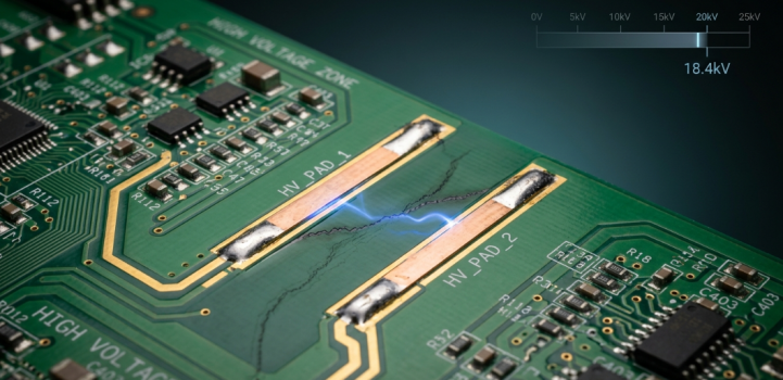
Violently, have you ever witnessed a burnt, carbonized track forming between 2 high voltage pads, while the air gap appeared to be fine on the schematic? The dark conductive area is called surface tracking, and it is what the CTI rating of the laminate should protect against. It's one of those material properties that no one considers until a board fails high voltage testing. We all think about copper weight, width of the trace, and impedance, but it is the comparative tracking index of the base material that will determine how close two conductors can be without the surface itself conducting.
Select the incorrect material group and either unnecessarily oversize all of the creepage distances and waste board space, or design something that arcs over in a humid, dusty enclosure. Both results are poor. In this guide, I'd like to go through the meaning of CTI in PCB design, how it is measured, and how it relates directly to creepage distance and safety certification. Common CTI values across PCB base materials, where FR4 fits in, when to use a high-CTI laminate, and how to reliably design and manufacture to it will be examined.
What CTI Value Is and Why It Matters
Definition of Comparative Tracking Index and Testing Methods
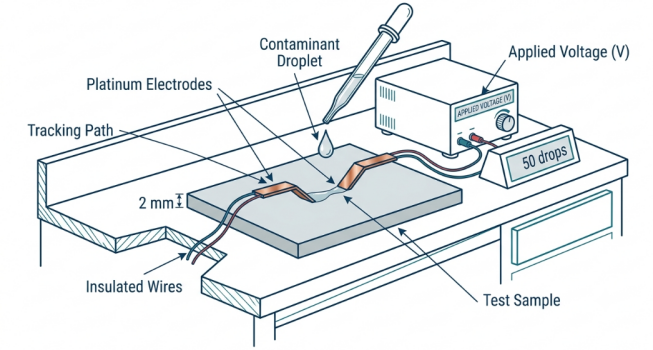
The comparative tracking index (CTI) is the highest voltage (in volts) an insulating material can withstand across its surface before a conductive carbonized path is formed under a contaminated, wet condition. In other words, it indicates the resistance of the laminate surface to tracking when dirt and moisture are involved. The test is according to the IEC 60112 international standard method. Two Platinum electrodes are placed on the surface of the material, and the voltage is applied by the electrodes. A conductive solution (ammonium chloride) is then dropped between the electrodes at specific intervals. The voltage is raised until the material withstands 50 drops without tracking failure, and the surviving voltage is the CTI rating. Here are a few tips to keep in mind:
- CTI is always measured in volts; the higher the CTI, the better the tracking resistance.
- The test purposefully makes use of contamination and moisture, as this is when tracking actually occurs in the field.
- The PTI (proof tracking index) shows that a material will pass at a fixed voltage, not where it has a maximum.
The Role of CTI in Preventing Electrical Breakdown
There are two very different ways a high-voltage gap can fail. First is the clean air arc that clearance distance controls. The second is much sneakier: surface tracking - the contamination slowly deteriorates the surface of the insulator until a permanent conductive path of carbon forms. Tracking doesn't require a large air gap to jump. It is a creep that feeds on humidity, dust, flux residue, and electric field, and once the carbon path is formed, it is permanent and conductive. This is what CTI exists to avoid.
A material that has a high CTI will not carbonize and allow for conductors to be placed closer together on the surface without inviting a tracking failure. That is why CTI meets all safety requirements for mains equipment, mains power supplies, and motor power drives. It is the characteristic that prevents a dusty, damp enclosure from gradually converting your insulating material into a conductor.
How CTI Value Affects PCB Safety and Reliability
Relationship with Creepage Distance and Insulation Design
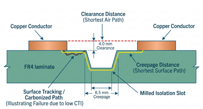
The shortest distance between two conductors along the surface of the insulating material is called creepage, and the shortest distance through air is called clearance. This is the surface along which tracking occurs, and the dimension CTI controls is creepage. The important relationship is this: the higher the CTI material, the lower the creepage distance for a particular working voltage and pollution level; the lower the CTI material, the greater the distance between conductors for a particular working voltage and pollution level. This is directly incorporated into the tables of the safety standards via material groups:
- Material Group I: CTI ≥ 600 V
- Material Group II: 400 ≤ CTI < 600 V
- Material Group IIIa: 175 ≤ CTI < 400 V
- Material Group IIIb: 100 ≤ CTI < 175 V
The level of pollution is equally important. The common assumption is that Pollution Degree 2 (typical indoor, office-grade environments) and Pollution Degree 3 (industrial, conductive dust, condensation) require significantly greater creepage. In standards such as IEC 62368-1 and IEC 60664-1, the required creepage is read from a table which is indexed by working voltage, pollution degree, and material group. Make the material group better, and you can actually close the gap.
Impact on High-Voltage Applications and Regulatory Compliance
However, this is not really significant with low-voltage logic boards. However, once the mains voltage is reached, the CTI value in PCB design turns into a gatekeeper for off-line power conversion, EV charging, solar inverter, and industrial motor drives. Here, the safety agencies aren't leaving much to guesswork. Your creepage distances will have to be justified using the documented material group of your laminate and will be questioned by reviewers for a UL, CE, or IEC mark. Your spacing argument goes out the window if your fabricator does not have proof of the CTI rating of the base material. Think about what is affected the most:
- Off-line AC-DC supplies (with primary side conductors at rectified mains level).
- High voltage plus dirty, vibrating environment EV and industrial chargers.
- High DC bus voltage, long outdoor life photovoltaic inverters.
- Conductive dust and moisture (Pollution Degree 3) on motor drives and HVAC controls.
Common CTI Values Across Different PCB Materials
Standard FR4 and High-CTI Alternatives
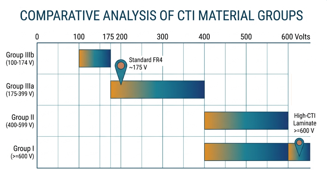
The bad news about regular FR4 is that the majority of common grades fall into Material Group IIIa with a CTI of approximately 175 V. This is OK for many low voltage applications, but is on the light side for spacing high voltage because this is the largest spacing required in the table. For when you have to do better, fabricators can supply high CTI laminates, specially created for tracking resistance, which can achieve CTI ≥ 600 V, qualifying them as Material Group I. These are made with modified resin systems and fillers that have a much higher resistance to surface carbonation as compared to standard epoxy. The table below shows the comparison of typical CTI values and the material group of PCBs.
| Material | Typical CTI (V) | Material Group | Best Fit |
|---|---|---|---|
| Standard FR4 | ~175 | IIIa | Low-voltage digital, general use |
| Mid-grade FR4 | 200-400 | IIIa / II | Moderate voltage, controlled environment |
| High-CTI FR4 | 400-599 | II | Mains power, compact spacing |
| Premium high-CTI FR4 | ≥ 600 | I | High-voltage, Pollution Degree 3, certified products |
| Ceramic / specialty | ≥ 600 | I | Extreme HV and harsh environments |
There are a couple of things to note. Standard FR4 is available everywhere at a low cost, but requires lots of space at high voltages. Uprating to Group II or Group I can significantly reduce your required creepage, and may be worth the effort in terms of board space in a dense design.
Matching CTI to Voltage Levels and Environmental Conditions
No single value of CTI is "correct". Depending on your working voltage, pollution level, and available board space, the right choice will be selected. Overspecifying costs and underspecifying may result in a tracking failure or a certification rejection. To match materials to mission, use these rules of thumb:
- Low voltage (< 50 V), clean environment: Standard FR4 (Group IIIa) is acceptable, CTI is rarely a concern.
- Mains voltage, Pollution Degree 2, generous spacing available: Standard or mid-grade FR4 can be used if the creepage tables say so.
- Compact design, mains voltage: step up to Group II or Group I high-CTI material for legally shrinkable creepage.
- Pollution Degree 3 (industrial, outdoor, dusty): Use Group I (CTI ≥ 600) to maintain a manageable spacing.
- High DC bus or safety critical: Group I material with conservative spacing for field reliability and margin.
Design and Manufacturing Strategies for High CTI Performance
Material Selection and Layout Optimization
Always choose the material group that is above your creepage requirements and not just at the minimum. Then, plan for the surface to play to your strengths. The CTI rating is backed up by a good high-voltage layout. Useful layout tricks to increase real-world tracking resistance:
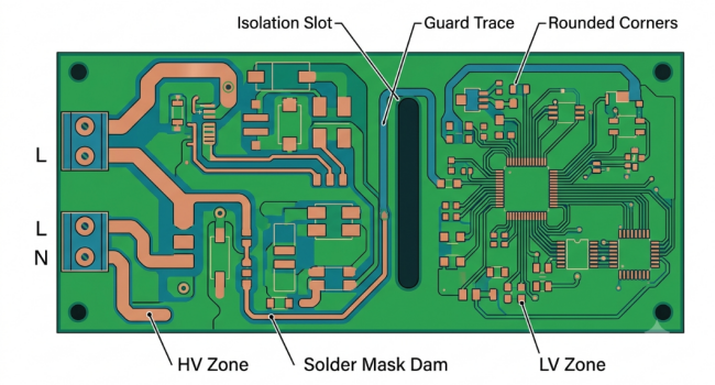
- Isolation slots: Milling a slot between high voltage nets enhances the effective creepage clearance and physically stops a tracking path.
- Solder mask dams and coatings: A continuous mask or conformal coating is used to protect the surface from contamination, but don't always use the mask alone for the full creepage rating.
- Guard traces or grounded barriers: Placing a grounded conductor between hostile nets can intercept surface leakage.
- Smooth/rounded routing: No sharp conductor corners to intensify local fields and promote tracking.
It also helps prevent the presence of flux residue and ionic contamination on high voltage areas since the CTI test simulates that type of contamination. The surface of the board is clean, allowing your selected material group to provide the rated performance.
Process Controls to Maintain CTI Integrity
While the laminate is sold with a guaranteed CTI value, the surface quality can be undermined with improper processing. This is where a disciplined manufacturer steps in, as resistance resides only on the board surface. The key process controls that affect CTI performance:
- Material traceability: The material should be the specified, certified high-CTI laminate, not a substitute, and the material group should be recorded.
- Clean surface preparation: Residual etch chemistry, ionic contamination, or poor cleaning reduces the surface insulation resistance.
- Solder mask application control: Well-cured solder mask with good adhesion and no trapped contaminants.
- Final cleaning and ionic testing: Flux removal after assembly and salts removal by ionic testing maintain the surface as clean as assumed by the CTI test.
JLCPCB's Expertise in High-CTI PCB Production
Wide Selection of Certified High-CTI Materials
Today's PCB manufacturers, such as JLCPCB, carry a wide selection of qualified PCB base materials, including basic FR4 and high CTI materials up to the higher material groups required to support mains voltage and high-voltage designs. With certified options available, you can specify the CTI value for your PCB design to meet your creepage requirement without having to scramble for documentation. When it comes to safety review, that very material data is what safety reviewers will be asking for, and getting it from a fabricator that already has it removes a common certification hurdle out of the way.
To implement these principles, scaling from a prototype (as low as $2) to full volume manufacturing with consistent certified laminate, creepage, and surface integrity is very simple with JLCPCB's fabrication services. Turnkey time as short as 1-2 days, support SMT assembly, the safety foundation you choose is stable from the first article to the mass production.
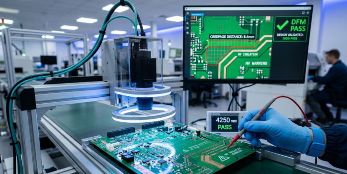
Advanced DFM Support for High-Voltage Designs
Only if spacing is correct, you'll pay for the high-CTI laminate, and this is where the automated design-for-manufacturability (DFM) checks help. JLCPCB's DFM evaluation will help to detect clearance and creepage, catch high-voltage spacing problems early, and identify slot routing issues and mask coverage problems. A standard FR4 layout compared to a high-CTI version can be done early in the design process thanks to instant quoting and EasyEDA integration, before the material group change is expensive and painful. Repeatability is the key measure of any CTI strategy. The prototype board that passes hipot and tracking requirements will have the same safety margin over thousands of units.
Conclusion
The CTI value is a silent protector of high-voltage board safety. It determines the ability of your base material to withstand surface tracking, dictates the creepage distances you need to observe in your board design, and ultimately determines whether your board is eligible for its safety mark. One of the simplest methods to fail a certification that you are certain you have in the bag is to treat it like an afterthought. The better way is to calculate backward: first specify your working voltage and pollution degree, then select the material group that complies with the creepage table with space. With increasing power densities and high-voltage electronics in EVs, solar, and industrial systems, it will become even more relevant to obtain the CTI value right. Choose a material on purpose and partner with a company that is able to prove and manufacture it in a consistent fashion, and high-voltage boards remain safe from the first layer up.
FAQ about CTI Value
Q: What is a CTI value in a PCB?
The CTI value is the comparative tracking index of the laminate, the maximum voltage in volts that the material surface can withstand without forming a conductive carbonized path under wet, contaminated conditions. A higher CTI means better resistance to surface tracking, which is critical for high-voltage boards.
Q: How is the CTI value of a PCB material measured?
It is measured per the IEC 60112 standard, where two platinum electrodes apply voltage across the material surface while an ammonium chloride solution is dripped between them. The voltage that survives 50 drops without tracking becomes the rated CTI value, expressed in volts.
Q: What CTI value does standard FR4 have?
Most standard FR4 grades fall in Material Group IIIa with a CTI value around 175 V. This is adequate for low-voltage work but forces the largest creepage distances in safety tables, so high-voltage designs often need high-CTI laminates rated 600 V or more (Group I).
Q: How does CTI relate to creepage distance?
Creepage is the shortest distance between conductors along the surface, and tracking happens along that surface, so CTI governs it directly. A higher CTI material allows shorter creepage for the same working voltage and pollution degree, letting you build more compact high-voltage layouts safely.
Q: When do I need a high-CTI PCB material?
You need high-CTI material when working with mains voltage, EV charging, solar inverters, or motor drives, especially in dusty or humid Pollution Degree 3 environments. It is also essential when compact spacing or UL, CE, and IEC certification demands that you justify creepage using a documented material group.
Conclusion
Selecting the right CTI value is one of the most critical yet often overlooked decisions in high-voltage PCB design. A proper CTI rating protects your board from surface tracking failures, enables compact layouts, and ensures compliance with strict safety standards such as IEC 62368-1 and UL.
Whether you are designing off-line power supplies, EV chargers, solar inverters, or industrial motor drives, matching your material group (especially Group I with CTI ≥ 600V) to your working voltage and pollution degree can dramatically improve both safety and space efficiency.
At JLCPCB, we provide a wide range of certified high-CTI laminates, professional DFM checks for creepage and clearance, and consistent manufacturing quality from prototype to mass production. Don’t leave your high-voltage design’s safety to chance.
Keep Learning
Your Ultimate Guide to PCB Rulers
In the world of PCB design and manufacturing, having the right tools is crucial for achieving accuracy and precision. One such tool that has gained popularity among professionals and hobbyists is the PCB ruler. This specialized measuring tool is designed to provide accurate measurements, reference information, and component footprints, assisting designers, engineers, technicians, and assemblers in various stages of PCB development. In this guide, we'll explore what a PCB ruler is, the features and mea......
Understanding the Materials Used in PCBs: Selection, Types, and Importance
Key Takeaways FR-4 is the go-to material for most cost-effective and reliable PCBs. Use Rogers for high-frequency and RF applications to reduce signal loss. Higher copper weight (2oz) improves current and heat handling. Choose High-Tg substrates for better thermal stability in multilayer boards. Green LPI soldermask offers the best balance of performance and inspection. Printed circuit boards (PCBs) are an essential component of modern electronics. These boards connect and support electronic component......
How to Select Tg of PCB ?
What is the Tg of PCB? In PCB manufacturing, "Tg" stands for Glass Transition Temperature. It is the temperature at which the PCB substrate material transitions from a rigid, glassy state to a soft, rubbery state. PCBs are flame-retardant (UL94 V-0) and do not burn easily; instead, they soften above Tg. The Critical Correlation Between Tg and Z-Axis CTE (Coefficient of Thermal Expansion) When the temperature exceeds the Tg point, the PCB substrate material (such as standard FR-4) undergoes a physical ......
How to Choose the Thickness of PCB
First, In the world of electronic products, the PCB is often referred to as the "heart" of the device. It interconnects all components, making board thickness one of the most important parameters. Choosing the right PCB thickness directly affects the electrical performance, mechanical stability, thermal management, and long-term reliability of the final electronic product. The process of selecting PCB thickness is influenced by various factors, such as product application scenarios, board material, an......
PCB Copper Pour Basics
What is Copper Pour in PCB Design? Copper pour refers to the technique of filling unused areas of a PCB's copper layers with solid copper planes. These planes are connected to power or ground nets, creating a continuous conductive path. Copper pour is typically used in the power and ground planes, as well as in signal layers for specific purposes. Purpose and Benefits of Copper Pour: Copper pour is primarily used to fill unused areas on PCB copper layers with solid (or hatched) copper connected to pow......
How to Prevent Solder Bridges for Superior PCB Quality and Reliability
Key Takeaways Solder bridges are a leading cause of SMT failures on fine-pitch components. Prevent them with proper solder mask dams (0.075–0.1mm), optimized stencil design, and controlled reflow profiles. Combine good DFM practices with AOI + X-ray inspection for maximum reliability. Professional manufacturing and early DFM review significantly boost first-pass yield and reduce costly rework. You have experienced the post-reflow sadness and eyed the board that failed on the first reflow, if you have ......