How to Solder SMD LEDs: A Step-by-Step Guide for Iron, Hot Air, and Reflow
15 min
- Quick Answer: How Do You Solder an SMD LED?
- What You Need: Tools & Materials
- Step 1: Check SMD LED Orientation & Polarity
- Step 2: How to Solder a Single SMD LED with an Iron
- Which SMD LED Soldering Method Should You Use?
- How to Solder SMD LEDs with Hot Air
- How to Solder SMD LEDs with Reflow
- Soldering SMD LED Strips and Boards with Many LEDs
- How to Avoid Heat Damage to SMD LEDs
- Common SMD LED Soldering Problems and How to Fix Them
- FAQ about Soldering SMD LEDs
- Conclusion: How to Solder SMD LEDs Successfull
Key Takeaways
Confirm polarity and orientation first: Identify the anode and cathode before applying any heat, because a reversed SMD LED will not light and correcting it costs another thermal cycle.
Match the method to the job: A fine-tip iron suits one or a few LEDs, hot air is best for rework and single-part replacement, and solder paste with reflow is fastest for complete boards.
Keep solder and heat minimal: A small, fully wetted fillet and short dwell times protect the LED die, phosphor, and encapsulant from heat damage.
Scale with a stencil: For boards with many LEDs, a stencil delivers consistent paste deposits and makes assembly faster and more repeatable than hand soldering every part.
SMD LEDs look simple, but their small size makes them less forgiving than through-hole LEDs. They are polarity-sensitive, easy to shift on tiny pads, and vulnerable to excessive heat. The good news is that learning how to solder SMD LED parts is straightforward once you choose the right method and keep each heating step brief.
This guide covers three practical approaches: a soldering iron for one or a few LEDs, hot air for small batches and rework, and reflow for complete boards. It also explains LED strip soldering, heat-damage prevention, and common problems that can occur after assembly.
Quick Answer: How Do You Solder an SMD LED?
To solder an SMD LED, first confirm its polarity and orientation, tin one PCB pad, hold the LED with tweezers, and reheat the pad to tack the component in place. Solder the opposite pad, then briefly reheat the first joint if needed. For multiple LEDs, solder paste with hot air or reflow is usually faster and more consistent.
What You Need: Tools & Materials
You do not need a full SMT production bench to hand solder a few LEDs. A few basic, well-maintained tools are enough to make placement easier and reduce the time the LED is exposed to heat.
- Fine-tip, temperature-controlled soldering iron and fine solder wire suitable for electronics.
- Electronics flux, preferably in a pen or syringe. For technique details, see how to apply solder flux when hand soldering.
- Fine anti-static tweezers, strong lighting, and magnification for small packages and subtle orientation marks.
- Isopropyl alcohol (IPA) and lint-free swabs for cleaning compatible flux residues after soldering.
- For higher-volume assembly or component removal, use a hot-air rework station. For assembling a complete LED board, solder paste with a hot plate or reflow oven is more practical. A stencil becomes useful when you need to apply consistent paste deposits across multiple footprints.
Step 1: Check SMD LED Orientation & Polarity
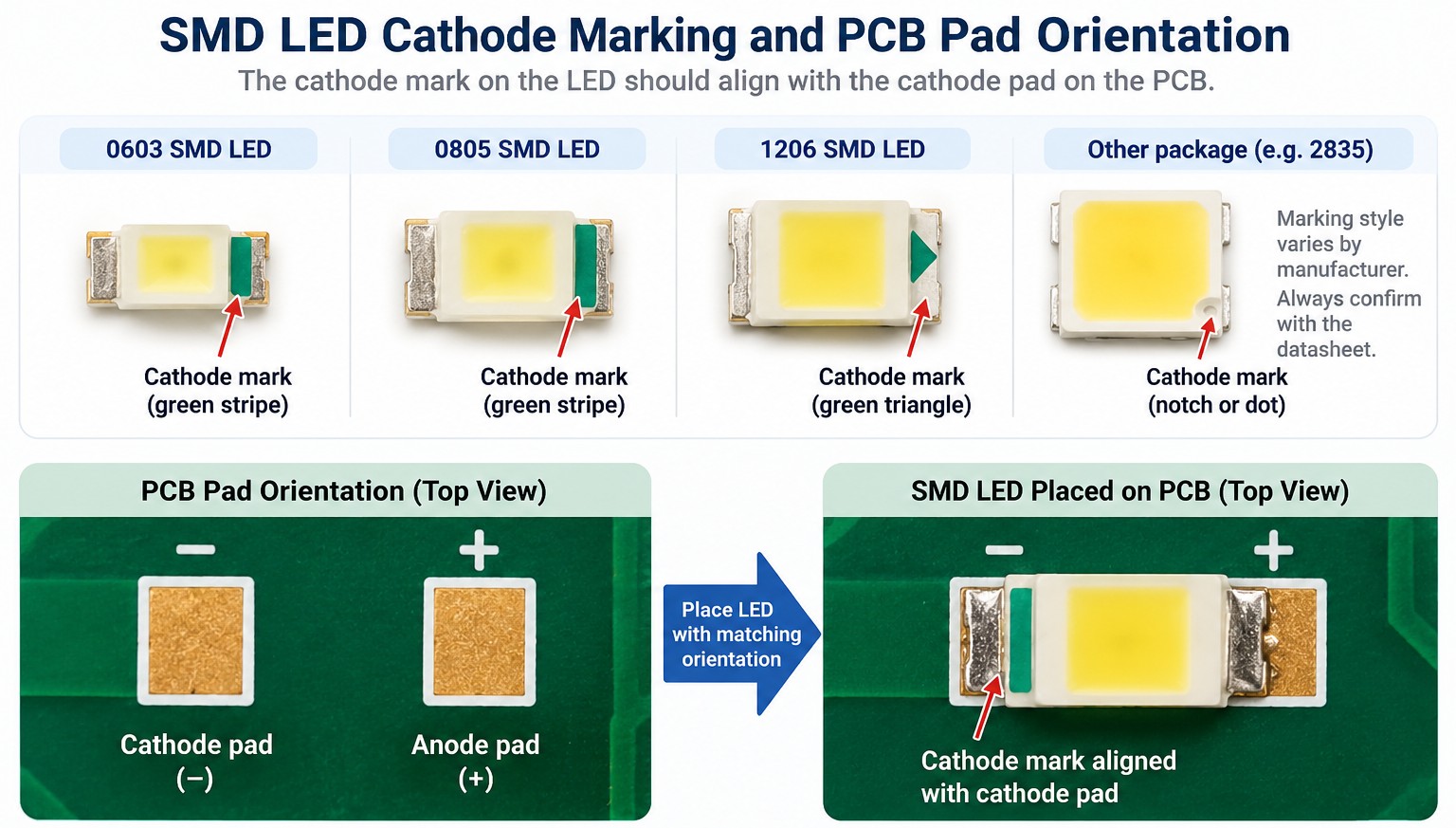
Before applying heat, confirm which pad is the anode and which is the cathode. A reversed LED will not illuminate, and correcting it later means another heating cycle that can damage the package or lift a small PCB pad.
Do not rely on one universal package mark. LED manufacturers use different dots, notches, bars, internal electrode shapes, and package drawings. Match the marking to the PCB footprint and the component datasheet. If the marking is unclear, a multimeter in diode mode can provide a quick orientation check on many visible LEDs. For a full marking guide, see how to identify SMD LED polarity and confirm the symbol against the part datasheet.
Step 2: How to Solder a Single SMD LED with an Iron
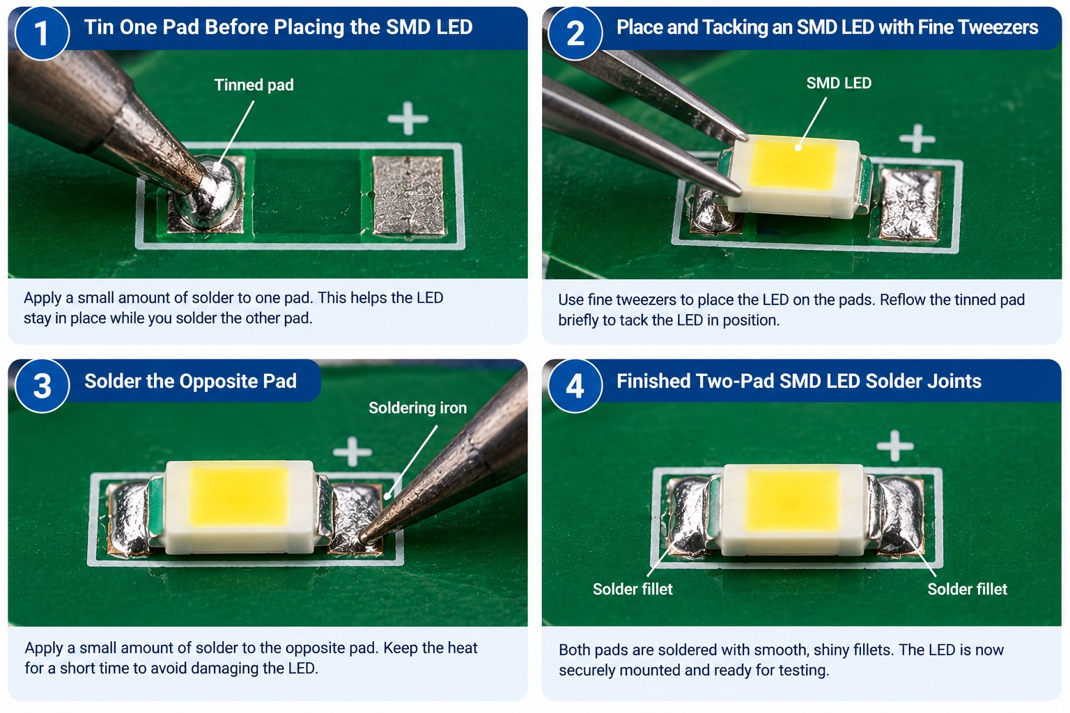
For one LED or a short prototype run, a fine-tip iron is usually the quickest method. The key is to anchor the component on one pad first, then finish the second joint without repeatedly heating both sides.
Tin one pad
Add flux, then melt only a small amount of solder onto one PCB pad. A low mound is enough; too much solder can make the LED sit at an angle.
Place the LED
Hold it with fine tweezers in the correct orientation and rest one termination on the tinned pad. Keep the package centered over both lands.
Tack the first side
Touch the iron to the tinned pad until the solder flows and the LED settles flat. Remove the iron, keep the tweezers still, and let the joint solidify.
Solder the second pad
Apply a little flux if needed, heat the pad and LED termination together, and feed a small amount of solder until it wets both surfaces.
Reflow the first pad briefly
Touch the original joint again only long enough to correct its shape and confirm the LED is sitting flat. Avoid unnecessary repeated heating.
Inspect and clean
Look for smooth, well-wetted fillets, no bridges, and a flat component body. Lead-free joints may look less shiny than tin-lead joints. Clean compatible flux residue with IPA if required.
If you need broader hand-soldering fundamentals beyond LEDs, use the SMD component soldering guide rather than repeating the general technique here.
Which SMD LED Soldering Method Should You Use?
Choose the method mainly by LED count, package size, and whether you are building or repairing. An iron gives direct control for a few parts. Hot air heats both terminals simultaneously and is useful for replacing individual LEDs. Reflow scales best when dozens or hundreds of LEDs share similar footprints.
| Soldering Iron | Hot Air | Reflow (Hot Plate/Oven) | |
|---|---|---|---|
| Best for | One or a few LEDs | A few LEDs, rework, removal | Whole boards and many LEDs |
| Speed for many LEDs | Slow | Medium | Fast |
| Tools needed | Iron, solder, flux, tweezers | Hot-air station, paste/flux, tweezers | Paste, hot plate/oven; stencil for boards |
| Tiny / fine-pitch LEDs | Possible but difficult | Good with controlled airflow | Best for repeated small footprints |
| Heat control | Direct and local; operator-dependent | Local convection; watch airflow and dwell | Profile-controlled and uniform; heats whole board |
How to Solder SMD LEDs with Hot Air
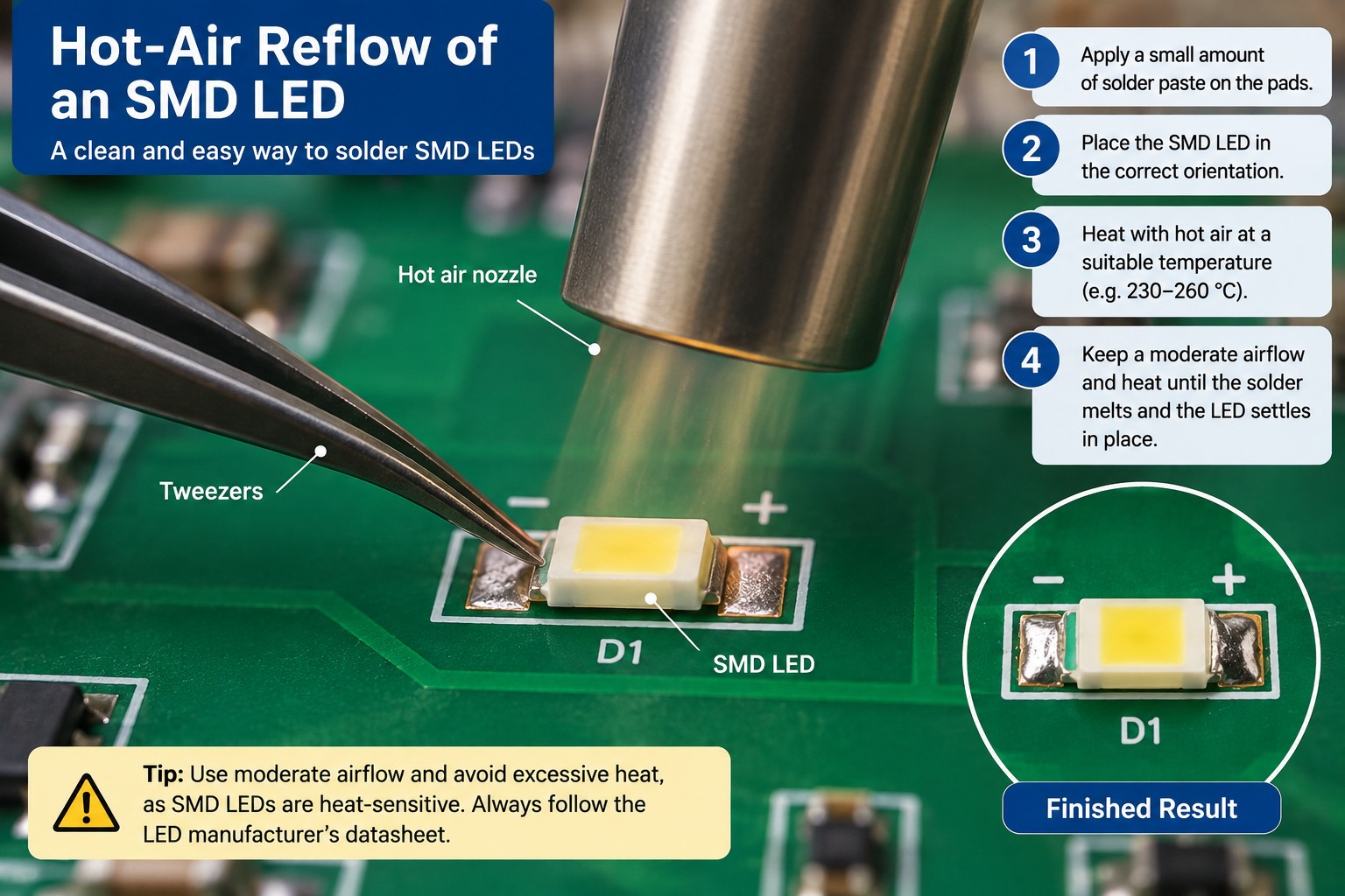
To solder SMD LEDs with hot air, apply a small amount of solder paste to the pads, place the LED in the correct orientation, and heat the area until the solder reflows and the component self-centers. When replacing a single failed LED, you can also lightly tin both pads instead of using solder paste.
Use moderate airflow. Small LEDs can move, rotate, or be blown out of position if the air jet is too strong. Heat the board and pads rather than aiming directly at the LED lens, and stop heating once both solder joints have fully reflowed. The appropriate nozzle temperature and dwell time depend on the LED, solder alloy, board copper, and station calibration, so check the component datasheet rather than treating one station setting as universally safe.
For nozzle selection, board preheating, airflow control, and general rework technique, see the hot air surface-mount soldering guide.
How to Solder SMD LEDs with Reflow
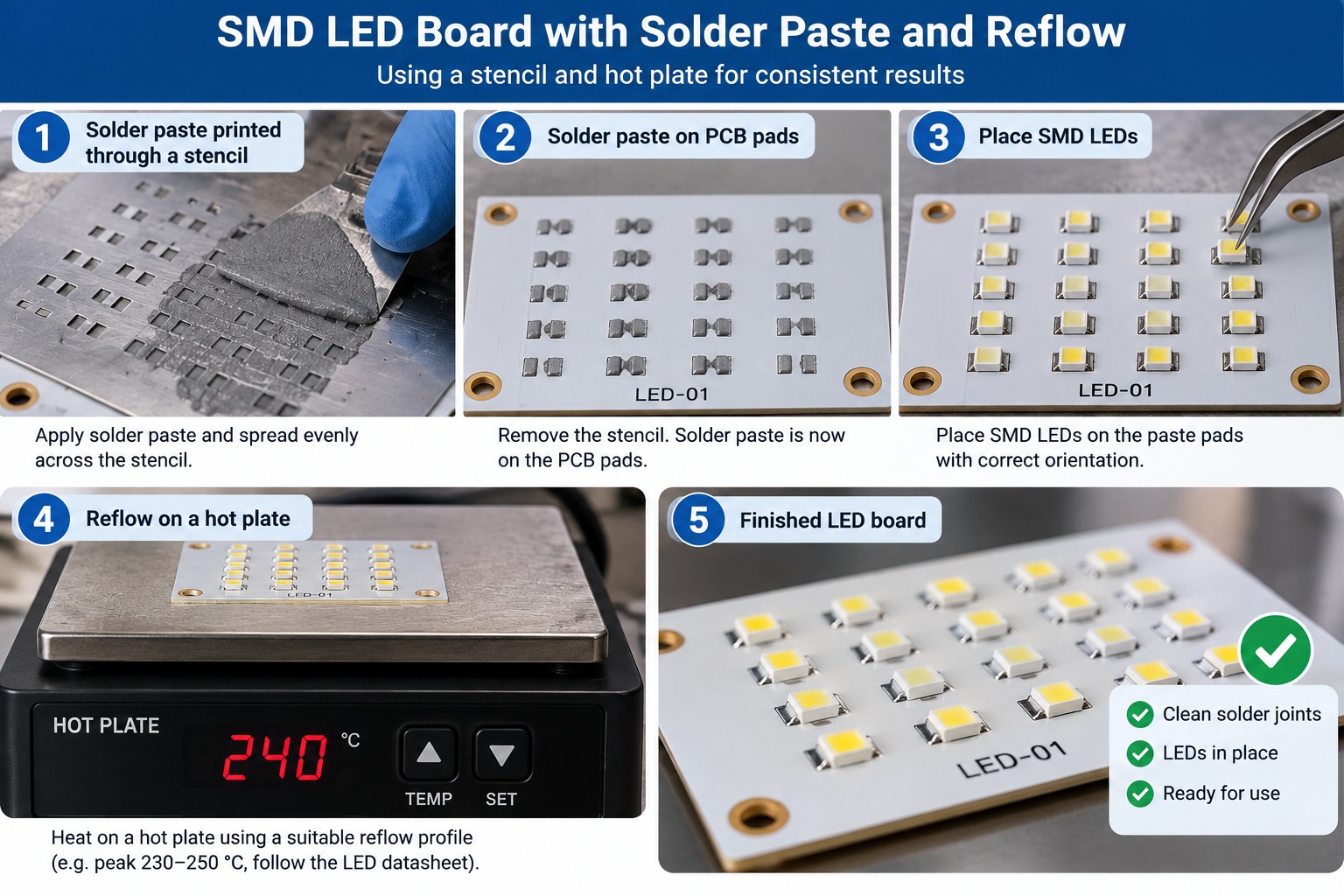
For a full LED board, reflow is normally the cleanest and most repeatable method. Print or dispense solder paste, place each LED in the correct orientation, and heat the assembly on a controlled hot plate or in a reflow oven. Both terminals are heated as part of the same thermal cycle, helping each component receive more consistent heating.
The LED datasheet controls the limit. As one manufacturer example, a current Nichia SMD LED specification allows a lead-free reflow peak of up to 260 °C for a limited time and states that reflow should not be repeated more than twice. That figure is not a universal recipe; other LEDs, lenses, phosphors, and solder systems may require different limits. See a representative Nichia SMD LED soldering specification for a manufacturer-specific example.
Use the LED manufacturer's reflow curve as the starting point, then verify the actual board profile. Large copper areas, metal-core PCBs, and mixed component sizes can change how quickly an LED package heats. If you need the complete hot-plate and stencil process, use the dedicated reflow guide rather than extending LED-specific handling into a general reflow tutorial. For the complete process, see reflow soldering at home with a hot plate and stencil.
For production context, the Nichia LED Mounting Process Techniques application note also emphasizes using the applicable LED specification when setting the reflow conditions.
Soldering SMD LED Strips and Boards with Many LEDs
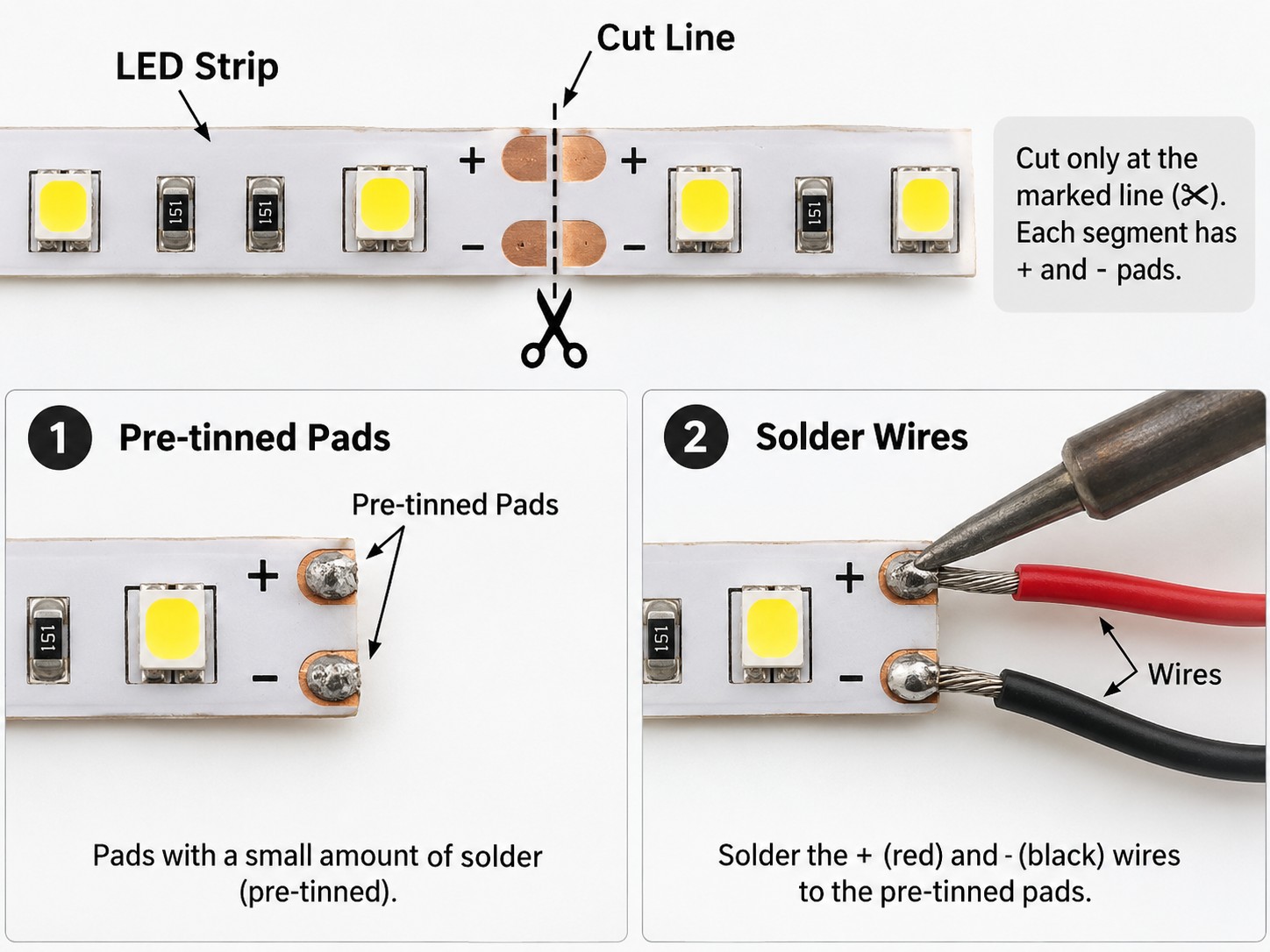
LED strip soldering needs a different touch because the copper pads sit on a thin flexible substrate. Cut the strip only at the marked cut line, expose clean pads, and pre-tin both the strip pads and the wires. Bring the tinned surfaces together and heat only long enough for the solder to join.
If you need to solder LED strip connections repeatedly, secure the strip so the joint is not under cable tension while hot. Excessive dwell time can soften the flexible backing or lift a copper pad. Use a small iron tip, flux, and strain relief rather than adding more solder to make the connection appear stronger.
Boards with many SMD LEDs are where a stencil becomes genuinely useful. A stencil is especially useful when you need to assemble multiple boards or apply solder paste to many small LED footprints consistently. It bridges the gap between manual soldering and repeatable paste-and-reflow assembly. Hand soldering every LED is slow and gives each component a different temperature. Printing a controlled paste deposit across the board, placing all LEDs, and reflowing once gives more consistent joint volume and usually less total handling. Clean paste release is especially important on small two-pad LED footprints. A worked many-LED example is the 8x8 RGB LED matrix build.
How to Avoid Heat Damage to SMD LEDs
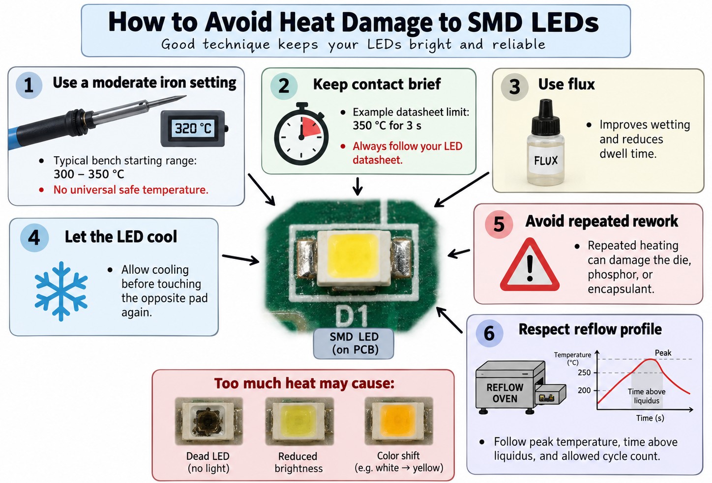
SMD LEDs convert electrical energy into light inside a small semiconductor package, and their optical structures can be sensitive to heat. Excessive temperature or prolonged dwell time can damage the die, bond structures, encapsulant, or phosphor. The result may be a failed LED, reduced brightness, or a visible color shift.
For hand soldering, use a moderate iron setting and work quickly. Many electronics workstations operate in the 300–350 °C range for hand soldering, but there is no universal safe temperature. For example, some Nichia SMD LED datasheets specify a maximum hand-soldering condition of 350 °C for 3 seconds. Treat the limit in the datasheet for your specific LED as the controlling value. The exact limits vary by package, so verify the manufacturer soldering conditions for the LED you use.
Use flux to shorten the time needed to achieve wetting, and let the LED cool before touching the opposite pad again. Avoid repeated rework on the same component. With reflow, follow the specified peak temperature, time-above-liquidus limits, and allowed cycle count instead of increasing the oven peak to compensate for poor paste printing or insufficient preheat.
For production assembly, IPC J-STD-001 provides requirements for soldered electrical and electronic assemblies.
IPC-A-610 is the companion acceptability standard used to evaluate finished electronic assemblies.
Common SMD LED Soldering Problems and How to Fix Them
| Problem | How to Fix | |
|---|---|---|
| 1 | LED does not light | If the SMD LED does not light after soldering, recheck the cathode orientation against the PCB and test a spare LED in diode mode. |
| 2 | Tombstoning | Small LED stands up on one end (tombstoning). Uneven heating or unequal solder volume can pull the component upright. Reflow both pads evenly, reduce excess solder on the pre-tinned pad, and keep the two deposits similar. |
| 3 | Solder bridge | Solder bridge forms between the two pads. Add flux, clean the iron tip, and drag the excess solder away from the gap. If needed, use fine solder wick. On tiny LED footprints, a very small solder volume is enough. |
| 4 | Dull or grainy joint | Joint looks dull or grainy. The solder may not have fully wetted, or the component moved as it cooled. Add flux, reheat the joint until it flows properly, then hold the LED still until the solder solidifies. |
| 5 | LED is dim or wrong color | LED becomes dim or changes color after soldering. Heat may have damaged the die, phosphor, or encapsulant. Replace the LED and reduce contact time or reflow peak on the next attempt. Confirm the datasheet limits before repeating the process. |
| 6 | Lifted LED-strip pad | Pad lifts from an LED strip. Too much heat or mechanical pull can separate the copper from the flexible backing. Stop heating, avoid pulling the wire, and move to an undamaged cut section if the pad cannot be repaired reliably. |
For the root causes of unequal wetting and heating, see the PCB tombstone guide.
FAQ about Soldering SMD LEDs
Q: Can You Hand Solder 0402 or 0603 SMD LEDs?
Yes, 0603 LEDs are practical to hand solder with magnification, fine tweezers, and a small tip; 0402 parts are possible but much less forgiving. The smaller the package, the easier it is to bridge pads, lose orientation, or move the LED while the solder is liquid. For several 0402 LEDs, paste plus reflow is usually faster and more repeatable than soldering each one individually.
Q: What Solder Wire Diameter Is Best for SMD LEDs?
Fine solder wire gives better control because a two-pad LED needs very little alloy. Around 0.3–0.5 mm wire is convenient for small SMD work, although larger wire can still be used if you feed it sparingly. The goal is not to fill the pad with solder; it is to create a thin, fully wetted fillet. Flux often improves control more than changing wire diameter.
Q: Is Leaded or Lead-Free Solder Better for SMD LED Soldering?
Both can produce reliable SMD LED joints when used with the appropriate process. Tin-lead solder generally melts at a lower temperature and can be easier to hand solder, while lead-free alloys are common in commercial RoHS-compliant products and typically require higher process temperatures. Do not mix process assumptions: use the solder alloy, flux, tip temperature, and reflow profile that match your product requirements.
Q: Can You Use a Household Heat Gun Instead of a Hot-Air Station?
A household heat gun is not a good substitute for controlled SMD rework. Its airflow is usually too strong and the heated area too large, making it easy to blow away tiny LEDs or overheat nearby plastics and components. A hot-air rework station provides a smaller nozzle, adjustable airflow, and better temperature control. For occasional assembly, a soldering iron is safer than improvising with a general-purpose heat gun.
Q: How Do You Desolder an SMD LED Without Lifting the Pads?
Heat both LED pads as evenly as possible and remove the component only after the solder on both sides is molten. Hot air is convenient because it warms both terminals together; with an iron, adding fresh solder can help create enough thermal contact before lifting with tweezers. Never pry against a solid joint. After removal, wick excess solder gently and let the PCB cool before installing the replacement.
Q: Does an SMD LED Need Preheating Before Hand Soldering?
Usually not for a small two-pad LED on a normal FR-4 board, but board preheating can help when a large ground plane, metal-core PCB, or heavy copper layer pulls heat away from the joint. Preheat the board, not the LED package, and keep the temperature controlled. The purpose is to reduce the temperature difference and iron dwell, not to add another uncontrolled heating step.
Q: Why Does an LED Test Good but Not Work After It Is Soldered?
A good diode-mode test does not guarantee the assembled circuit is correct. Check LED orientation, pad continuity, solder bridges, the current-limiting resistor, supply voltage, and whether the driver is actually enabled. Also inspect for a joint that looks connected but has not wetted the termination. If another LED works in the same footprint, the original part may have suffered heat or mechanical damage during assembly.
Q: How Much Solder Paste Should You Put on SMD LED Pads?
Use enough paste to cover the intended pad area with a thin, controlled deposit rather than a large blob. Too much paste can float the package, bridge the two pads, or increase tombstoning risk; too little can leave an open or weak joint. For a full LED board, a correctly designed stencil is the easiest way to repeat the same paste volume across every footprint.
Conclusion: How to Solder SMD LEDs Successfull
Successful SMD LED soldering comes down to three fundamentals: confirm orientation before heating, use only the solder volume you need, and keep thermal exposure under control. For one or a few LEDs, tin-place-tack-solder with an iron is efficient. Hot air is useful for replacement, while solder paste and reflow become more practical as the LED count grows.
If you are learning how to solder SMD LED boards for a larger project, scale the process instead of repeating the same hand operation hundreds of times. A well-matched PCB footprint, controlled paste deposit, stencil, and reflow cycle can make a full LED matrix or light board faster to assemble and more consistent to inspect.
Keep Learning
How to Solder SMD LEDs: A Step-by-Step Guide for Iron, Hot Air, and Reflow
Key Takeaways Confirm polarity and orientation first: Identify the anode and cathode before applying any heat, because a reversed SMD LED will not light and correcting it costs another thermal cycle. Match the method to the job: A fine-tip iron suits one or a few LEDs, hot air is best for rework and single-part replacement, and solder paste with reflow is fastest for complete boards. Keep solder and heat minimal: A small, fully wetted fillet and short dwell times protect the LED die, phosphor, and enc......
How to Solder a Potentiometer (PCB, Panel & Guitar Pots)
Key Takeaways Identify the wiper terminal: In most potentiometers, the middle pin is the wiper. Always verify with a multimeter before soldering. Pre-tin surfaces: Tin both the terminals and wires before joining to ensure strong, clean solder joints. Control heat carefully: Use a temperature-controlled iron and keep contact time short (below 260°C for a few seconds) to avoid damaging the internal resistive track. Test after soldering: Always check continuity and sweep the shaft while measuring output ......
How to Solder QFN Components: A Step-by-Step Guide
Key Takeaways A solder paste stencil is the most reliable way to achieve consistent QFN solder joints. Always use a window-pane paste pattern on the center thermal pad instead of one large paste deposit. Control solder paste volume to prevent floating, bridging, and excessive voiding. Reflow needs a proper soak-then-reflow-then-cool profile Hand soldering is practical only for certain QFN packages and usually cannot solder the center thermal pad effectively. Because QFN solder joints are hidden beneat......
How to Solder Pin Headers: A Step-by-Step Guide
Key Takeaways Breadboard or jig: Use a breadboard or jig to hold the header pin square while you work. Tack one pin first: Check alignment before soldering the rest. Keep heat brief: So the plastic housing doesn't melt. Cut breakaway strips: Score the plastic between pins, not by forcing a cut mid-pin. SMD headers: Soldered with paste and reflow rather than through-hole technique. Desolder a pin: Add fresh solder plus wick or a pump, or use hot air. Introduction You solder a header pin, look at it, an......
Hot Air Surface Mount Soldering: A Step-by-Step Guide
Key Takeaways Heat Control Is Everything: Hot air SMD soldering delivers uniform heat across all pads simultaneously, eliminating the lifted pads and cold joints common with iron-based soldering of fine-pitch components. Airflow Kills Small Parts: Set airflow to just 10–20% for 0402/0201 passives to avoid the Bernoulli Effect that turns tiny resistors into projectiles. Stencil Precision Prevents Tombstoning: A precision-cut SMT stencil deposits equal paste volume on both pads, balancing surface tensio......
Solder Bridging: Preventing a Common PCB Soldering Defect
Modern electronics demand compact PCB layouts with dense pad spacing and miniature components. Engineers deploy 0201 packages, fine pitch QFN devices, and large BGA arrays across SMT assembly lines. These layout conditions increase complexity during reflow soldering and raise the probability of PCB soldering defects. Solder bridging appears frequently within high-density boards that contain narrow pad spacing and large solder paste deposits. A solder bridge forms an unintended conductive path between ......