
Build a Professional 8x8 RGB LED Matrix with JLCPCB
6 min
- Project Overview
- How the WS2812B LED Matrix Works
- Design Process in KiCad
- The JLCPCB Solution
- Testing & Results
- How to Build Your Own 8x8 RGB LED Matrix
- Final Thoughts
- FAQs
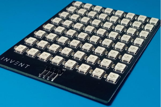
In the world of DIY electronics, building a clean, reliable 8×8 RGB LED matrix used to mean hours of painstaking hand-soldering — 64 WS2812B LEDs plus 64 decoupling capacitors. That all changed when maker Lucas Fernando designed a fully custom PCB from scratch and had it professionally assembled by JLCPCB on his very first try.
The result? Five perfectly finished, ready-to-use 8×8 addressable LED matrices that look like commercial products. Best of all, the entire project is 100% open-source. You can download the Gerber files, BOM, CPL, schematics, and test code from GitHub and order your own boards with JLCPCB in minutes.Project Files (ready for direct JLCPCB upload):
GitHub Repository – Gerber zip, BOM.csv, CPL.csv, Schematics PDF & Code
Project Overview
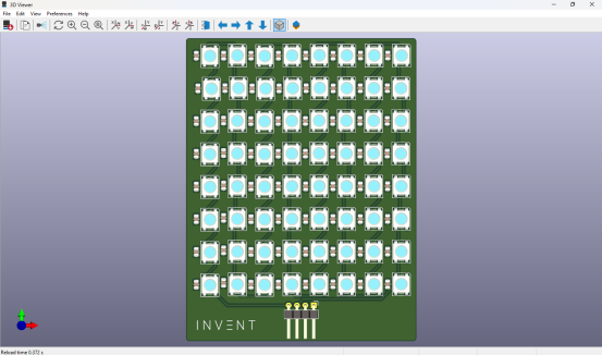
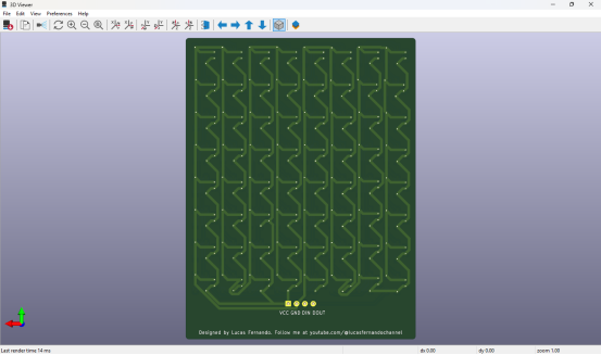
This modular 8×8 RGB LED matrix uses 64 individually addressable WS2812B LEDs arranged in a perfect grid. Each LED is paired with a 100nF ceramic capacitor for power stability, and the board includes a convenient right-angle 4-pin connector (5V / GND / DIN / DOUT) that makes daisy-chaining multiple panels effortless.
“Today I want to share a project I’m genuinely proud of: an 8×8 RGB LED matrix that I designed completely from scratch and had professionally assembled in a real factory,” said Lucas Fernando. “And here’s the coolest part — you can chain multiple modules together and control them as if they were a single massive display.”
How the WS2812B LED Matrix Works
The magic lies in the WS2812B — a smart LED with a tiny integrated circuit inside each package. It requires only one data line to control color and brightness independently for every pixel.
Data travels in a daisy-chain:
-The microcontroller sends a long stream of bits.
-Each LED reads the first 24 bits meant for it (8-bit RGB).
-It then forwards the rest through the DOUT pin to the next LED.
Libraries like Adafruit NeoPixel handle all the complex NZR timing, making control extremely simple on Arduino, ESP32, Raspberry Pi, or any compatible board.
Why one 100nF capacitor per LED?
WS2812B LEDs generate current spikes when switching colors. Without local decoupling, you get flickering, data glitches, or reduced reliability. A 100nF capacitor placed right next to each LED is the industry-standard solution.
No external current-limiting resistors are needed — the WS2812B has built-in regulation.
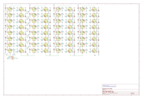
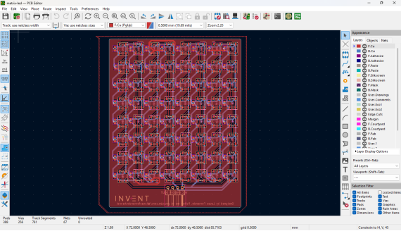
Design Process in KiCad
The board was designed in KiCad with modularity and manufacturability in mind:
· 2-layer FR-4 PCB
· Black solder mask for a premium look
· Power traces: 0.8 mm (safe for ~2A)
· Data lines: 0.3 mm
· Right-angle 4-pin header for clean cabling
Critical Power Warning
At full brightness white, 64 LEDs can draw up to 4A. The PCB is safely designed for ~2A maximum (or 50% brightness). Always use an external stable 5V power supply and share ground with your microcontroller. Never power it directly from an Arduino 5V pin except for very low-brightness testing.
The JLCPCB Solution
This was Lucas’s first time ordering professional PCB assembly. Hand-soldering 128 tiny components was out of the question.The JLCPCB process was incredibly smooth:
1. Upload the Gerber zip file and choose 2-layer black PCB.
2. Enable PCBA service (top side only).
3. Upload BOM.csv and CPL.csv files.
4. JLCPCB’s system instantly matches components from its vast in-stock library (WS2812B-HS01/W and 100nF capacitors were readily available).
5. Review the interactive 3D preview and place the order.
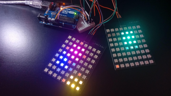
A few days later, five fully assembled boards arrived.
“The PCBs looked clean and professional — perfectly aligned LEDs, shiny solder joints, and no messy flux residue. It no longer looked like a hobby project, but a real product,” Lucas reported. “I was nervous because it was my first factory-assembled board, but the quality exceeded all expectations.”
Testing & Results
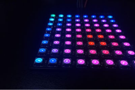
Connecting the first board to an Arduino Uno and uploading the provided animations.ino sketch produced instant success. Every LED lit perfectly with zero dead pixels or flickering.
The included animations (color wipe, smooth rainbow, wave effects, sparkle, solid colors) are both beautiful and practical diagnostic tools. Daisy-chaining two boards worked flawlessly — the system behaved as one continuous large panel, exactly as designed.
How to Build Your Own 8x8 RGB LED Matrix
· Download all files from the GitHub repository.
· Go to jlcpcb.com, upload the Gerber zip.
· Select 2-layer, black solder mask, and enable PCBA.
· Upload BOM and CPL files — components auto-match.
· Review 3D preview and order.
· Receive professional boards in days.
· Connect to Arduino/ESP32, upload code, and enjoy!
Project Specifications
· LEDs: 64 × WS2812B (LCSC C22371521)
· Decoupling: 64 × 100nF capacitors (LCSC C49678)
· Connector: 1 × right-angle 4-pin header (LCSC C91552)
· Layers: 2
· Finish: HASL (or ENIG optional)
· Power: 5V, ≤2A recommended (50% brightness)
· Control: Single data line, Adafruit NeoPixel library compatible
· License: GPL-3.0 (fully open-source)
Final Thoughts
This project proves that professional-grade hardware is now within reach for every maker. What used to require expert soldering skills can now be achieved by anyone with a solid design and JLCPCB’s reliable service.
Whether you want one beautiful matrix, a giant LED wall, or a base for your next creative invention, this open-source design is the perfect starting point.
Ready to build your next project?
Get an instant quote for PCB + PCBA at JLCPCB today!All files are free to download, modify, and use. Go invent something amazing — you can do it!

FAQs
Q1: Why choose JLCPCB PCBA over hand-soldering?
Hand-soldering 128 tiny parts is time-consuming and error-prone. JLCPCB’s automated SMT delivers perfect alignment and near-100% yield.
Q2: How many matrices can be daisy-chained?
Theoretically unlimited (limited by power and refresh rate). Two or four boards work flawlessly in testing.
Q3: What power supply is recommended?
Use an external stable 5V supply rated 2A or higher (5A+ for safety). Never power directly from Arduino 5V pin except low-brightness tests.
Q4: Are the files completely free and open-source?
Yes! All Gerber, BOM, CPL, schematics and code are under GPL-3.0 license — free to download, modify and use commercially.

Popular Articles
• PiBrick Pocket-CM5: A Compact Raspberry Pi CM5 Handheld PC Built with JLCPCB
• From Membrane Frustration to Custom Mechanical Mastery: Taifur's V3 Full Keyboard Project
• Turn Your Raspberry Pi Pico into a Professional JTAG Programmer with DirtyJTAG & OpenFPGALoader
• Premium Portable Speaker Built with 8-Layer PCBs, DSP & Smart Amps
• ESP32 Smart Control Board for Realistic RC Model Automation
Keep Learning
PiBrick Pocket-CM5: A Compact Raspberry Pi CM5 Handheld PC Built with JLCPCB
Key Takeaways The piBrick Pocket-CM5 is a fully functional, smartphone-sized Raspberry Pi CM5 handheld PC with a physical QWERTY keyboard, AMOLED display, and M.2 NVMe SSD The project utilizes JLCPCB's 4-layer PCB fabrication with controlled impedance (90-ohm for USB, 100-ohm for PCIe/MIPI DSI) to maintain signal integrity Designed using EasyEDA and fabricated by JLCPCB, the project was submitted to the EasyEDA Spark program, successfully securing parts and materials sponsorship for its development. J......
From Membrane Frustration to Custom Mechanical Mastery: Taifur's V3 Full Keyboard Project
Note Motivation: Replaced a dust-prone membrane keyboard with a durable, custom DIY alternative. Specs: 87-key TKL layout powered by Raspberry Pi Pico (RP2040), featuring hot-swap support, QMK, OLED, and an encoder. Design: A unique 3-layer PCB stack featuring symmetrical routing, an exposed controller, and visible "diode art". Support: Designed using EasyEDA and fabricated by JLCPcB, the project was submitted to the EasyEDA Spark program successfully securing parts and materials sponsorship for its d......
ESP32 Smart Control Board for Realistic RC Model Automation
Key Takeaways This project demonstrates how a well-designed custom PCB, manufactured and assembled through JLCPCB, can democratize advanced electronics for hobbyists. Key lessons include: Prioritizing compact, high-density layouts while respecting DFM rules. Leveraging professional SMT assembly for complex boards. Designing with clear labeling and modularity for user-friendliness. Choosing a manufacturing partner whose capabilities match your project's needs for consistent results. Project Overview: B......
Premium Portable Speaker Built with 8-Layer PCBs, DSP & Smart Amps
Project Background and Introduction When you unbox a beautifully crafted portable speaker that delivers rich, room-filling sound with crisp highs, deep bass, and intelligent audio processing, it’s easy to imagine it came from a big-name factory. But behind this elegant Harman/Kardon-inspired design lies the story of an innovative maker who turned a personal passion project into a fully functional, high-performance audio system—entirely prototyped and produced with JLCPCB’s PCB and PCBA services. This ......
Turn Your Raspberry Pi Pico into a Professional JTAG Programmer with DirtyJTAG & OpenFPGALoader
In the world of FPGA development, having a reliable, low-cost JTAG programmer used to mean either buying expensive vendor cables or adding high-cost FTDI chips to every board. Maker Khaled Magdy changed that by turning a $4 Raspberry Pi Pico into a fully functional JTAG adapter using DirtyJTAG firmware and OpenFPGALoader — then had his custom FPGA boards professionally assembled by JLCPCB. The entire solution is 100% open-source. You can download the firmware, follow the Windows installation steps, an......
Build a Professional 8x8 RGB LED Matrix with JLCPCB
In the world of DIY electronics, building a clean, reliable 8×8 RGB LED matrix used to mean hours of painstaking hand-soldering — 64 WS2812B LEDs plus 64 decoupling capacitors. That all changed when maker Lucas Fernando designed a fully custom PCB from scratch and had it professionally assembled by JLCPCB on his very first try. The result? Five perfectly finished, ready-to-use 8×8 addressable LED matrices that look like commercial products. Best of all, the entire project is 100% open-source. You can ......