Hot Air Surface Mount Soldering: A Step-by-Step Guide
9 min
- Common Mistakes in Hot Air Surface Mount Soldering
- Essential Tools for Professional Hot Air SMD Work
- Step-by-Step Guide to SMD Soldering With Hot Air
- Why Stencil Precision Is Vital for Hot Air Reflow Soldering
- Optimal Parameters for SMD Soldering With Hot Air
- FAQ about Hot Air Surface Mount Soldering
- Conclusion: Mastering Hot Air Surface Mount Soldering
Key Takeaways
Heat Control Is Everything: Hot air SMD soldering delivers uniform heat across all pads simultaneously, eliminating the lifted pads and cold joints common with iron-based soldering of fine-pitch components.
Airflow Kills Small Parts: Set airflow to just 10–20% for 0402/0201 passives to avoid the Bernoulli Effect that turns tiny resistors into projectiles.
Stencil Precision Prevents Tombstoning: A precision-cut SMT stencil deposits equal paste volume on both pads, balancing surface tension torques during reflow and preventing one-side lift-off.
The Silver Flash Is Your Go Signal: Watch for the moment paste transforms from dull grey to shiny silver — that is peak liquidus. Do not move the board for 30 seconds after.
Preheat Saves Boards: A 60–120 second soak phase activates flux, equalizes thermal mass, and prevents popcorning on FR4 substrates.
Anyone who has ever tried soldering a 0402 resistor or a fine pitch QFN with an iron understands the pain, the lifted pads, the cold joints, and the bridges that were not there when you started to solder.
Hot air surface mount soldering eliminates these problems because it supplies controlled, consistent heat to the entire surface contact of the component, rather than one point of contact as with iron-based SMD.
It sits halfway between the soldering iron and an industrial reflow oven in terms of accessibility; not quite as easy to use as a soldering iron, but much more capable of repeatability than an industrial reflow oven. However, factory quality results are a secret that isn't simply the heat gun! The two factors are accuracy of temperature control and reliability of solder paste deposition. Do both, and the physics of molten solder will do the rest!
Common Mistakes in Hot Air Surface Mount Soldering
Despite having a high-priced surface-mount rework station, novices can still have failures that are baffling. The majority of these have arisen due to an incorrect understanding of fluid dynamics and thermal transfer.
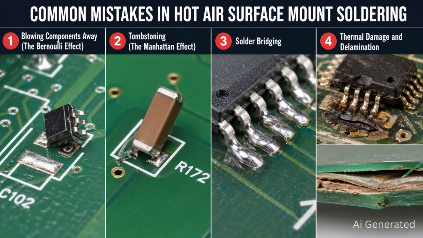
1Blowing Components Away (The Bernoulli Effect)
The most common error with 0402 or 0201 passives is that the airflow velocity is set too fast. The pressure differential is created as the high-speed air flows over a small part — like a wing of an airplane. This can actually make your resistors projectiles! If you are using a small part, then your airflow should be the lowest stable setting (10–20%).
2Tombstoning (The Manhattan Effect)
Tombstoning is when a two-terminal device is standing as tall as a monument. This has to do with an imbalance of torque during the “Silver Flash”. If one side of the paste melts a little earlier than the other, that side will be pulled down, and the other side will be pulled up by the surface tension.
Physics Behind Tombstoning
When the surface tension torque (Eb) is greater than the weight-gravity torque of the part, the part turns over. Equal paste volumes on both pads — delivered by a precision stencil — equalize the torque balance and prevent lift-off.
3Solder Bridging
Bridging is usually due to too much paste. When applying solder paste using a syringe, it's difficult to avoid variable volume. Once reflowed, it expands and spreads on top of the soldermask, producing shorts on fine pitch pins. A laser-cut stencil with controlled aperture geometry eliminates this variable entirely.
4Thermal Damage and Delamination
If any part of the PCB is heated excessively and for an extended period, the moisture might turn to steam and cause “popcorning” — a blistering effect on the FR4 substrate. Likewise, if not adequately protected, nearby plastic connectors can melt. Use a proper preheat soak and Kapton tape masking to avoid these failures.
Essential Tools for Professional Hot Air SMD Work
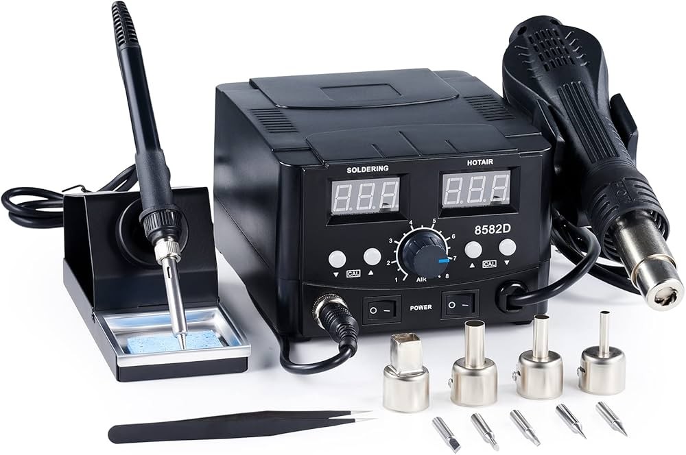
It is necessary to use a particular kit of tools for high-density environments to move from “hacking it” and go on to professional rework.
The Surface Mount Rework Station
Find a station that has closed-loop sensors. This will allow the temperature read on the LED to be the actual temperature of the heating element. The high-end models also have a ‘cool down’ cycle that will keep blowing air until the element temperatures reach below 100°C, which will help to prolong tool life.
The “Secret” Tool: The High-Precision SMT Stencil
The precision SMT stencil is more important for consistency. Most hobbyists concentrate on the heat gun. The 304 HTA stainless steel laser-cut stencil ensures that the same amount of solder is used on each pad. This will prevent bridging and allow the self-alignment action of the solder.
Consumables: Flux and Alloys
Tacky Flux: Tacky flux is a high viscosity, gel-type flux. It has a paste-like consistency that makes it have a great tack adhesion to keep SMD components in place on the pads until reflow starts.
Solder Paste — Sn63/Pb37 (Lead) or SAC305 (Lead-free): For prototype and hobbyist work where RoHS compliance is not required, Sn63/Pb37 is often the easier choice: its 183°C eutectic melting point gives a wider, more forgiving process window with a hot air gun, the joints come out bright and shiny for easier visual inspection, and the molten paste self-aligns components more readily. SAC305 melts higher (217°C–221°C) and demands tighter temperature control, but it is what you must use for any production board intended for the EU market or any customer with RoHS requirements.
Step-by-Step Guide to SMD Soldering With Hot Air
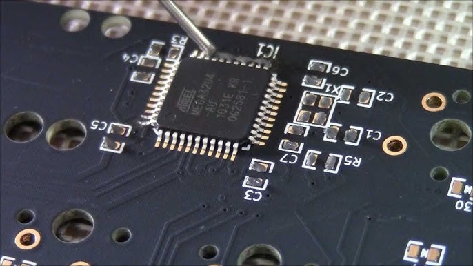
Follow the strictest procedure to maintain metallurgical integrity in your electronic assemblies.
Apply Solder Paste
Place the PCB and position the JLCPCB stencil. Spread solder paste using a squeegee across the apertures to form uniform “bricks” of paste. A quality stencil ensures clean paste release without leaving residual dross in the apertures.
Place the Component
Use anti-static tweezers to place components. Precise placement is not critical — as long as the component is within half the pad width of its target position, the surface tension of liquid solder will self-align the part during reflow.
Preheat the Board
Hold the hot air nozzle 3–5 cm from the board and move in circles to heat the area uniformly. This soak period (60–120 seconds) activates flux, cleans oxides, and allows large and small components to reach thermal equilibrium before reflow begins.
Reflow With Circular Airflow
Move the nozzle closer (1–2 cm) and watch for the “Silver Flash” — the transformation from dull grey paste to shiny molten silver. Once this happens, the component will float into its final self-aligned position.
Cool Naturally and Inspect
Do not blow on the board or move it for at least 30 seconds after reflow. Moving the board while solder is still in the plastic phase creates mechanically stressed “shook-up joints” that will fail intermittently.
Why Stencil Precision Is Vital for Hot Air Reflow Soldering
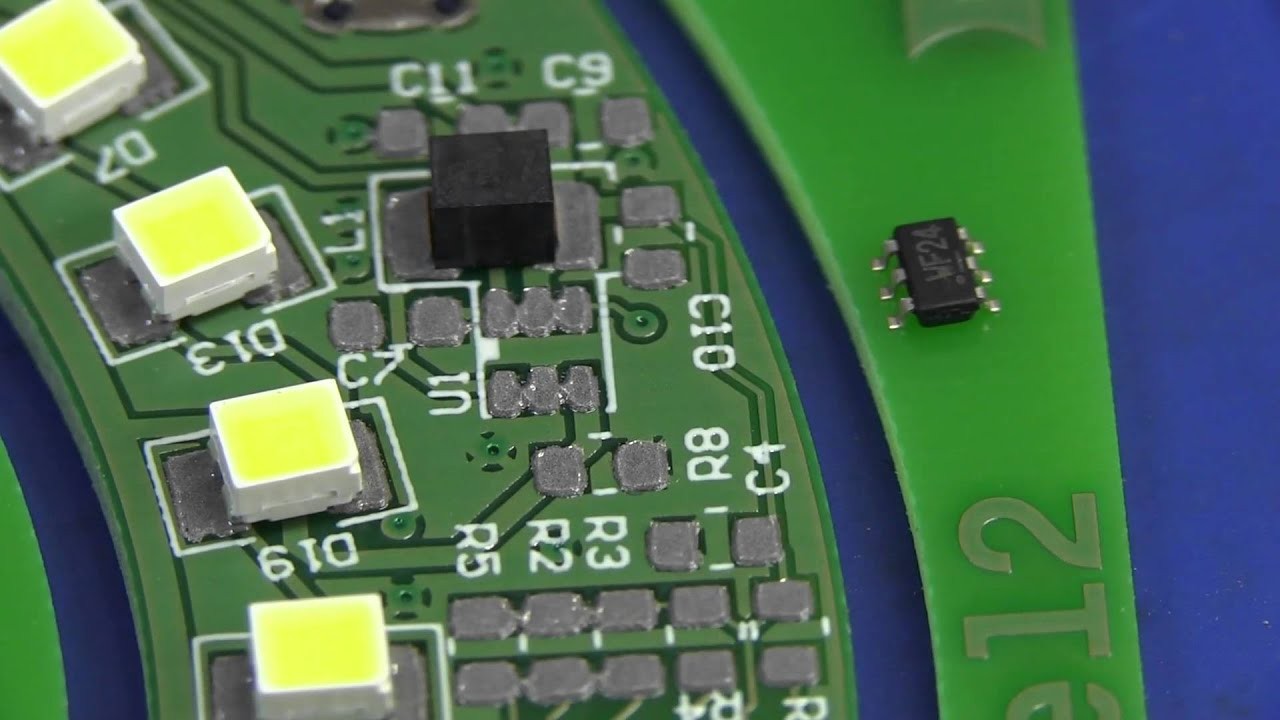
Hot air reflow soldering is a game of tension. If the amount of solder paste is not uniform, the component will experience an unbalanced force during reflow, causing the part to skew or bridge adjacent pads.
The JLCPCB Advantage
JLCPCB stencils address these physics-related predicaments at their source with three key capabilities:
- ±0.003mm Precision: Required for 0.4mm pitch QFNs. It keeps the paste “brick” in place and prevents it from spreading to an adjacent brick during printing.
- 304 HTA Stainless Steel: Grade 304 austenitic stainless steel cold-rolled to full-hard temper, then tension-annealed to relieve internal stress while preserving hardness. The result is an extremely flat foil that resists warpage during laser cutting and holds aperture geometry stable across thousands of print and cleaning cycles — the paste bricks you printed on board #1 are still the same shape on board #1000.
- Electropolishing and Nano-coating: Eliminates burrs on the aperture walls, ensuring full paste release even for the smallest 0201 footprints.
Starting at just $3, these stencils make professional-grade hot air SMD results accessible for every prototype, with a turnaround time as fast as 12 hours.
Optimal Parameters for SMD Soldering With Hot Air
To achieve success in hot air SMD soldering, match your station settings to the solder alloy and component density.
| Alloy Type | Recommended Air Temp | Nozzle Distance | Airflow Logic |
|---|---|---|---|
| Sn63/Pb37 (Leaded) | 260°C – 280°C | 1.5 cm | Low (10–20%) for Passives |
| SAC305 (Lead-Free) | 300°C – 330°C | 1.5 cm | Med (30–50%) for ICs/BGA |
The stencil thickness — standard 0.1mm or 0.12mm — is optimized for these temperature profiles to achieve the best volume-to-surface-area ratio for a clean reflow. Free stencil thickness recommendations are available at JLCPCB.
Choose from Framed/Frameless, Electropolishing, Nano-coating, Step-Stencils, SMD Glue Stencil and more. Starting at $3. No MOQ. 12-Hour production.
Get $11 Coupon Now >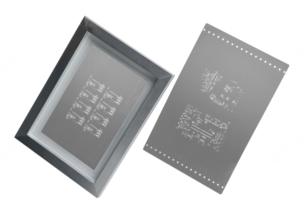
FAQ about Hot Air Surface Mount Soldering
Q: How can I shield plastic connectors adjacent to the component I'm repairing?
Use Kapton (polyimide) tape applied directly to the surface of the component being protected. Aluminum foil placed between the heat source and the connector also reflects radiant heat away. Use both for maximum protection during rework near sensitive plastic housings.
Q: Why does my solder joint look grainy?
A grainy appearance indicates a Cold Solder Joint. This is usually caused by insufficient heat retention above the liquidus temperature or by jolting the board while the solder is still in the plastic phase. Try extending the reflow dwell time or recalibrating your station temperature.
Q: When do I need to use a preheater?
Use a bottom-side preheater when reworking 4-layer or 6-layer boards with large copper ground planes. These act as heat sinks, draining heat from your gun faster than it can be applied. Setting the preheater to 150°C stops the board from warping and allows your hot air gun to bring the target area to liquidus more quickly and uniformly.
Conclusion: Mastering Hot Air Surface Mount Soldering
Hot air surface mount soldering is no longer an advanced skill reserved for repair shops and professional EMS facilities. With a calibrated rework station, the right thermal discipline, and a precision stencil, any engineer or hobbyist can produce joints that match industrial reflow quality.
The critical insight is this: success is 90% preparation. A JLCPCB precision stencil eliminates paste inconsistency — the single most common root cause of SMD failures. Pair it with the temperature profiles and airflow settings outlined above, and the physics of surface tension will handle the rest.
Keep Learning
How to Solder SMD LEDs: A Step-by-Step Guide for Iron, Hot Air, and Reflow
Key Takeaways Confirm polarity and orientation first: Identify the anode and cathode before applying any heat, because a reversed SMD LED will not light and correcting it costs another thermal cycle. Match the method to the job: A fine-tip iron suits one or a few LEDs, hot air is best for rework and single-part replacement, and solder paste with reflow is fastest for complete boards. Keep solder and heat minimal: A small, fully wetted fillet and short dwell times protect the LED die, phosphor, and enc......
How to Solder a Potentiometer (PCB, Panel & Guitar Pots)
Key Takeaways Identify the wiper terminal: In most potentiometers, the middle pin is the wiper. Always verify with a multimeter before soldering. Pre-tin surfaces: Tin both the terminals and wires before joining to ensure strong, clean solder joints. Control heat carefully: Use a temperature-controlled iron and keep contact time short (below 260°C for a few seconds) to avoid damaging the internal resistive track. Test after soldering: Always check continuity and sweep the shaft while measuring output ......
How to Solder QFN Components: A Step-by-Step Guide
Key Takeaways A solder paste stencil is the most reliable way to achieve consistent QFN solder joints. Always use a window-pane paste pattern on the center thermal pad instead of one large paste deposit. Control solder paste volume to prevent floating, bridging, and excessive voiding. Reflow needs a proper soak-then-reflow-then-cool profile Hand soldering is practical only for certain QFN packages and usually cannot solder the center thermal pad effectively. Because QFN solder joints are hidden beneat......
How to Solder Pin Headers: A Step-by-Step Guide
Key Takeaways Breadboard or jig: Use a breadboard or jig to hold the header pin square while you work. Tack one pin first: Check alignment before soldering the rest. Keep heat brief: So the plastic housing doesn't melt. Cut breakaway strips: Score the plastic between pins, not by forcing a cut mid-pin. SMD headers: Soldered with paste and reflow rather than through-hole technique. Desolder a pin: Add fresh solder plus wick or a pump, or use hot air. Introduction You solder a header pin, look at it, an......
Hot Air Surface Mount Soldering: A Step-by-Step Guide
Key Takeaways Heat Control Is Everything: Hot air SMD soldering delivers uniform heat across all pads simultaneously, eliminating the lifted pads and cold joints common with iron-based soldering of fine-pitch components. Airflow Kills Small Parts: Set airflow to just 10–20% for 0402/0201 passives to avoid the Bernoulli Effect that turns tiny resistors into projectiles. Stencil Precision Prevents Tombstoning: A precision-cut SMT stencil deposits equal paste volume on both pads, balancing surface tensio......
Solder Bridging: Preventing a Common PCB Soldering Defect
Modern electronics demand compact PCB layouts with dense pad spacing and miniature components. Engineers deploy 0201 packages, fine pitch QFN devices, and large BGA arrays across SMT assembly lines. These layout conditions increase complexity during reflow soldering and raise the probability of PCB soldering defects. Solder bridging appears frequently within high-density boards that contain narrow pad spacing and large solder paste deposits. A solder bridge forms an unintended conductive path between ......