How to Solder a Potentiometer (PCB, Panel & Guitar Pots)
15 min
- Quick Answer: How to Solder a Potentiometer
- Know Your Potentiometer: Terminals and Types
- Tools and Materials
- How to Solder a PCB-Mount Potentiometer or Trimpot
- How to Solder Wires to a Panel-Mount Pot (Solder Lugs)
- Soldering Guitar Pots (Volume, Tone, and Push-Pull)
- Test the Potentiometer After Soldering
- Common Potentiometer Soldering Problems and Fixes
- FAQ about Soldering a Potentiometer
- Conclusion: Soldering a Potentiometer Cleanly
Key Takeaways
Identify the wiper terminal: In most potentiometers, the middle pin is the wiper. Always verify with a multimeter before soldering.
Pre-tin surfaces: Tin both the terminals and wires before joining to ensure strong, clean solder joints.
Control heat carefully: Use a temperature-controlled iron and keep contact time short (below 260°C for a few seconds) to avoid damaging the internal resistive track.
Test after soldering: Always check continuity and sweep the shaft while measuring output resistance to confirm proper operation.
Potentiometers are one of the most necessary components for electronics featuring adjustable knobs or rotary switches to control volume/tone, brightness, and calibration, among others. They are also popular components for guitar and pedal builds, giving users fine control for adjusting multiple parameters that directly affect the output quality. Essentially, potentiometers feature a wiper terminal connected to a mechanical brush that slides internally within a resistive track, effectively varying the output.
Knowing how to solder a potentiometer effectively requires the right tools and the basic familiarity with the different pot terminals and types. Very often, there are two things that beginners often get wrong in potentiometer soldering: identifying the wiper terminal and overheating the component, especially when grounding to a guitar pot’s metal case.
This article aims to provide users with a guide on how to effectively solder PCB pots, panel pots with lugs, and guitar/audio pots. Soldering push pull pots are also discussed in this guide as part of the section explaining how to solder guitar pots.
Quick Answer: How to Solder a Potentiometer
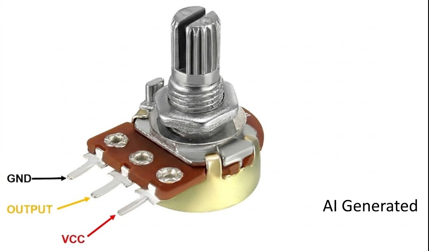
To solder a potentiometer, one must first identify the three terminals correctly. In most pots with three potentiometer terminals, the wiper is usually assigned to the middle terminal. Once the terminals have been determined, tin each terminal and wire, then quickly solder the terminals using a temperature-controlled iron within the manufacturer's recommended temperature (typically below 260°C) for a few seconds to prevent internal track overheating.
Terminal designation for potentiometer soldering
Know Your Potentiometer: Terminals and Types
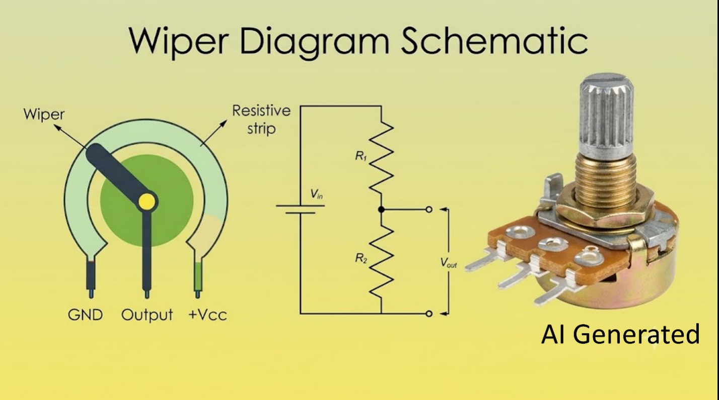
Before you can solder guitar pots or any potentiometers, it is important to understand how common potentiometers work, including their types and terminal specifications. Most potentiometers designate the middle pin as the wiper, commonly considered the varying output. The component essentially works as a voltage divider, where the wiper varies the resistance ratio between itself and each of the outer pins.
The two outer pins connect to the ends of the resistive track. At any point in time, the resistance between the two outer pins is constant. Rotary pots commonly label the ends as CW/CCW, whereas slide pots name the outer terminals as top/bottom, respectively.
The common convention for most potentiometers designates the left pin as the ground, the right pin as the input/signal, and the middle pin as the wiper. With such a convention, the default view is the front with the pins facing down and turning the rotary switch clockwise increases the output. However, although such convention is common for many types of pots, pinouts may vary by maker, so it is essential to verify using a multimeter before attempting solder lug potentiometers, trimpots, or sliders.
Wiper diagram schematic for potentiometers
Besides the terminals, it is also important to verify the labels in the potentiometer before engaging in potentiometer soldering. The two most important things that you must know from the labels are the resistance value and the taper. The resistance value describes the maximum resistance of the whole track while the taper dictates how this resistance value can change as you turn the knob. A linear taper varies the resistance linearly while an audio/log taper changes the resistance logarithmically.
For most applications, the common types of potentiometers that you are likely to encounter are as follows: PCB through-hole pots, SMD trimpots, panel-mount pots with solder lugs and guitar/audio pots. Being able to differentiate these common types, including the relevant labels and terminals, is the first step in learning properly how to solder a potentiometer.
Tools and Materials
Aside from knowing the terminals and types of potentiometers, having the right tools and materials is just as important to ensure successful potentiometer soldering. The most important tool that you must have is a temperature-controlled iron with a fine tip. A temperature-controlled iron gives you the freedom to adjust the temperature based on the terminal specifications of the manufacturer. For instance, some rotary potentiometers such as the PDB18 Series, manufactured by Bourns, can only tolerate a maximum of 260°C for 3 seconds, which is way below the average fixed temperature of non-adjustable soldering irons.
In some cases, a higher-wattage iron or a larger heat-storing tip must be used to properly solder guitar pots, featuring case-back grounding. Choosing the right soldering iron tip shape maximizes the heat transfer without damaging the wiper component of the guitar pot. For this reason, chisel tips, such as Weller's ETC tip from the ETSET-5, are more suitable for establishing a heat-mass point behind case-back grounding.
Alongside the temperature-controlled soldering iron with the proper tip, a variety of other materials are also necessary. Flux-cored solder and extra flux ensure stable bonding of the solder to the metal surface, while a multimeter can be used to verify the pinout beforehand and test the connection after soldering.
To make potentiometer soldering easier, you can also use helping hands or a soldering vise to physically hold the circuit board and the pot. A couple of wires and strippers can also be used especially when soldering push pull pots or lug potentiometers. To avoid melting the carbon track within the potentiometer, you can also use an optional heat-sink clip for very heat-sensitive pots.
How to Solder a PCB-Mount Potentiometer or Trimpot
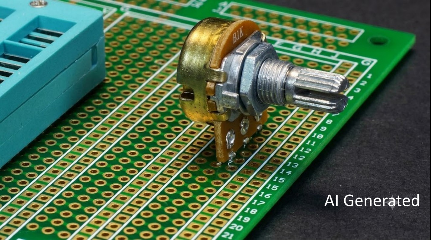
In order to solder PCB-mounted potentiometers or trimpots, you must first seat the component all the way down until the flat surface of the potentiometer makes an even contact with the PCB. Once the component is securely seated, you can proceed to solder the pot's mounting tabs, if they exist, to carry the mechanical load so the electrical pins don't.
For best results, it is recommended to solder the three pins one at a time with brief heat, following the pot manufacturer's temperature and application time tolerances. When soldering small potentiometers, be extra careful not to bridge adjacent pins. If necessary, apply flux if the joint doesn't wet or flow smoothly over the pad.
When soldering SMD trimpots, the process changes slightly. It is recommended to tin one pad first with a tiny amount of solder to serve as the reference for aligning the other terminals. Once the alignment has been fixed, you can then proceed to solder the rest of the pads. As a cautionary measure, inspect for bridges after soldering the SMD trimpot to avoid unintended shorts.
As an alternative, if you are working with an SMD trimpot and various other SMD components in your circuit board, you might want to consider PCB reflow soldering using a hot plate and stencil. Combining a hot plate with an SMT stencil with the appropriate thickness ensures proper SMD trimpot soldering alongside other SMD components without industrial equipment.
PCB-mount potentiometer in a prototype board
How to Solder Wires to a Panel-Mount Pot (Solder Lugs)
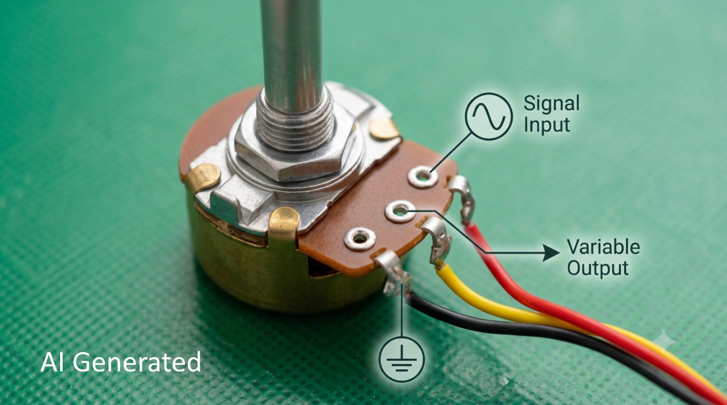
For panel-mount potentiometers that rely on a threaded bushing to fix the potentiometer in place, solder lugs are found instead of the traditional three terminals. The solder lugs are hooked to small wires, following the usual convention of the terminals described earlier in this guide. Learning how to wire a potentiometer with lugs depends on knowing the appropriate lug designations, specified in the potentiometer's datasheet.
To effectively solder lug potentiometers, you must first separately tin both the lug and the stripped wire end. Pre-tinning the stripped wire end protects it from oxidation and ensures instant bonding. After tinning both the lugs and the stripped wires, proceed to hook the respective wires through the guitar pot lugs to establish mechanical grip before soldering.
After going through the previous steps, heat the lug and wire together, deliberately feeding solder to form a shiny fillet that marks a good connection. To prevent damage to the internal carbon track, be sure to keep the iron on only for a few seconds. Once the resistive strip has been damaged due to overheating, a potentiometer can be rendered useless.
For certain applications, you may want to short the unused outer terminal to the wiper. Doing so ensures that in the event that the wiper ever loses contact, the circuit won't fully go open.
Lug potentiometer wiring configuration
Soldering Guitar Pots (Volume, Tone, and Push-Pull)
Knowing how to solder a potentiometer made for guitars requires a slightly different skillset than general potentiometer soldering. For one, guitar pots feature a metal case back, intended to serve as a large heat sink and a common grounding/star-ground point. To make an effective solder connection with the metal case back, lightly scuff the metal surface and tin both the scuffed spot and the ground wire before joining them.
Once the scuffed spot and the wire have been pre-tinned, you can proceed to use a higher-wattage iron or a big soldering tip that can store heat, and complete the joint in a few seconds. The goal is to heat the spot fast before the whole case warms up to prevent overheating of the internals. The quick application is important as prolonged contact can cause heat to reach the wiper, bearing, and carbon track, which can change the pot's turning feel or permanently damage the element.
Assuming the previous steps were done correctly, you will have a good solder joint connecting the ground wire to pot back. You can also apply the previous steps when soldering volume pots or tone pots with a metal ground back case. When building effect pedal PCBs, knowing especially how to solder guitar pots for dynamic volume and tone control is necessary.
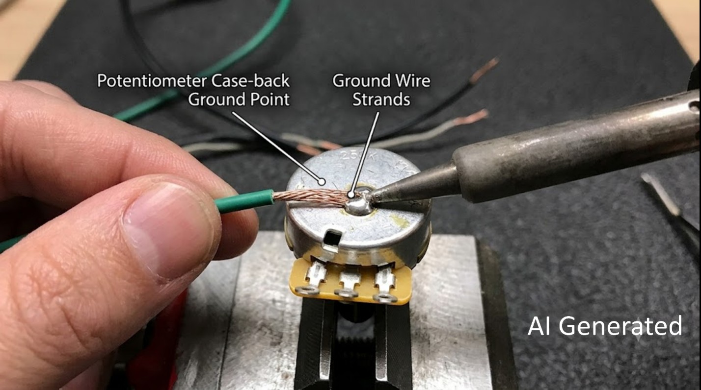
Guitar pot case-back grounding
A special type of potentiometer, which also commonly exists in guitars and other audio amplifiers, is the push-pull potentiometer. Push-pull pots add switch lugs underneath and usually come as audio taper pots with resistance values of 250K/500K for guitar applications. Soldering push pull pots follow a simple guideline. Wire them like any lug pots, but keep heat away from the switch mechanism to prevent irreversible internal damage.
Test the Potentiometer After Soldering
After soldering, it is good practice to test the potentiometer and the solder joints thoroughly. To get started, gently wiggle each joint and the potentiometer, making sure that nothing moves. If there are loose connections, reflow must be done.
Before supplying power to the circuit, check ground continuity and sweep the shaft while measuring the output resistance. The resistance value should change smoothly with no abrupt jumps to an open-circuit condition.
When testing audio circuits, listen for crackles as they might point to cold joints or contamination. Contrary to firsthand assumptions, audio crackles do not always mean the potentiometer is bad.
Common Potentiometer Soldering Problems and Fixes
| Problem | Fix |
|---|---|
| The pot feels stiff or scratchy after grounding to the case. | The case was likely overheated, causing the pot to feel stiff or scratchy. Let the pot cool sufficiently. If the track is damaged, replace it, and work faster with a properly-sized tip next time. |
| The control is scratchy, causing loud statics or crackling when in use. | The wiper is either contaminated or a cold joint is made. Clean the pot with a contact cleaner or attempt to reflow the joint. |
| The control works backwards. | This issue happens when the two outer terminals are swapped. Simply swap the connections of pins 1 and 3. |
| The output value floats or reads dead. | A floating or dead value usually happens when either the wiper or ground terminal isn't connected properly. Check the continuity on all three terminals and perform the appropriate soldering. |
| The housing melted or the shaft wobbles. | When the housing melts or the shaft starts to wobble, it might signal overheating through the terminals. Replace the potentiometer and shorten the iron contact time, while following the temperature limits specified by the manufacturer. |
| The solder cannot make a joint to the case-back ground. | Not enough heat is being transferred for the case and solder to bond. Use a bigger and hotter tip, making sure to tin the surface and the wire before joining. |
FAQ about Soldering a Potentiometer
Q: Where should you put the heat sink when trying to solder guitar pots?
When trying to solder guitar pots or any other potentiometers with a metal ground back, the heat sink should be attached on the threaded part or the shaft to prevent overheating of the internal components. A clip may be used alongside guitar pots to act as a heat sink. This clip will absorb heat instead, preventing irreversible damage to the carbon track.
Q: Can you solder wires to the holes of straight-leg pots?
Technically, you can solder wires to the holes of straight-leg pots, but it is not usually recommended. While soldering wires to these holes could establish a connection just fine, these are made for mechanical stability. The pins themselves offer better electrical contact for making stable electrical joints. If you must solder wires to the terminals, consider getting a lug potentiometer instead.
Q: Do stranded wires work better with potentiometers?
For lug potentiometers, stranded wires, compared to solid wires, offer more flexibility and durability. While some applications might benefit more from solid wires, thin solid wires are prone to breaking when subjected to too much bending. If you must use solid wires, it is recommended to pre-tin both the surface and the exposed wire before establishing a solder joint to ensure durability.
Q: How do you detach all terminals of the potentiometer at once?
To conveniently detach all three terminals of the potentiometer at once, you can use a good solder sucker. Alternatively, you can fill the solder pads with excess solder and use a solder wick to wipe off the heated solder. Depending on how big the solder blob is, you may need to use multiple strips of the solder wick to completely detach all three terminals of the pot.
Q: Is it worth the trouble replacing guitar pots?
Whether it is worth replacing guitar pots depends largely on preference and skill. By following the things taught in this guide, you'll have the fundamentals that you must know to solder most types of potentiometers that you might encounter for guitars and audio applications. Most guitars come with default pots, but replacing them with a higher quality potentiometer can certainly improve durability and output, as long as the components are compatible.
Q: How can you verify if the potentiometer has a linear taper using a multimeter?
To verify the taper type of your potentiometer using a multimeter, you must set up and connect the multimeter probes properly. First, verify the total resistance of the component either by looking at the part label or measuring the resistance using the multimeter by hooking the probes to the outer terminals. Next, adjust the knob incrementally, and verify whether the resistance increases or decreases linearly.
Q: Can you replace trimpots with regular potentiometers, or vice versa?
You can replace trimpots with regular potentiometers, specifically those with linear tapers. As long as the trimpot you are trying to replace has the same resistance rating as the linear taper potentiometer you plan to use, it should work fine. Be sure to review the process elaborated in the section explaining how to solder a trimmer pot as it can be challenging, especially when using it as a substitute for a regular potentiometer.
Q: Why is scuffing necessary for metal ground pots?
For potentiometers featuring a metal ground back case, common for guitars and audio amplifiers, scuffing is a necessary process to establish reliable solder joints. Scuffing is a mechanical process which involves intentionally scratching the metal ground surface, typically using sandpaper. Scuffing removes the chemical barrier which usually prevents the solder from chemically bonding to the metal. Furthermore, it creates microscopic grooves on the metal surface, allowing the liquid solder to easily anchor to the casing when applied.
Conclusion: Soldering a Potentiometer Cleanly
To create clean solder joints for potentiometers, you must follow the guidelines elaborated in this guide. By correctly identifying the wiper terminal, pre-tinning the surfaces, soldering quickly, and respecting the heat limit, you will be able to establish reliable solder joints.
Knowing how to solder a potentiometer, however, is only half the job. You must, as much as you can, perform continuity and sweep tests before powering the circuit on. By applying these potentiometer soldering tips and performing the post-tests thoroughly, soldering all kinds of pots becomes less daunting.
Keep Learning
How to Solder SMD LEDs: A Step-by-Step Guide for Iron, Hot Air, and Reflow
Key Takeaways Confirm polarity and orientation first: Identify the anode and cathode before applying any heat, because a reversed SMD LED will not light and correcting it costs another thermal cycle. Match the method to the job: A fine-tip iron suits one or a few LEDs, hot air is best for rework and single-part replacement, and solder paste with reflow is fastest for complete boards. Keep solder and heat minimal: A small, fully wetted fillet and short dwell times protect the LED die, phosphor, and enc......
How to Solder a Potentiometer (PCB, Panel & Guitar Pots)
Key Takeaways Identify the wiper terminal: In most potentiometers, the middle pin is the wiper. Always verify with a multimeter before soldering. Pre-tin surfaces: Tin both the terminals and wires before joining to ensure strong, clean solder joints. Control heat carefully: Use a temperature-controlled iron and keep contact time short (below 260°C for a few seconds) to avoid damaging the internal resistive track. Test after soldering: Always check continuity and sweep the shaft while measuring output ......
How to Solder QFN Components: A Step-by-Step Guide
Key Takeaways A solder paste stencil is the most reliable way to achieve consistent QFN solder joints. Always use a window-pane paste pattern on the center thermal pad instead of one large paste deposit. Control solder paste volume to prevent floating, bridging, and excessive voiding. Reflow needs a proper soak-then-reflow-then-cool profile Hand soldering is practical only for certain QFN packages and usually cannot solder the center thermal pad effectively. Because QFN solder joints are hidden beneat......
How to Solder Pin Headers: A Step-by-Step Guide
Key Takeaways Breadboard or jig: Use a breadboard or jig to hold the header pin square while you work. Tack one pin first: Check alignment before soldering the rest. Keep heat brief: So the plastic housing doesn't melt. Cut breakaway strips: Score the plastic between pins, not by forcing a cut mid-pin. SMD headers: Soldered with paste and reflow rather than through-hole technique. Desolder a pin: Add fresh solder plus wick or a pump, or use hot air. Introduction You solder a header pin, look at it, an......
Hot Air Surface Mount Soldering: A Step-by-Step Guide
Key Takeaways Heat Control Is Everything: Hot air SMD soldering delivers uniform heat across all pads simultaneously, eliminating the lifted pads and cold joints common with iron-based soldering of fine-pitch components. Airflow Kills Small Parts: Set airflow to just 10–20% for 0402/0201 passives to avoid the Bernoulli Effect that turns tiny resistors into projectiles. Stencil Precision Prevents Tombstoning: A precision-cut SMT stencil deposits equal paste volume on both pads, balancing surface tensio......
Solder Bridging: Preventing a Common PCB Soldering Defect
Modern electronics demand compact PCB layouts with dense pad spacing and miniature components. Engineers deploy 0201 packages, fine pitch QFN devices, and large BGA arrays across SMT assembly lines. These layout conditions increase complexity during reflow soldering and raise the probability of PCB soldering defects. Solder bridging appears frequently within high-density boards that contain narrow pad spacing and large solder paste deposits. A solder bridge forms an unintended conductive path between ......