Thin Film vs. Thick Film Resistors: Key Differences, Advantages & Applications
16 min
- Thick Film vs Thin Film Resistors at a Glance
- Construction Differences: Thin Film vs. Thick Film Resistors
- Performance Comparison: Thin Film vs. Thick Film Resistors
- Cost Comparison: Thin Film vs. Thick Film Resistors
- Application Selection: Thick Film vs Thin Film Resistors
- When to Use Thick Film Resistors
- When to Use Thin Film Resistors
- Sourcing SMD Resistors for PCB Assembly
- Common Resistors Selection Mistakes
- SMD Resistor Types Explained
- FAQs about SMD Resistors
Key Takeaways
- Default to thick film resistors for most designs. They are cost-effective, robust, and ideal for pull-ups, LED current-limiting, digital circuits, and surge-prone applications.
- Choose thin-film resistors whenever a resistor defines an analog quantity, such as a voltage divider, reference network, gain-setting circuit, or current-sensing signal chain. Their tight tolerance and low TCR help maintain measurement accuracy over temperature and time.
Most PCB designs use thick film or thin film resistors, but choosing the wrong one can lead to unnecessary cost—or worse, measurement errors and temperature drift.
This guide explains the key differences and shows when to use each with practical examples and real engineering data.
Thick Film vs Thin Film Resistors at a Glance
Thick-film resistors are screen-printed, inexpensive, and robust — the default for roughly 95% of positions.
Thin-film resistors are sputtered and laser-trimmed for precision: tighter tolerances, lower TCR, lower noise, and better long-term stability, typically at 5–10× the cost.
Use thin film only where the resistor sets an analog quantity; use thick film for everything else.
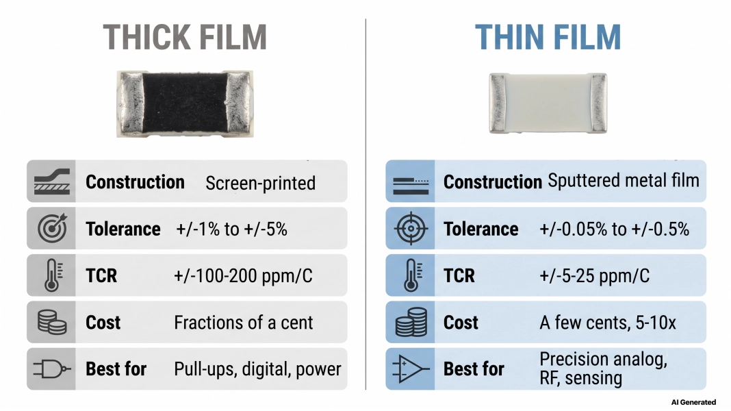
Figure: The differences between thick film and thin film resistors
| Property | Thick film resistors | Thin film resistors |
|---|---|---|
| Long-term drift | Higher (hundreds of ppm) | Very low (tens of ppm) |
| Current (electrical) noise | Higher | Very low |
| Frequency behavior | More parasitic, less ideal at RF | Cleaner, preferred for RF |
| Surge/pulse tolerance | Excellent | Poorer (thin element) |
| Resistive layer | Screen-printed paste, ~10–100 µm | Sputtered metal film, ~0.1 µm |
Construction Differences: Thin Film vs. Thick Film Resistors
Everything downstream from tolerance, TCR, noise, and cost traces back to how the resistive layer is deposited.
Thick Film Resistor Construction— Screen-Printed Paste Fired on Ceramic
A thick film resistor is made by screen-printing a resistive paste (usually a ruthenium-oxide, RuO₂, blend suspended in glass frit) onto an alumina ceramic substrate, then firing it at around 850 °C so it fuses into a durable film roughly 10–100 µm thick.
The value is set coarsely by the paste and geometry, then trimmed with a laser cut into the film. Terminations are printed and plated. It's a fast, cheap, high-volume process. Which is exactly why thick film is the default chip resistor you'll find in JLCPCB's basic parts library and on nearly every board.
Thin Film Resistor Construction— Sputtered Metal Film, Laser-Trimmed
A thin film resistor is made by sputtering a very thin metal-alloy layer, typically nichrome (NiCr) or a tantalum nitride, onto a ceramic or silicon substrate under vacuum. That film is only about 0.1 µm thick, roughly 100–1000× thinner than a thick film layer, and it's photo-etched and laser-trimmed to a tight value.
The homogeneous metal film is what buys you the low TCR, low noise, and tight tolerance. The vacuum deposition and trimming steps are what make it cost more.
Performance Comparison: Thin Film vs. Thick Film Resistors
This is where the decision is actually made. Below are the key properties that separate the two films, with real numbers in each.
Tolerance: ±1–5% vs ±0.05–0.5%
Tolerance is how close the delivered value is to the marked value, at room temperature, on day one. Standard thick film lands at ±1% (E96) to ±5% (E24); you can buy ±0.5% thick film, but it gets expensive fast. Thin film routinely delivers ±0.1%, ±0.05%, or even ±0.02%.
If your circuit's accuracy depends on the ratio or absolute value of a resistor, say a divider or maybe a gain network, then the tolerance is your first filter. If it just needs to be "about 10 kΩ" (a pull-up), tolerance barely matters.
TCR — Temperature Coefficient of Resistance
TCR tells you how much the resistance moves per degree of temperature change, in ppm/°C. Thick film sits at ±100 to ±200 ppm/°C; thin film at ±5 to ±25 ppm/°C, which is an order of magnitude better. And here's the trap: tolerance is a day-one, room-temperature spec. TCR is what wrecks you in the field, because your board runs hot.
Example (the drift that eats your ADC counts): Let's say that you have a resistor divider feeding a 10-bit ADC (range 5V, so 1 LSB is around 4.9 mV). Say the temperature rises from 25 °C to 75 °C, near a regulator or outside a box.
- Thick film at 100 ppm/°C:
100 ppm/°C × 50 °C = 5000 ppm = 0.5% shift.
If the two divider legs do not track, the output error may range from hundreds of µV to a few mV, or on the order of 5 LSBs, without doing anything wrong.
- Thin film at 10 ppm/°C:
10 ppm/°C × 50 °C = 500 ppm = 0.05% is roughly half an LSB.
That 10× difference is the entire reason thin film exists. A worked-through 100 ppm/°C vs 10 ppm/°C comparison is plotted below.
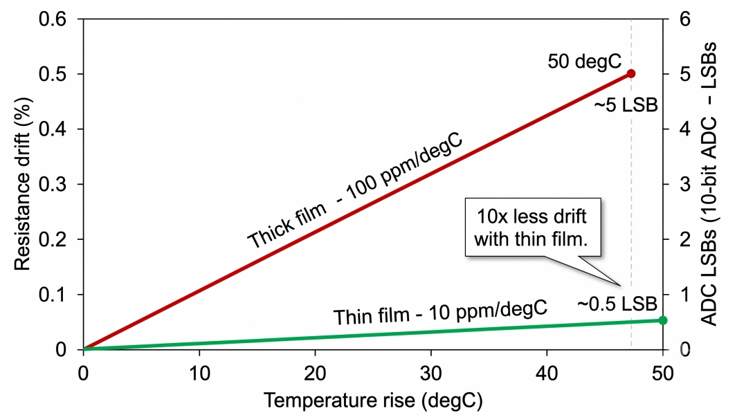
Figure: Resistor TCR drift graph comparing a 100 ppm/°C thick film resistor and a 10 ppm/°C thin film resistor over a 50 °C temperature rise, shown as ADC LSB error
Noise & Long-Term Stability
Two failure modes hide here.
First, current (excess) noise: quantified by the current-noise index in dB (µV per volt applied). Thick film's granular, glass-filled structure generates measurably more excess noise than thin film's homogeneous metal, which matters in low-level analog front-ends and sensor amplifiers.
Second, long-term drift: thick film can shift by hundreds of ppm over years and load-life, while thin film typically holds to tens of ppm. Tolerance covers day one; drift covers the next ten years. A "1% thick film" is not a "precision resistor," it just started life close to value.
Frequency Behavior & Parasitics — Why RF Prefers Thin Film
At RF, a resistor stops being a pure resistor. Thick film's thicker, less-uniform element and printed terminations add more parasitic inductance and capacitance, and its RuO₂ structure is less ideal at GHz.
- Thin film's thin, smooth, homogeneous layer behaves closer to an ideal resistor to higher frequencies, giving a flatter response and better return loss.
- For RF matching, attenuators, and high-speed termination, thin film (or specialty RF thin film) is the standard choice.
Surge, Power & Environmental Robustness — Where Thick Film Wins
Here, the trade-off flips, and honesty matters: thick film wins robustness. Its thicker resistive element absorbs pulse and surge energy far better than thin film's fragile 0.1 µm layer, which can be damaged or shifted by a single overstress event. Thick film also generally handles higher power in the same footprint and tolerates harsh conditions well.
The one classic thick-film weakness is sulfur corrosion: silver in the inner termination can react with airborne sulfur and go open-circuit, which is exactly why anti-sulfur and AEC-Q200 automotive-grade thick films exist. If your position sees ESD, inrush, or hot-swap surges, thick film is usually the safer element. For sizing power correctly regardless of film, see our resistor power rating guide.
Cost Comparison: Thin Film vs. Thick Film Resistors
Follow the money, and the "95% rule" explains itself. A standard thick film chip resistor costs fractions of a cent in reel quantities; an equivalent precision thin film part costs a few cents, 5–10× premium, and more for tight tolerance.
On a board with 80 resistors, defaulting everything to thin film could add a dollar or more per board; the real money is at 1,000+ units.
So the discipline is simple: place thick film everywhere by default, and spend thin film only where an analog spec demands it. Where precision genuinely pays back, less factory calibration, higher yield, fewer field returns, the thin film is cheap insurance.
Application Selection: Thick Film vs Thin Film Resistors
| Application | Recommended film | Tolerance | TCR |
|---|---|---|---|
| Pull-up/pull-down | Thick film | ±5% (±1% fine) | ±200 ppm/°C |
| LED current-set | Thick film | ±5% | ±200 ppm/°C |
| Power-rail feedback divider | Thin film | ±0.1–0.5% | ±25–50 ppm/°C |
| ADC front-end/divider | Thin film | ±0.1% | ±10–25 ppm/°C |
| Voltage reference network | Thin film | ±0.05–0.1% | ≤10 ppm/°C |
| Amplifier gain-setting | Thin film (matched pair) | ±0.1% | ≤25 ppm/°C |
| Current sense (signal chain) | Thin film or metal strip | ±0.1–1% | ≤50 ppm/°C |
| RF matching/termination | Thin film | ±1% | ±25 ppm/°C |
| Automotive/harsh env. | Thick film (AEC-Q200, anti-sulfur) | ±1% | ±100 ppm/°C |
Tolerance & TCR Decoded
Most of the table above is based on two numbers, so be sure to read them correctly. Tolerance is first accuracy at ambient temperature; it does not imply anything about the behavior of the part when your board is hot, or if the part gets old. Drift with temperature is controlled by TCR, and drift with time is controlled by long-term stability.
What's often confused is that a ±1% part is considered "precision" since 1% is tight. However, a ±1% thick film having a TCR of 200 ppm/°C will change its coefficient by another ±1% when the temperature changes by 50 °C. So its actual in-circuit accuracy is worse than what it says on the label.
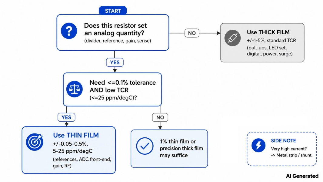
Figure: Decision flowchart for choosing thick film vs thin film SMD resistors based on whether the resistor sets an analog quantity, its tolerance, and TCR requirements
Rule of thumb
5% is fine for pull-ups and current-set; 1% is enough for non-critical dividers and most digital-adjacent analog; and 0.1% with ≤25 ppm/°C is mandatory the moment the resistor sets a reference, gain, or measurement. The EIA-96 3-character marking is itself a precision hint - decode it in our SMD resistor code guide.
When to Use Thick Film Resistors
Reach for thick film when the exact value and its stability don't set a measured quantity:
- Pull-up/pull-down resistors: Logic just needs "high enough"; ±5% is plenty.
- LED current limiting: A few percent of brightness variation is imperceptible.
- Series/damping and general digital: Timing and edges don't care about ppm.
- Gate resistors, bleed/discharge, snubbers: Robustness beats precision.
- Power positions and surge-exposed nodes: Thick film's pulse tolerance is an advantage.
- High-volume cost-sensitive BOMs: The default that keeps unit cost down.
When to Use Thin Film Resistors
Reach for thin film when the resistor sets an analog quantity, and its accuracy or stability is part of the spec:
- Precision voltage dividers: Where the ratio defines a measured voltage or setpoint.
- Voltage-reference and bias networks: TCR directly limits reference accuracy over temperature.
- Amplifier gain-setting resistors: Gain error and gain drift come straight from tolerance and TCR.
- Current-sensing signal chains: Matched, low-TCR resistors keep the measurement honest over temperature.
- Medical, test, and instrumentation: Long-term stability and low noise are non-negotiable.
- RF matching and attenuators: Clean high-frequency behavior.
Sourcing SMD Resistors for PCB Assembly
Choosing the right film is half the job; the other half is getting the exact part placed on your board without a stockout. This is where the JLCPCB Parts Library does the heavy lifting.
Basic vs extended parts: JLCPCB splits its SMD inventory into basic and extended parts. Basic parts are pre-loaded on the assembly machines with no extra setup fee, and standard thick film chip resistors (the common values and tolerances) live here, which is another reason thick film is the sensible default.
Thin film and tight-tolerance/low-TCR precision resistors are mostly extended parts: still stocked and easy to order, but they may carry a small feeder setup fee, and you should confirm live stock before locking your BOM. Planning your precision positions early avoids last-minute substitutions.
How to filter: In the Parts Library, filter chip resistors by resistance, tolerance, TCR, package size, and basic/extended flag, and check the verified in-stock quantity before you commit.
When you're comparing two candidates, the EIA-96 marking on the part is a quick precision tell — a 3-character code generally signals a tight-tolerance (often thin film) part.
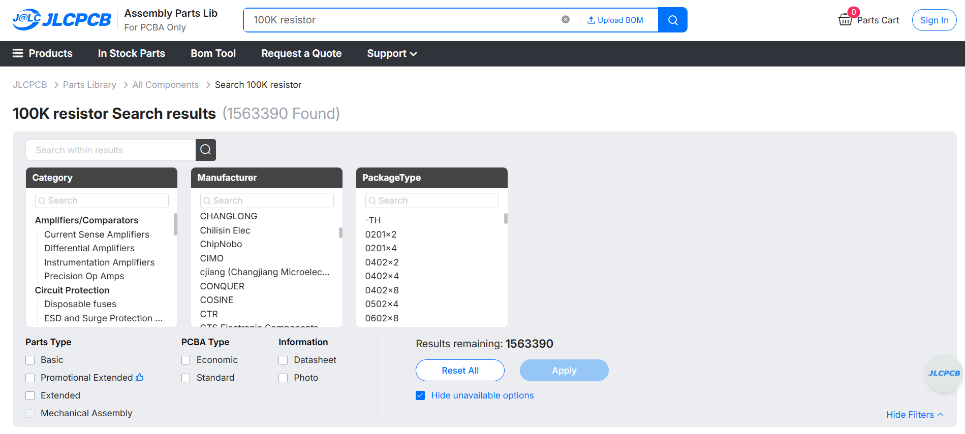
Figure: Search SMD resistors at JLCPCB Parts Library 
Figure: JLCPCB Parts Library filtering SMD resistor types by tolerance, TCR, package
Once your resistors are picked, drop your BOM straight into the JLCPCB quote page to get boards fabricated, parts sourced, and assembly done in one order.
Common Resistors Selection Mistakes
- Using 1% thick film in a reference divider. Tolerance looks fine; TCR and drift blow the accuracy over temperature and time. Use thin film with low TCR.
- Ignoring self-heating in sense positions. A shunt or divider dissipating power heats itself, shifting its own value — a high-TCR part makes this worse.
- Paying for thin film on pull-ups. Precision where it does nothing is just wasted BOM cost. Default those to thick film.
- Ignoring sulfur environments. Standard silver-electrode thick film can go open in sulfur-rich air; specify anti-sulfur or AEC-Q200 parts for automotive and industrial builds.
- Assuming tolerance covers lifetime drift. It doesn't. A tight day-one tolerance says nothing about where the part sits in ten years — check stability, not just tolerance.
SMD Resistor Types Explained
The main SMD resistor types are thick film, thin film, metal strip (shunt), MELF, resistor arrays/networks, zero-ohm jumpers, and surface-mount wirewound.
Thick film and thin film cover the overwhelming majority of designs; the rest are specialty parts for current sensing, high stability, jumpering, or power. The table below is for your quick reference.
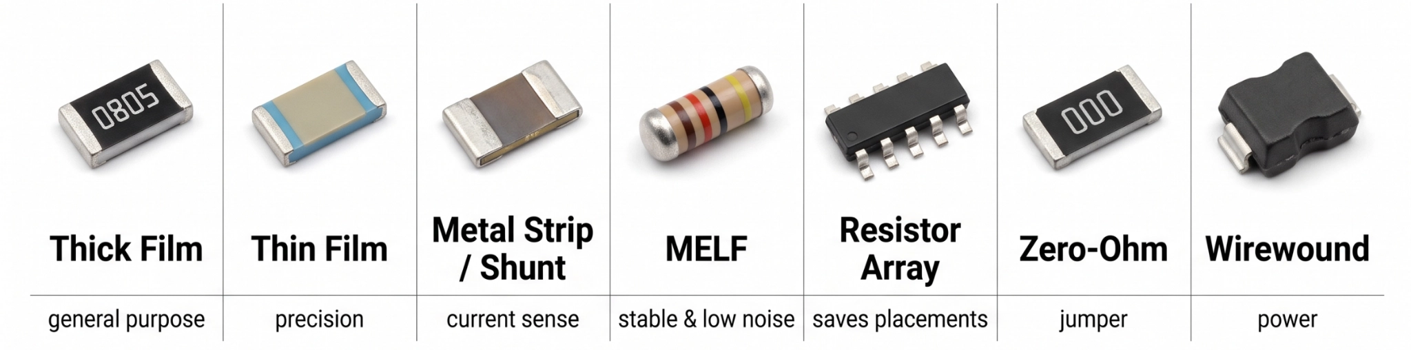
Figure: SMD resistor types chart showing thick film, thin film, metal strip shunt, MELF, resistor array, zero-ohm, and wirewound chip resistors
| SMD resistor type | How it's built | Best for |
|---|---|---|
| Thick film resistor | Resistive paste screen-printed and fired on a ceramic substrate | Pull-ups/downs, digital, LED current-set, general purpose |
| Thin film resistor | Sputtered metal alloy film, laser-trimmed to value | Precision analog: dividers, references, gain-setting, sensing |
| Metal strip/shunt resistor | Solid low-value metal element (milliohms) | Current sensing at high current |
| MELF resistor | Cylindrical body with a thin/metal film on a glass core | Stable, low-noise, pulse-tolerant precision in a leadless barrel |
| Resistor array/network | Multiple matched resistors in one package (isolated or bussed) | Bus terminations, pull-up banks, saving board space, and placements |
| Zero-ohm resistor | A jumper in a resistor footprint | Configurable links, layout jumpers |
| Wirewound resistor (SMD) | Resistance wire wound on a core, molded into a chip body | Higher power, high pulse energy, low-value precision at power |
Thick and thin film cover most boards, but the specialty families earn their place in the right position:
- Metal foil: A bulk metal foil bonded to a substrate; the ultimate in precision, with tolerances to ±0.005% and TCR near 1 ppm/°C for metrology and lab references, at premium cost.
- Metal strip/shunt: A solid low-value metal resistor (as low as sub-milliohm) designed to measure high currents; typically 4-terminal (Kelvin) to reduce lead resistance and has a low TCR to ensure accuracy in the measured current.
- MELF: cylindrical, leadless body with excellent stability, low noise, and good pulse handling; strong precision option in which its round footprint fits.
- Wirewound (SMD): Resistance wire on a core for higher power and high pulse energy, plus low-value precision at power; bulkier and inductive, so not for high frequency.
- Resistor arrays/networks: Several matched resistors in one package (isolated or bussed) that save placements and space in bus terminations and pull-up banks, with good matching between elements.
- Zero-ohm jumpers: A link in a resistor footprint used as a configurable jumper or populate/depopulate option in layout; spec'd by max resistance and current, not value.
Package size interacts with all of these — a shunt and a pull-up may share an 0805 footprint, but nothing else. See the complete guide to SMD resistor package sizes for the footprint side.
FAQs about SMD Resistors
Q: What are the main types of SMD resistors?
The main SMD resistor types are thick film, thin film, metal strip (shunt), MELF, resistor arrays/networks, zero-ohm jumpers, and surface-mount wirewound. Thick film is the general-purpose default, and thin film is the precision choice; the rest are specialty parts for current sensing, high stability, jumpering, or higher power.
Q: What is the difference between thick film and thin film resistors?
Thick film resistors use a screen-printed resistive paste (~10–100 µm) fired on ceramic — cheap and robust, with ±1–5% tolerance and ±100–200 ppm/°C TCR. Thin film resistors use a sputtered, laser-trimmed metal film (~0.1 µm) with far tighter tolerance (±0.05–0.5%), lower TCR (±5–25 ppm/°C), lower noise, and better stability, at 5–10× the cost.
Q: Why are thin-film resistors more expensive?
Thin film requires vacuum sputtering of an ultra-thin metal-alloy film, photo-etching, and precision laser trimming — slower, more capital-intensive steps than screen-printing and firing a thick film paste. You're paying for the tight tolerance, low TCR, low noise, and long-term stability that those extra process steps deliver, typically a 5–10× premium.
Q: When is thick film good enough for analog circuits?
Thick film is fine for analog wherever the resistor doesn't set a precisely measured quantity — series/damping resistors, biasing that a feedback loop corrects, filters where a few percent of corner shift is acceptable, and non-critical dividers. Switch to thin film once tolerance under ±1%, low TCR, or long-term stability directly affects accuracy.
Q: Which type is better for RF circuits?
Thin film is better for RF. Its thin, uniform metal layer has fewer parasitics and behaves closer to an ideal resistor at high frequency, giving flatter response and better return loss for matching networks, attenuators, and high-speed termination. Thick film's thicker, granular element is less ideal above roughly the low-GHz range.
Q: What is a zero-ohm SMD resistor used for?
A zero-ohm SMD resistor is a jumper in a resistor footprint — essentially a near-0 Ω link (spec'd by maximum milliohms and current, not value). Designers use them as configurable jumpers, layout links to cross traces, and populate/depopulate options to reconfigure a board without changing the copper.
Popular Articles
• SMD Resistor Package Sizes: Complete Size Chart, Footprints & How to Choose
• How to Solder SMD Components Like a Pro [2026 Updated]
• SMD Resistor Codes: How to Read 3-Digit, 4-Digit, and EIA-96 Markings
• SMD Capacitor Codes: Identification, Markings, and Polarity
• SMD Capacitor Sizes: Complete Size Chart and Selection Tips for PCB Design and Assembly
Keep Learning
SMD MOSFET Code Guide: How to Identify, Test and Replace a MOSFET
Figure: AO3400A (C20917) in the JLCPCB parts library. The listing gives RDS(on) at 2.5 V gate drive, the number that matters in the replacement example later in this guide. An SMD MOSFET code is the two or three characters printed on top of the package, and on its own it rarely tells you which part you're holding. SMD resistors follow standard marking schemes, such as three- and four-digit codes and EIA-96. MOSFETs don't. The same short code can appear on unrelated parts from different manufacturers, ......
ESP8266 vs ESP32: Which One Should You Use?
Key Takeaways ESP32: Dual-core 240 MHz CPU, Bluetooth Classic and BLE, 520 KB SRAM, and up to 34 GPIOs. ESP8266: Single-core CPU, no Bluetooth, and around 50 KB of free RAM for applications. Lifecycle status: Espressif marks the ESP8266 Not Recommended for New Designs (NRND) and names the ESP32-C2 (ESP8684) as its upgrade, although the ESP8266 remains in production with a longevity commitment. Which ESP32 to use: Choose the ESP32-C2 for simple Wi-Fi or Bluetooth LE firmware, the ESP32-C3 for more memo......
What Is a Thermistor? A Practical Guide to NTC, PTC, Applications, and Circuit Design
Key Takeaways Definition: A thermistor is a thermally sensitive resistor whose resistance changes markedly and predictably with temperature, typically by about 4.4% per °C for a standard 10 kΩ NTC (B25/50 = 3950 K) near 25 °C. NTC vs. PTC: An NTC thermistor's resistance falls as temperature rises, which suits temperature sensing and inrush current limiting; a switching PTC's resistance rises steeply above its switch temperature, which suits circuit protection. Key Specifications: An NTC thermistor is ......
What Is the ESP32-CAM, and How to Wire, Power, and Program It?
Key Takeaways Board, not chip: The ESP32-CAM is an AI-Thinker development board, not an Espressif product. It carries AI-Thinker's ESP32-S module, an OV2640 camera, PSRAM, a microSD slot, and a flash LED. No USB port: The board has no USB connector or USB-to-UART bridge, so you program it via its serial pins using a 3.3 V USB-to-serial adapter, with GPIO0 held low at reset. Few free pins: The camera, PSRAM, and microSD card occupy most GPIOs. With the microSD card unused, GPIO2, GPIO4, GPIO12, GPIO13,......
ESP32 Versions: Which One Should You Use for Your Project?
Key Takeaways Radios decide first: ESP32 versions differ mainly in their radios, CPU cores, and peripherals. Common defaults: The ESP32-C3 suits low-cost Wi-Fi and Bluetooth LE, the ESP32-S3 suits camera, display, voice, and on-device AI. Original ESP32: The chip is still in production and remains the choice for Bluetooth Classic. Versions without Wi-Fi: The ESP32-H2 targets battery-powered Thread and Zigbee devices. Chip, module, or board: Prototype on a development board, then design a module onto y......
SOIC Package: A Complete Guide to Specifications, Types, Uses, and SMT Assembly
As designs transition from legacy through-hole components to high-density Surface Mount Technology (SMT), the Small Outline Integrated Circuit (SOIC) remains the industry standard for operational amplifiers, flash memory, sensors, and microcontrollers. It reflects a well-balanced engineering design, offering a practical compromise between the miniaturisation demanded by modern consumer electronics and the ruggedness required for industrial applications. In this guide, you will learn: SOIC package dime......