
Resistor Power Rating: How to Calculate Wattage for SMD and Through-Hole Resistors
10 min
- What Is Resistor Power Rating?
- How to Calculate Resistor Power Rating (Formulas and Example)
- Quick Resistor Wattage Selection Table
- SMD Resistor Power Rating Chart (0201 to 2512 Packages)
- Through-Hole Resistor Wattage Guide (1/8W to 5W and Above)
- Resistor Derating Curve Explained
- PCB Thermal Design Tips for Maximizing Effective Resistor Power Rating
- What Happens If a Resistor Exceeds Its Power Rating?
- FAQs
- Conclusion
Every electronic circuit generates heat. Resistors, as their name implies, restrict current by converting electrical energy into thermal energy. But how much heat is too much?
Understanding the resistor power rating is critical for any hardware designer. It defines the maximum continuous power (in watts) a component can safely dissipate without degrading.
If you don't know how to calculate resistor wattage accurately, you risk thermal runaway, damaged components, or even a completely burned PCB. Whether you are breadboarding a simple LED circuit or moving to professional PCB Assembly using dense SMT and robust THT components, selecting the correct wattage is foundational.
In this guide, you will learn:
- How to calculate resistor wattage
- SMD resistor power rating chart
- Through-hole wattage guide
- Derating curve explanation
- PCB thermal design tips
What Is Resistor Power Rating?
Resistor power rating is the maximum amount of electrical power a resistor can safely convert into heat without permanent damage. It is measured in watts and depends on resistor size, material, ambient temperature, and PCB thermal conditions.
Selecting the correct wattage ensures your components do not overheat, protecting both the resistor and the surrounding circuitry from performance degradation or catastrophic failure.
How to Calculate Resistor Power Rating (Formulas and Example)
Before selecting a component, you must calculate the exact power it will dissipate. Power dissipation is governed by Joule’s Law and Ohm’s Law. Depending on the known values in your circuit - voltage (V), current (I), or resistance (R) - you can calculate power (P) using one of these three formulas:
-
P=VI (when voltage drop and current are known)
-
P=I^2 R (when current and resistance are known)
-
P=V^2/R (when voltage drop and resistance are known)
Quick Calculation Rule: Calculate power using P=I^2 R or P=V^2/R. Always choose a resistor with at least a 2× higher wattage rating than the calculated dissipation.
Once you calculate the theoretical power dissipation, you must apply this engineering safety margin. For example, if your math shows a resistor will dissipate 0.12W, you should select a 0.25W (1/4W) rated component. This buffer ensures the resistor operates well below its absolute maximum thermal limit, extending its lifespan and protecting surrounding sensitive components from excessive ambient heat. Let's look at a practical scenario.
Practical Example - Selecting Resistor Wattage in a 12V Circuit
Suppose you are designing a control circuit powered by a 12V supply. You need to drop this voltage across a resistor to limit the current to a specific load at 100 mA (0.1 A).
Step 1: Calculate the required resistance
Using Ohm's Law
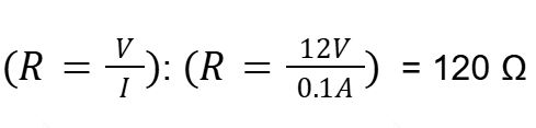
Step 2: Calculate power dissipation
Using the power formula
![]()
Step 3: Apply the safety margin
Applying the 2× safety rule: 1.2 2 = 2.4W. You need a resistor rated for at least 2.5W to 3W.
Decision Making:
- Through-Hole Option: A 3W metal oxide THT resistor is ideal here. Its physical size allows for excellent airflow, and it handles inrush current surges beautifully.
- SMD Option: A standard single SMD resistor will melt under this load. You would need either a specialized high-power 3W SMD resistor or, more commonly, two 2512-package resistors (~1W to 1.5W each) wired in parallel to split the thermal load safely.
Quick Resistor Wattage Selection Table
The table below helps you quickly choose the correct resistor wattage rating based on calculated power dissipation.
|
Calculated Power |
Recommended Rating |
Typical THT Choice |
Typical SMD Choice |
|---|---|---|---|
|
0.025 W |
0.05 W |
1/8 W carbon film |
0201 |
|
0.03 W |
0.062 W |
1/8 W carbon film |
0402 |
|
0.05 W |
0.125 W |
1/8 W carbon film |
0603 |
|
0.12 W |
0.25 W |
1/4 W metal film |
0805 |
|
0.30 W |
0.50 W |
1/2 W metal oxide |
1206 |
|
0.80 W |
2.0 W |
2 W power resistor |
2× 1210 parallel |
|
1.20 W |
3.0 W |
3 W wirewound |
2512 ×2 |
Table: Recommended quick resistor wattage selection table
Design Insight: In high-density SMT boards, distributing heat across multiple parallel resistors often improves long-term reliability compared to relying on a single high-power component.
SMD Resistor Power Rating Chart (0201 to 2512 Packages)
In Surface Mount Technology, a resistor's physical footprint directly dictates its power rating. The larger the ceramic substrate, the more surface area is available to transfer heat into the surrounding air and the PCB copper traces. Engineers often search for an SMD resistor power rating chart to match package size with safe thermal limits.
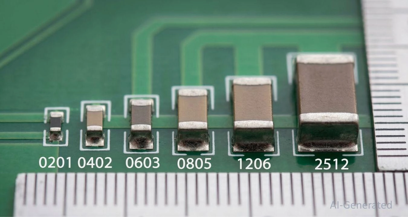
Figure: Size comparison of various surface mount SMD resistors ranging from tiny 0201 packages up to 2512 power packages.
|
SMD Package Size |
Typical Power Rating (Fractions) |
Typical Power Rating (Decimals) |
|---|---|---|
|
0201 |
1/20 W |
0.05 W |
|
0402 |
1/16 W |
0.0625 W |
|
0603 |
1/10 W |
0.10 W |
|
0805 |
1/8 W |
0.125 W |
|
1206 |
1/4 W |
0.25 W |
|
1210 |
1/2 W |
0.50 W |
|
2010 |
3/4 W |
0.75 W |
|
2512 |
1 W |
1.0 W |
Table: SMD Resistor Power Rating Chart
Standard SMD sizes follow predictable wattage limits as shown in the chart above. While tiny 0201 packages are strictly for low-power signal routing, heavier power applications rely on larger 1206 or massive 2512 packages. However, real power capability also depends on PCB copper area and airflow, not only on package size.
When inspecting a densely populated board, confirming these values visually can be challenging. We recommend keeping an SMD resistor code guide handy to decode the marking digits on 0603 sizes and up. When you are ready to move from schematic to layout, you can easily source all these standard packages and specialized high-power variants directly from the JLCPCB Parts library.
Through-Hole Resistor Wattage Guide (1/8W to 5W and Above)
Despite the dominance of surface-mount components, Through-Hole Technology (THT) remains indispensable for power electronics. THT resistors naturally sit slightly above the PCB, allowing 360-degree ambient airflow to carry heat away, unlike SMDs, which dump heat directly into the board. In many high-power designs, through-hole resistors are preferred over SMD resistors due to superior airflow and easier heatsinking.
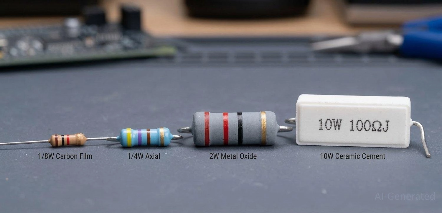
Figure: Different types of through-hole resistors arranged by power rating, including carbon film, metal oxide, and a high-wattage white ceramic cement resistor.
|
THT Resistor Type |
Typical Power Rating Range |
Common Application |
|---|---|---|
|
Carbon Film |
1/8 W – 1/2 W |
General-purpose, prototyping |
|
Metal Film |
1/8 W – 1 W |
Precision circuits, low noise |
|
Metal Oxide |
1 W – 5 W |
Power supplies, medium loads |
|
Wirewound (Ceramic) |
5 W – 50 W+ |
Motor control, audio crossovers |
|
Thick Film (TO-220) |
20 W – 100 W+ |
High-power heatsink mounting |
Table: Through-Hole Resistor Wattage Guide
As detailed above, standard carbon and metal film THT resistors cover lower power ranges, with the ubiquitous breadboard resistor usually being a 1/4W axial component. When pushing beyond 5W for heavy loads, designs shift to ceramic cement resistors (which usually house a wirewound element) or thick-film power resistors in TO-220 casings that bolt directly to aluminum heatsinks.
If you are debating whether to use a bulky wirewound component or a high-power SMD array, reviewing the trade-offs of surface mount vs through-hole technology can help finalize your architecture based on your enclosure's constraints.
Resistor Derating Curve Explained
Why does wattage reduce with Temperature?
A critical error novice engineers make is assuming a 1/4W resistor can dissipate 0.25W in any environment. Power ratings are standardized at a specific ambient temperature - usually 70°C. If the air around the resistor exceeds this threshold, its ability to shed heat drops, requiring a "derating" of its maximum power capacity. Most resistor datasheets specify a full 100% power rating from -55°C up to 70°C ambient, and then linearly derate to zero near 150–155°C.
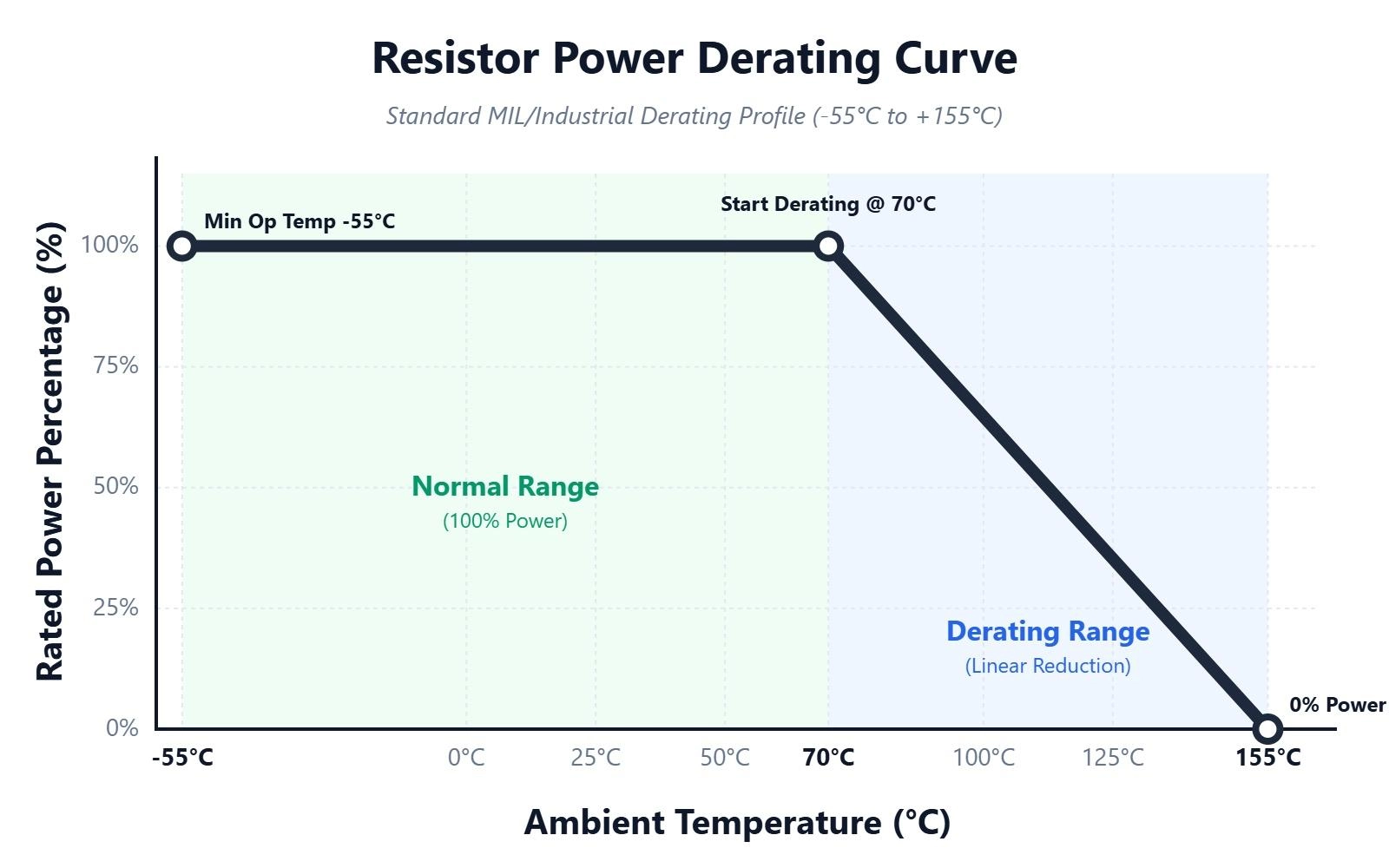
Figure: Resistor derating curve chart illustrating how maximum power dissipation capacity drops linearly as ambient temperature exceeds 70 degrees Celsius.
If your device operates inside a hot, unventilated enclosure at 100°C, a 1/4W resistor might only be capable of dissipating 0.1W. Forgetting to consult the datasheet's derating curve leads directly to thermal runaway, where the resistor gets too hot, its resistance shifts, it draws more current, and ultimately burns out.
PCB Thermal Design Tips for Maximizing Effective Resistor Power Rating
Heat dissipation isn't just about the component; it's heavily reliant on your PCB layout. Because SMD resistors sit flush against the board, the FR4 material and copper traces act as the primary heatsinks. Try these strategies to improve thermal management:
- Maximize Copper Pours: Using wider trace widths attached to the resistor pads significantly increases thermal mass, pulling heat away from the ceramic body.
- Leverage Internal Planes: Using internal copper planes as thermal spreaders significantly increases the effective power handling of SMD resistors.
- Implement Thermal Vias: Adding thermal vias beneath or adjacent to the component allows heat to transfer through the board to internal copper planes or bottom-layer heat spreaders.
- Control Component Spacing: Never cluster multiple high-power resistors tightly together, and keep them far away from temperature-sensitive components like electrolytic capacitors or microcontrollers.
- Optimize Footprints: Ensuring a robust solder fillet is crucial for thermal transfer. Brushing up on solder pad design explained will help you create layouts that naturally wick heat away efficiently.
What Happens If a Resistor Exceeds Its Power Rating?
When a resistor is forced to dissipate more power than its rating allows, the breakdown is rapid and destructive. Common causes of this failure include:
- excessive current
- high ambient temperature
- insufficient copper heat spreading
- ignoring the safety margin
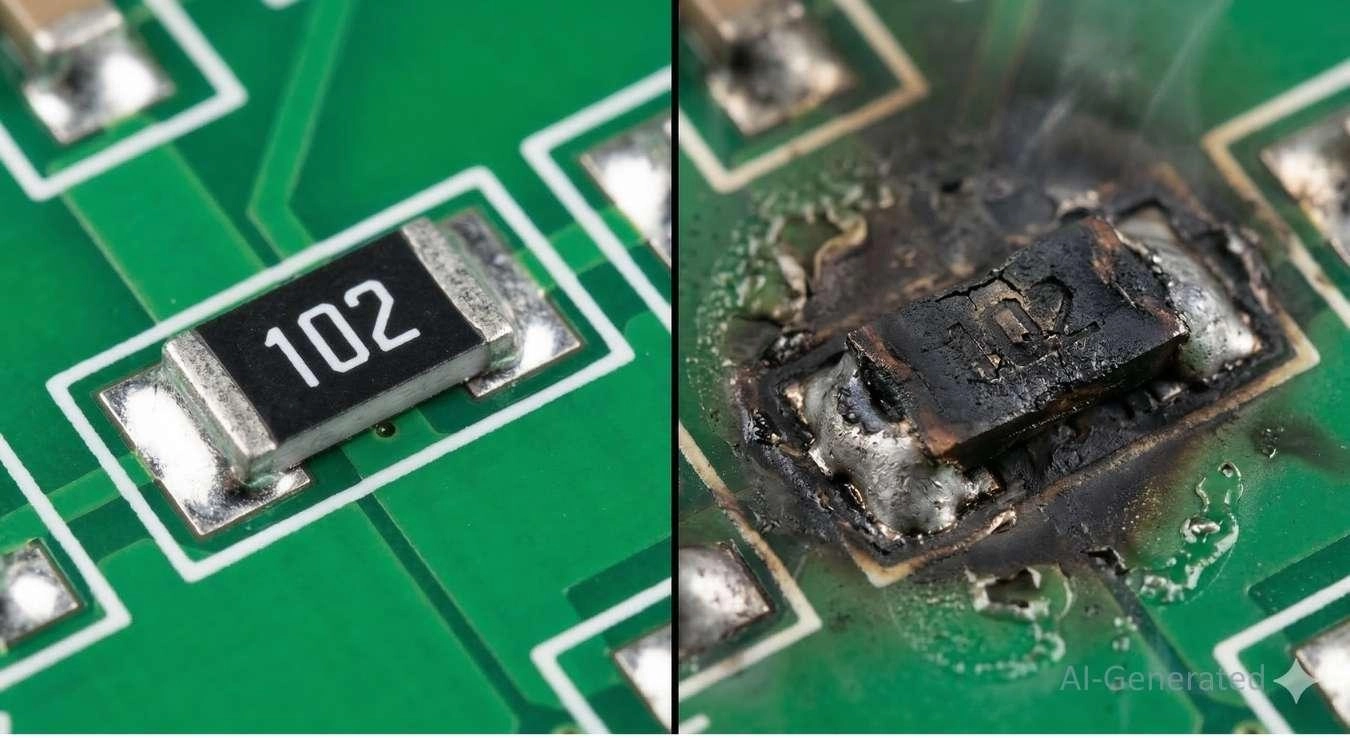
Figure: Burnt surface-mount resistor on a printed circuit board demonstrating severe thermal failure caused by exceeding the maximum power rating.
Initially, excessive heat degrades the internal structure, causing a permanent drift in its resistance value. As temperatures climb, the protective epoxy coating will blister and emit an acrid burning smell. Eventually, the conductive element vaporizes, resulting in carbonization, a scorched PCB surface, and an open circuit that kills the board.
FAQs
Q: Can I use a higher wattage resistor?
Yes, using a higher wattage resistor is perfectly safe and often recommended to establish a better thermal margin. The only downsides are increased component cost and a larger physical footprint on your PCB.
Q: Does resistor size affect power rating?
Absolutely. Physical size directly correlates to surface area. A larger surface area allows the resistor to transfer heat to the ambient air and PCB traces much more efficiently, increasing its wattage capacity.
Q: Is a 0805 resistor always 0.125W?
Not necessarily. While 1/8W (0.125W) is the standard for thick-film 0805 packages, manufacturers also produce high-power thin-film or specialized variants in the same footprint capable of handling up to 0.25W or 0.5W.
Q: Why does a resistor get hot?
Resistors generate heat due to Joule heating. As electrical current (electrons) flows through the resistive material, collisions occur, converting electrical kinetic energy directly into thermal energy.
Q: How can I reduce resistor heating?
You can reduce heating by choosing a higher wattage rating, placing multiple resistors in parallel to split the current load, increasing the copper pour area around the pads, or improving enclosure airflow.
Conclusion
Selecting the correct resistor power rating is just as critical as choosing the right resistance value. By properly calculating I2R, respecting derating curves, applying the 2x safety margin, and utilizing smart PCB thermal design, you ensure your circuits remain stable and reliable under heavy loads. Understanding resistor power rating ensures reliable PCB performance. Once your schematic is thermally sound and your packages are locked in, it’s time to bring your hardware to life.
Get an instant estimate on the Quotation Page and rely on JLCPCB for rapid, high-quality fabrication and assembly.

Popular Articles
• SMD Diode Code Lookup: Full List, Marking Guide & Identification [2026 Guide]
• SMD Resistor Package Sizes: Complete Size Chart, Footprints & How to Choose
• SMD Capacitor Codes: Identification, Markings, and Polarity
• SMD Capacitor Sizes: Complete Size Chart and Selection Tips for PCB Design and Assembly
• How to Solder SMD Components Like a Pro [2026 Updated]
Keep Learning
PoP Package (Package on Package) Explained: Architecture, Assembly, and SMT Challenges
In the race for miniaturization, fitting more processing power into smaller footprints is the ultimate challenge for PCB designers. Package on Package (PoP) technology answers this by integrating logic and memory vertically, becoming the standard for modern mobile processors. However, this 3D architecture demands advanced SMT assembly capabilities beyond standard fabrication. JLCPCB specializes in the high-precision manufacturing required to master these complex stacks. This guide covers how PoP packa......
What Is a PQFP Package? Plastic Quad Flat Package Design, Footprint, and Assembly Guide
The Plastic Quad Flat Package (PQFP) is a widely used IC package in industrial, automotive, and embedded designs. This article provides a practical, engineering-focused guide to PQFP package. It explains how PQFP is built, when it makes sense to use it, how it compares with newer package types, and what designers should consider in terms of footprint design, thermal performance, signal integrity, manufacturing, and reliability. What Is a PQFP Package (Plastic Quad Flat Package)? A Plastic Quad Flat Pa......
Small Outline Integrated Circuit (SOIC): Package, Specs & Uses
As designs transition from legacy through-hole components to high-density Surface Mount Technology (SMT), the Small Outline Integrated Circuit (SOIC) remains the industry standard for operational amplifiers, flash memory, sensors, and microcontrollers. It stands as a testament to balanced engineering, offering a perfect compromise between the miniaturisation demanded by modern consumer electronics and the ruggedness required for industrial applications. This article serves as a definitive engineering ......
A Complete Guide to Surface Mount Device (SMD)
Imagine holding a smartphone in your hand. Inside that sleek device lies a complex network of thousands of miniature components — resistors smaller than a grain of rice, capacitors thinner than a fingernail, and integrated circuits containing millions of transistors. Without Surface Mount Technology (SMT) and its compact Surface Mount Devices (SMDs), none of this would exist. Just a few decades ago, electronics were bulky. Radios filled desks, computers filled rooms, and assembling a circuit meant dri......
Circuit Breaker Types Explained: MCB, MCCB, RCCB, RCBO, ACB, VCB & SF6 Circuit Breakers
A circuit breaker automatically disconnects power when it detects faults such as overloads or short circuits, protecting equipment and reducing fire risk. Different circuit breaker types are designed for different voltage levels, current ratings, and applications, from household distribution boards to high-voltage substations. This guide explains the most common types - including MCBs, MCCBs, RCCBs, RCBOs, ACBs, VCBs, and SF6 breakers and helps you choose the right one for your application. Figure: Ci......
Quad Flat Package (QFP): The Engineer's Guide to Design, Assembly and Thermal Management
What is QFP Package? The Quad Flat Package (QFP) is one of the most popular surface mount technology (SMT) package formats throughout the history of electronic manufacturing. After it became standard in the 1980s, the QFP has been the industry standard for integrated circuits (ICs) with moderate to high pin counts that typically range from 32 to 304 pins, so it was a good alternative for simple SOIC packages and complex Ball Grid Arrays (BGAs) at the same time. Defined by its "gull-wing" leads extendi......