Medical Flex Circuits: Manufacturing, Applications, Materials, and Design Guide
18 min
- What Are Medical Flex Circuits?
- How Are Medical Flex Circuits Manufactured?
- Key Materials Used in Medical Flex Circuits
- Key Design Considerations for Medical Flex Circuits
- Advantages and Applications of Medical Flex Circuits
- Medical Flex Circuits vs Traditional Medical Wiring Solutions
- Choosing a Medical Flex Circuit Manufacturer
- JLCPCB's Medical Flex Circuit Manufacturing Capabilities
- Conclusion
- Frequently Asked Questions
Medical flex circuits made to fit inside a 1.0 mm disposable endoscope, wrap around a hearing aid shell, and sit on a patient's arm for ten straight days. When one fails, it is not a warranty return but a device history file and a regulatory conversation.
In this guide, you will learn:
- What separates a medical flex circuit from a consumer one
- How they are built, tested, and released
- Polyimide, copper, coverlay, and stiffener choices
- Fine line, bend radius, and layer count limits
- What to check before committing to a medical FPC supplier
What Are Medical Flex Circuits?
Definition of Medical Flex Circuits
A medical flex circuit is a flexible printed circuit built on polyimide film for a medical device, fabricated and documented in accordance with medical-grade acceptance requirements. Electrically, it is an ordinary FPC, but what makes it medical is the acceptance class, the material traceability, and the qualification evidence that travels with it.
IPC publishes a dedicated document for this, IPC-6013EM, the Medical Applications Addendum to IPC-6013E. Against a consumer Class 2 build, it adds tighter plating criteria, lot traceability, change notification before a laminate swap, evidence of biocompatibility, and sterilization qualification.
Why Flexible Circuits Are Used in Medical Devices
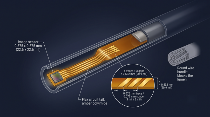
Inside the endoscope shaft, the wiring must bend at the same place as the shaft bends and remain fixed where the shaft is fixed, and must never bind. A round bundle of wires doesn't do any of those three things in a 3 mm tube, and a flat polyimide ribbon does all three.
The second is because of the joint count: each crimp and connector pair can loosen or corrode with repeated cleaning, and an etched trace removes them. The third one is repeatability, since a hand-dressed loom varies from one to another, as does conductor spacing and radiated emissions when the device must be tested per IEC 60601-1-2 for a family of devices.
How Medical Flex Circuits Support Compact Medical Electronics
Miniaturization here is bounded by anatomy: a bronchoscope must fit an airway, a catheter a vessel.
For example, the OmniVision OV6948 image sensor measures 0.575 x 0.575 mm (22.6 x 22.6 mil) and 0.232 mm tall. Packaged as the OVM6948, it fits a disposable endoscope 1.0 mm (39 mil) across, and nothing but a fine line flex tail gets four conductors out of a device that size. A flat 0.07 mm ribbon also leaves the working lumen open.
How Are Medical Flex Circuits Manufactured?
Material Selection and Layer Stackup Design
Material selection is decided by the sterilization cycle before the signals. The choice is adhesive-based versus adhesive-free polyimide laminate, both covered by IPC-4204. A three-layer adhesive-based stack, such as DuPont Pyralux LF, is cheaper and serves to around 200 °C, but its acrylic layer has a Z-axis CTE in the hundreds of ppm/°C and pushes on plated barrels every heat cycle. Adhesive-free laminate such as DuPont Pyralux AP serves up to around 300 °C.
A 25 µm (1 mil) core buys flexibility; a 50 µm (2 mil) core buys tear resistance and manufacturable impedance geometry. A four-layer build at 0.20 to 0.45 mm (7.9 to 17.7 mil) should never sit in a fold.
Precision Circuit Fabrication and Etching Process
Flex fabrication is subtractive, so the fine line limit is set by how far the etchant undercuts sideways. Thicker copper loses more width, which is why minimum trace and space are quoted per copper weight.
- Material issue. Laminate, coverlay, and adhesive lots are recorded against the job traveler.
- Laser direct imaging. LDI scales artwork per panel to chase polyimide movement.
- Develop and spray etch. Copper clears to the polyimide, leaving a trapezoidal conductor.
- Coverlay lamination. Pre-cut polyimide is pressed on under heat; apertures are oversized, so the adhesive never reaches the pad.
- Surface finish. ENIG at 1 or 2 microinches of gold.
- Profiling. Either a UV laser or a punch die brings the part to the outline.
Testing and Quality Inspection for Medical Applications
Every medical flex circuit should leave the factory electrically proven and documented:
- AOI on every conductive layer for nicks and width violations that pass a net test today and open in service.
- 100% net test, the only test that proves every conductor on every unit.
- Microsection coupons for hole wall copper and voids. IPC-6013 Class 3 expects roughly 25 µm average hole wall, copper.
- Flex endurance, IPC-TM-650 Method 2.4.3, for copper fatigue life at your bend radius.
- Ionic cleanliness, IPC-TM-650 2.3.25 or 2.3.28, against the 1.56 µg/cm² benchmark.
Key Materials Used in Medical Flex Circuits
Polyimide Materials for Medical Flexibility and Reliability
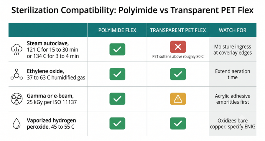
Polyimide film, which most engineers still call Kapton, is the base of essentially every medical flex circuit. With no woven glass reinforcement, it bends without cracking and holds service around 250 to 300 °C. The sterilization method turns that into a specification.
| Sterilization Method | Typical Conditions | Polyimide Flex | Transparent PET Flex | What to Watch |
| Steam autoclave | 121 °C for 15 to 30 min, or 134 °C for 3 to 4 min | Comfortable | Unsuitable, softens above roughly 80 °C | Moisture ingress at coverlay edges |
| Ethylene oxide | 37 to 63 °C humidified gas, then aeration | Comfortable | Acceptable | Acrylic adhesive absorbs EtO, so extend aeration |
| Gamma or e-beam | 25 kGy typical dose under ISO 11137 | Comfortable | Single dose only, embrittles with repeats | Acrylic adhesive yellows before the polyimide does |
| Vaporized hydrogen peroxide | 45 to 55 °C low-temperature cycle | Comfortable | Acceptable | Oxidizes bare copper, so specify ENIG |
Polyimide survives every cycle in that table, so the adhesive inside the laminate is what limits the design. One endoscope camera flex read open on two nets at its fortieth reprocessing cycle: acrylic adhesive had expanded through 134 °C steam and separated the plated barrel. Standard flex-grade polyimide is not qualified for implantation or unrestricted patient contact. Films used that way carry their own ISO 10993 or USP Class VI test files, so biocompatibility is a claim belonging to a documented lot.
Copper Layers for Signal and Power Transmission
Rolled annealed (RA) foil has elongated grains in the plane of the foil, the structure that tolerates repeated folding, while electrodeposited (ED) foil has columnar grains that seed cracks under cyclic strain. Medical signals are also unusually small. A surface ECG trace is 0.5 to 5 mV, and EEG signals run to tens of microvolts, which is why front-end devices such as the Texas Instruments ADS1292R are 24-bit parts. At that level, a copper-to-solder junction behaves as a thermocouple.
| Copper Weight | Foil Thickness | Typical Min Trace/Space | Where It Lands in a Medical Device |
| 0.33 oz | 12 µm (0.5 mil) | 0.076/0.076 mm (3/3 mil) | Endoscope camera tails, catheter sensor leads, electrode arrays |
| 0.5 oz | 18 µm (0.7 mil) | 0.089/0.089 mm (3.5/3.5 mil) | Wearable patch bodies, hearing aid interconnects, and monitor front ends |
| 1 oz | 35 µm (1.4 mil) | 0.10/0.10 mm (4/4 mil) | Infusion pump motor drives, heater elements, and battery runs |
Coverlay and Stiffener Options for Different Applications
Coverlay is the flex equivalent of solder mask, specified under IPC-4203. It arrives as pre-cut polyimide with adhesive, typically 12.5 to 25 µm of film plus 15 to 25 µm of adhesive, with openings drawn about ±0.1 mm (±4 mil) oversize so squeeze-out never reaches a pad. Black film inside an endoscope head absorbs stray light that would lift the photodiode noise floor.
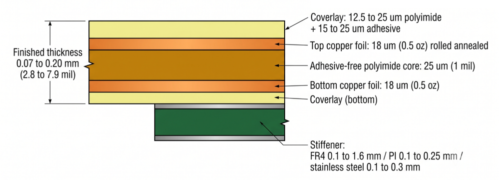
Stiffeners add rigidity where the circuit must not flex, and mixing types is normal: polyimide under a ZIF tail, FR4 under component islands, stainless steel behind ultrasound stacks, and adhesive film to bond the flex to a housing. That adhesive film is the layer most likely to fail an extractables assessment.
Key Design Considerations for Medical Flex Circuits
Miniaturization and Fine Line Circuit Requirements
Medical fine line flex is anything below about 0.10 mm line and space, and the floor depends on the process you are buying. On a conventional subtractive line, 0.076 mm on 0.33 oz copper is routine, with roughly 0.05 mm (2 mil) as an absolute limit reached at a real yield cost.
Sputtered seed copper and semi-additive plating are required below that, a different supply chain and price band. Four conductors (at 0.076 mm traces and spaces) leave that 0.575 mm sensor requiring 0.532 mm, so there is a 0.043 mm margin.
Bend Radius and Dynamic Flexing Performance
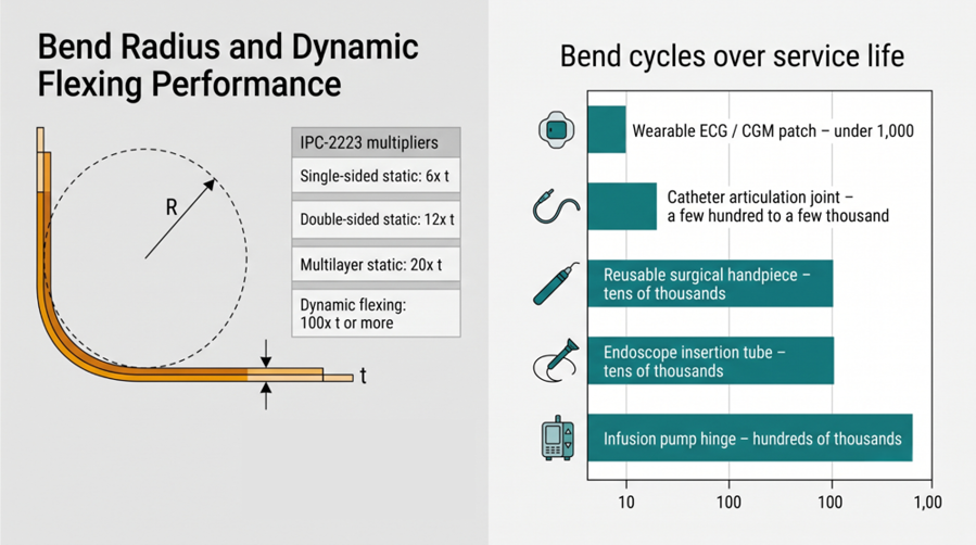
Bend radius decides whether a medical flex circuit reaches the end of its service life. IPC-2223 expresses it as a multiplier of finished thickness: 6x for single-sided static bends, 12x for double-sided static, 20x for multilayer static, and 100x or more for dynamic flexing. Run the arithmetic before the enclosure is frozen. A wearable patch conforms statically, so 6x on a single layer is enough, while catheter joints and pump door hinges want 100x on RA copper. A two-layer flex at 0.20 mm needs a 2.4 mm (94 mil) static radius and a 20 mm dynamic radius, and a 20 to 30% margin pushes that past 25 mm.
Layer Count, Circuit Density, and Reliability Requirements
Bending stiffness scales with the cube of thickness, so a four-layer flex at 0.24 mm (9.4 mil) is roughly eight times stiffer than a two-layer flex at 0.12 mm. Dense multilayer regions and fold zones should never overlap. Three mistakes recur.
Mistake 1: A via inside the bend zone. The plated barrel is a rigid inclusion whose copper knuckle concentrates strain until a crack starts. To fix this: keep vias and pads 1.0 mm (39 mil) clear of the bend, with the coverlay opening set back a further 0.5 mm.
Mistake 2: Writing "Class 3" and assuming it covers medical. It carries none of the qualification or traceability content that your design file will be audited against. To fix this: name IPC-6013EM on the fabrication drawing.
Mistake 3: Ordinary signal spacing across a patient isolation barrier. Two means of patient protection at 250 V typically result in creepage of approximately 8 mm (315 mil) and clearance of 5 mm under IEC 60601-1. To fix this: make the barrier an explicit keep-out on every layer.
Advantages and Applications of Medical Flex Circuits
Compact and Lightweight Design for Medical Devices
The patch, which is worn on the skin, has a modified adhesive that resists the pull of its own weight, so every gram that is cut off will give it more wear time before the edges lift. A 30 x 20 mm two-layer flex to 0.12 mm weighs about 0.15 g, whereas the equivalent eight-conductor loom with two connector housings weighs about 2 g. Flex folds into the geometry, something a rigid board can't do in the hearing aid shell.
Reliable Performance in Flexible and Dynamic Applications
Reliability under motion is the result of a combination of three factors: rolled annealed copper, a copper-free bending axis, and conductors perpendicular to the fold. Miss one, and the assembly fails in the field after passing the bench test. All traces are in the same location across all units, and spacing, impedance, and coupling are repeatable, thereby enabling controlled-impedance video from a moving imaging head.
Wearable Devices, Diagnostic Equipment, and Monitoring Systems
Use this mapping to convert a device requirement straight into a flex build.
| Medical Device | What the Flex Does | Typical Build | Dominant Requirement |
| Wearable ECG patch, 14-day wear | Electrodes to the analog front end | 1 to 2 layer, 0.07 to 0.12 mm, 0.5 oz | Low mass, skin-safe film, microvolt noise floor |
| Continuous glucose monitor | Sensor wire to the BLE radio and battery | 2-layer, 0.12 mm, 0.33 oz | Miniaturization, 10 to 15 days sealed |
| Hearing aid | Receiver and microphone lines, folded into the shell | 2-layer, 0.07 to 0.11 mm, 0.33 oz | Volume rather than area |
| Disposable endoscope camera | Four conductors from the image sensor up the shaft | 1 layer, 0.07 mm, fine line | Fits a 1.0 mm lumen, single-use |
| Ultrasound transducer probe | Fans array elements back to the cable | Multilayer fine line | Element pitch, crosstalk |
| Infusion pump | Door sensors, motor drive, interface board | 2-layer, 0.12 to 0.20 mm, 1 oz | Hundreds of thousands of hinge cycles |
| Patient monitor front end | Bridges the isolated applied part to the main board | 2-layer with an isolation gap | IEC 60601-1 creepage and clearance |
Medical Flex Circuits vs Traditional Medical Wiring Solutions
Flex Circuits vs Wire Harnesses
A discrete harness wins on two axes: no tooling and easy field modification. Neither survives design freeze on a controlled build.
- Consistency: Flex is etched from one artwork, so EMC results from one unit predict the fleet.
- Failure sites: Continuous copper has no crimps, and crimp relaxation is a classic field failure.
- Reprocessing: One sealed polyimide body wipes down; wire bundles trap fluid and bioburden.
- Documentation: One drawing and one lot record, against wire, terminal, and connector lots.
Flex Circuits vs Rigid PCBs
Neither technology replaces the other, and the strongest medical designs use both. Rigid FR4 is cheaper per square centimeter and supports far more layers.
- Choose rigid for the main processing board, the power supply, and anything mounted flat.
- Choose flex wherever the circuit must fold into a shell, follow a shaft, or cross a hinge.
- Choose rigid-flex for rigid-component islands and flexible interconnect in a single part.
Choosing a Medical Flex Circuit Manufacturer
Manufacturing Capability and Quality Control
Match a supplier's published limits against your worst feature, never your average one. Ask for minimum trace and space at your copper weight, supported layer counts, and profile tolerance. Then ask how they prove the board is good: 100% net testing, AOI on every conductive layer, microsection coupons, and a stated IPC-6013 class.
Material Options and Customization Support
A genuine flex shop offers choices rather than one recipe. Confirm they stock both adhesive and adhesive-free polyimide, both RA and ED copper, and a range of stiffener materials. The question separating a medical-capable supplier from a merely fast one is change control. Consumer fabs re-qualify laminate suppliers without telling anyone, which destroys the verification evidence behind a medical device.
Prototype and Production Manufacturing Support
Medical programs iterate slowly and then freeze hard, so design-verification cadence sets the schedule. At a 4 to 5 day flex lead time, you can run three or four revisions inside one sprint, while a four-week specialist lead time gives you one. Confirm three things:
- Whether prototypes and production run on the same laminate, copper, and process window.
- Whether material lot numbers are recorded and reportable against your order.
- Whether stiffener, coverlay, and profile tooling carry to volume unchanged.
JLCPCB's Medical Flex Circuit Manufacturing Capabilities
JLCPCB is a general-purpose PCB and FPC manufacturer rather than a medical device contract manufacturer, and it does not publish ISO 13485 certification or biocompatibility test files. Read what follows as fabrication capability, not regulatory clearance: it fits early development, design verification builds, and non-patient-contact hardware.
Advanced LDI Technology for High-Precision FPC Production
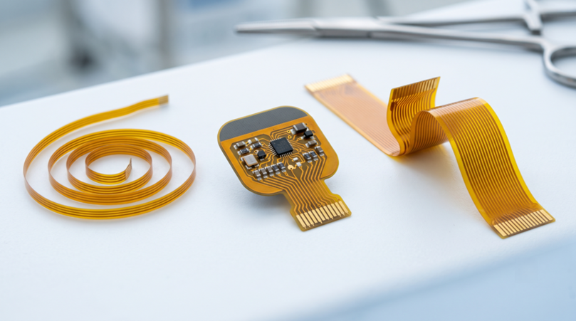
Flex lines are imaged with dry film and laser direct imaging, which allows per-panel compensation for polyimide movement and keeps registration tight on double-sided work. That supports the 0.076/0.076 mm minimum trace and space on 0.33 oz copper listed earlier, with an absolute limit of 0.05/0.05 mm.
Hole diameters run 0.1 to 6.5 mm (4 to 256 mil) at ±0.08 mm, the minimum via hole is 0.3 mm, and the trace width tolerance is ±20%, which sets impedance repeatability. Laser cutting holds ±0.05 mm, and the 234 x 490 mm (9.2 x 19.3 in) panel decides nesting efficiency and part cost.
Adhesive-Free PI Material and Multiple Stiffener Options
The standard substrate is adhesive-free polyimide with 25 µm and 50 µm dielectric. Transparent PET at 36 µm with around 85% transmittance is available where optical clarity matters more than heat resistance, meaning single-use, low-temperature-sterilized assemblies only.
Finished thickness runs from 0.07 to 0.20 mm for one- and two-layer builds on 25 µm polyimide, from 0.12 to 0.19 mm on the 50 µm core, from 0.14 to 0.24 mm for PET, and from 0.20 to 0.45 mm for four-layer stacks. Stiffeners cover polyimide at 0.1 to 0.25 mm, FR4 at 0.1 to 1.6 mm (4 to 63 mil), stainless steel at 0.1 to 0.3 mm, and adhesive films from 0.05 to 0.13 mm, with a stiffened thickness tolerance of ±0.05 mm that decides whether a tail lands inside a ZIF clamp window.
Flexible Circuit Layer, Surface Finish, and Customization Options
Supported builds are 1-, 2-, and 4-layer builds. Rigid-flex is not in the standard range, so a design that needs rigid islands must be split into a flex part and a separate rigid board.
Copper comes in 12, 18, and 35 µm thicknesses, trading fine-line capability against current capacity. Coverlay is available in yellow, black, white, and transparent, with an ENIG finish and 1 or 2 microinches of gold, flat for fine-pitch reflow and tolerant of alcohol wipe-down.
Rapid Prototyping and Scalable Manufacturing Support
Flex orders start at 5 pieces with 4- to 5-day lead times, and every order runs an automated DFM check that flags spacing violations, undersized holes, and coverlay opening problems, and a fix still costs nothing. One mechanical oversight can scrap the whole batch, so feedback is worth more on flex than on any rigid board.
Flying probe testing is offered as a free random test with a minimum 99% pass rate, or as a full test giving 100% net coverage, free below 8,000 test points per board, and $40.74/m² above that. Upload your Gerbers, drill file, and a fabrication drawing showing coverlay openings, stiffener positions, and bend zones to get an instant flex PCB quote, with components pulled from the JLCPCB parts library.
Conclusion
Medical flex circuits reward engineers who treat them as mechanical and regulatory components that happen to conduct electricity. Whether the device survives in the field often depends less on the circuit itself than on decisions made early in the design: choosing a laminate that can withstand the required sterilization cycle, calculating the bend radius before the enclosure is frozen, and specifying an acceptance class on the drawing that matches the standard against which the design will ultimately be audited.
Make those decisions in the right order: choose the substrate based on the sterilization method, set copper weight according to current requirements and noise performance, determine layer count from routing needs, and only then verify that the finished stack-up can still bend within the mechanical limits of the device.

Frequently Asked Questions
What are medical flex circuits?
Medical flex circuits are flexible printed circuits built on polyimide film for medical devices, fabricated to medical-grade acceptance requirements such as IPC-6013 Class 3 and the IPC-6013EM addendum. What makes them medical is the acceptance class, the traceability, and the qualification evidence behind them.
Why are flexible circuits used in medical devices?
Because medical hardware is bound by anatomy and by motion, flex circuits fold into shells and shafts; no rigid board fit. Remove the crimps that fail over years of cleaning, and deliver identical conductor geometry on every unit.
What materials are used in medical flex circuits?
The core stack is polyimide film, copper foil, and an adhesive-coated polyimide coverlay. Adhesive-free laminate, such as DuPont Pyralux AP, is preferred wherever sterilization is repeated, and copper is rolled annealed for bending or electrodeposited for static builds.
What is FPC used for in medical applications?
FPC carries electrode signals in wearable ECG and glucose patches, links image sensors to endoscope shafts, folds circuitry into hearing aid shells, fans element arrays in ultrasound probes, and connects sensors inside infusion pumps.
How can I get a medical flex circuit quote?
Export Gerbers, a drill file, and a fabrication drawing showing layer stackup, copper weight, coverlay openings, stiffener positions, and bend zones. Upload that package and select substrate and finished thickness for pricing, plus a DFM report.

Popular Articles
• Choosing the Right Bend Radius for Durable Flexible PCBs
• Flexible Meets Durable: Understanding Rigid-Flex PCB Technology
• PCB Stiffeners: An Essential Requirement for Flexible Circuits
• The Ultimate Guide to Flexible PCB: Types, Design, and Applications
• 45 Must-Know Flex PCB Design Tips You Can't Afford to Miss!
Keep Learning
Choosing the Right Bend Radius for Durable Flexible PCBs
Key Takeaways Mastering the bend radius is essential for reliable flexible PCB design. Following IPC-2223 guidelines, maintain a minimum of 6× total thickness for static bends and 100× for dynamic applications, while using thinner RA copper, adhesiveless polyimide, staggered traces, and cross-hatched patterns in flex zones. Proper material selection, layer stackup optimization, and adequate clearance from stiffeners can dramatically extend flex life and prevent premature trace cracking or delamination......
Flex PCB Stackup Design Guide: Layers, Materials & Reliability
Key Takeaways A reliable flex PCB starts with the right stackup design. The layer structure, material selection, and copper arrangement directly affect flexibility, bend life, electrical performance, and manufacturing reliability. This guide explains single-sided, double-sided, and multilayer flex PCB stackups, including polyimide materials, coverlay, copper types, and key design considerations for creating durable flexible circuits with JLCPCB. Did you ever wonder how a foldable phone can last for 20......
Flexible Meets Durable: Understanding Rigid-Flex PCB Technology
In the rapidly evolving world of electronics, the demand for smaller, more reliable, and more versatile devices continues to grow. To meet these demands, engineers and designers are increasingly turning to Rigid-Flex PCBs. The circuit boards combine rigid and flexible substrates into a single interconnected structure. This combination allows for complex designs that can bend and flex in specific areas while maintaining rigidity in others. To manufacture rigid flex PCBs, IPC offers advice and best prac......
PCB Stiffeners: An Essential Requirement for Flexible Circuits
A printed circuit board stiffener plays an important role when it comes to offering mechanical support to a PCB. They are particularly helpful for flexible circuit boards, that given their name, are flexible and in need of stiffness in certain places. Stiffeners are particularly required when components are placed in a flex zone & the weight of these components stresses the flex material. These components provide a rigid connection from the flexible portion to the solid board. This solidity makes appl......
The Ultimate Guide to Flexible PCB: Types, Design, and Applications
Key Takeaways JLCPCB 1–4 Layer Flex PCB: Supports 1 to 4-layer FPCs with polyimide (PI) substrates and trace/space down to 3/3 mil. Stiffener Selection: Use PI (0.1–0.25mm) for ZIF connectors, FR4 (0.1–1.6mm) for SMT support, and Stainless Steel (0.1–0.3mm) for high rigidity. Layout Optimization: Use cross-hatched copper ground planes and stagger 2-layer traces to eliminate the "I-Beam effect." Surface & Protection: Combine Immersion Gold (ENIG 1u"/2u") for SMT planarity with flex coverlay to protect ......
Medical Flex Circuits: Manufacturing, Applications, Materials, and Design Guide
Medical flex circuits made to fit inside a 1.0 mm disposable endoscope, wrap around a hearing aid shell, and sit on a patient's arm for ten straight days. When one fails, it is not a warranty return but a device history file and a regulatory conversation. In this guide, you will learn: What separates a medical flex circuit from a consumer one How they are built, tested, and released Polyimide, copper, coverlay, and stiffener choices Fine line, bend radius, and layer count limits What to check before c......