
FPC Connector Guide: Types, Pitch & Reliability
12 min
- Introduction to FPC Connectors
- Understanding FFC and FPC Connector Types
- Key Selection Factors for FPC Connectors
- Reliability Considerations in FPC Connector Design
- PCB Design Considerations for FPC Connectors
- JLCPCB's Expertise in PCB Assembly for FPC Connectors
- Frequently Asked Questions (FAQ)
Key Takeaways
Choosing the right FPC connector is critical for reliable flexible electronic designs. Connector type, pitch, pin count, stiffener thickness, and PCB layout all affect signal integrity and mechanical durability. By understanding FPC connector selection and design considerations, engineers can reduce connection failures and achieve reliable assembly results with JLCPCB.
As you know, the electronics world is getting smaller; nowadays, the devices need to be thin and light. All the parts should be integrated in a good manner; that’s how the importance of the PC connector came into the market. They are flexible ribbon-type cables that get dozens of signals to flow through a moving joint. The flexible flat cable is extremely thin, and the component that secures it is the FPC connector. It's one of the things that nobody talks about until it breaks.
They are small and repeatable, making them ideal for foldable phones, automotive dashboards, and more. If not the correct one is chosen, it can create intermittent issues that can be tricky to troubleshoot. What are FPC connectors, the difference between FPC and FFC connectors, important considerations for choosing the right pitch and the required number of pins, and reliability and PCB design considerations will be discussed. By the conclusion of it, you'll be capable of confidently defining and planning an FPC connector.
Introduction to FPC Connectors
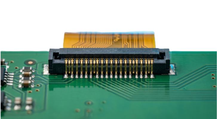
FPC Connectors are board-mounted connectors that are used to connect a Flexible Printed Circuit (FPC) or Flexible Flat Cable (FFC) to a rigid PCB. The connector allows the flex to be inserted and clamped instead of soldered directly, allowing for a serviceable and repeatable joint. Surface-mount devices are used in almost all the new designs these days. They can be arranged in a low-profile, fine pitch configuration, which is ideal for today's portable electronics with high layout density and limited space.
FPC Connector Meaning in Modern Electronic Devices
In simple terms, the FPC connector is used to connect two worlds: the rigid motherboard and the flexible cable, which has to be bent, folded, or routed around tight corners. The connector ensures mechanical retention as well as reliable electrical contact, but without solidly bonding the two. It's a docking station for a thin ribbon cable.
The flex is inserted, locked down, and dozens of signals pass over the interface, including power, data, display lines, touch sensing, etc. The joint is removable, allowing the manufacturers to replace or repair modules, rather than the entire board. This serviceability is a key factor behind why FPC connectors reign supreme in display and camera modules. In the event of a cracked screen, it can be replaced at the connector level without having to rework solder connections through a microscope.
Common Applications in Consumer and Industrial Electronics
FPC and FFC connectors are found virtually wherever flexibility and density are required. They are used in both HV products and critical industrial applications.
- Smartphones and tablets: display panel, touch digitizer, camera module, and fingerprint sensor.
- Laptops, monitors: LCD/OLED panel connector and keyboard membranes.
- Automotive: instrument clusters, infotainment displays, and ADAS camera links.
- Medical devices: Handheld diagnostic devices and imaging probes.
- Industrial control: HMI panels, printers, robotics, and other applications in which cables flex when in use.
Understanding FFC and FPC Connector Types
The term "FFC" is sometimes used in place of “FPC” and the connectors are physically identical. However, the cables they receive are not exactly the same, and knowing the difference can help you to avoid specification errors. Connectors come in a wide variety of connector pitch sizes, from ultra-thin pitch 0.3mm for wearables to rugged 1.0mm pitch for industrial applications. Let's examine the major categories.
Differences Between FFC and FPC Connectors
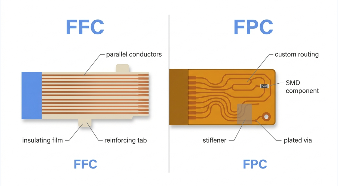
A Flexible Flat Cable (FFC) is a basic, mass produced cable consisting of flat copper conductors, sandwiched between two insulating film layers. It's nothing more than a ribbon, cheap, uniform, and with only possible straight parallel traces.
A Flexible Printed Circuit (FPC), on the other hand, is a flexible circuit board that is custom-made and etched. May contain complex routing, bends, mounted components, stiffeners, and variable-width traces. This is because often the contact pitch and insertion thickness are what are important at the interface, and an FFC and FPC connector will accept both.
ZIF and Non-ZIF Connector Structures
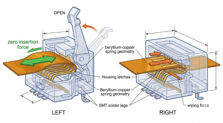
A ZIF (Zero Insertion Force) connector features an actuator, a flip-up or slide-back lever, that opens the contacts before they are inserted into the connector. The cable is dropped in with no effort, and the actuator closes to clamp the cable. This helps to prevent the contacts from being worn down and the pins from bending due to delicate fine-pitch contact.
A non-ZIF (Low Insertion Force) connector does not have a separate actuator. The cable is pressed directly on the spring contacts, and resistance is created during insertion. These are easier and less expensive, but put more strain on the contacts each time a mating cycle occurs.
- The advantages of ZIF: Fine pitch (0.3-0.5mm), higher mating-cycle life, gentle on contacts.
- Non-ZIF benefits: reduced part count, rapid assembly, reduced cost for coarse pitch, and low cycle counts.
Key Selection Factors for FPC Connectors
Pitch Selection and the 0.5mm Industry Standard
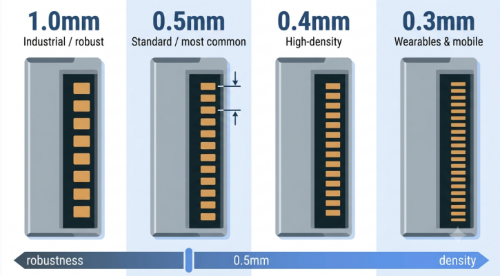
The distance between the centers of the adjacent contacts is defined as pitch. Common FPC connector pitch values are 1.0mm, 0.8mm, 0.5mm, 0.4mm, and 0.3mm. The smaller the pitch, the more conductors can be fit into the smaller width — and the more stringent the manufacturing tolerance and contact reliability. The 0.5mm pitch has become the done thing in terms of industry standard for consumer electronics. It finds a happy medium between density for display/camera modules and coarseness for regular SMT line assembly and tolerances on flex-cables.
| Pitch (mm) | Typical Application | Relative Robustness |
|---|---|---|
| 1.0 | Industrial, power, legacy boards | High |
| 0.5 | Smartphones, displays, cameras (standard) | Balanced |
| 0.4 | High-density modules | Moderate |
| 0.3 | Wearables, ultra-compact devices | Demanding |
Pin Count, Orientation, and Mounting Considerations
The number of conductors (called the pin count) is selected after the pitch. That depends on your signal budget: display lines, power, and ground returns and sideband control signals. Typical range is between 4 and 60 or higher pins. Orientation is also important since connectors are available in vertical (cable exits perpendicular to the board) and horizontal/right-angle (cable exits parallel to the board). Right-angle, top/bottom contact versions allow routing of flex flat against the chassis.
- Specify your signal count and a few extra pins for grounds and/or future expansion.
- Select top-contact, bottom-contact, or dual-contact, according to the side of FPCs on which the exposed pads are located.
- Select orientation to simulate the actual routing of the cable in the enclosure.
- Check that the thickness of the cable (usually 0.20-0.30mm) falls within the acceptable range of the connector.
- Review mounting attributes like metal hold-down tabs for the connector body, which attaches to a PCB for increased pull strength.
Reliability Considerations in FPC Connector Design
The connector is only as good as the connection it holds throughout the lifespan of the product. Reliability is no joke when it comes to FPC connectors, as they are always subjected to moving, vibrating, and thermally cycling conditions. The majority of failures in the field are not catastrophic failures, but rather intermittent failures due to contact wear, fretting, or poor retention. That is significantly less expensive than warranty returns; designing for these failure modes up-front is much better.
Mechanical Durability and Mating Cycle Performance
Each connector has a rated mating cycle count, or the number of times the connector can be inserted and removed before deterioration of the contact resistance. Contacts in ZIF connectors have a higher cycle rating because they're not rubbed during insertion. For most consumer products, the cable is mated once at the factory, and not touched again, and even 20 cycles is more than enough. For repair or industrial products, higher cycle gold-plated components should be identified.
Preventing Connection Failure and Contact Wear
Inconsistent connection failure is the problem with flex interconnects. The most frequent causes are insufficient insertion length, dirt, and mechanical stresses on the contacts. Avoid these problems by adhering to some effective practices:
- Make sure the cable is fully inserted and the latched connection is secure: When the cable is not latched all the way, it is the number one reason for intermittent opens.
- Use a stiffener on the FPC contact end to keep the exposed pads flat and apply even pressure.
- Secure with hold-down tabs to prevent contacts from becoming loose over time due to cable tension.
- Mention gold plating in corrosive or damp conditions to prevent corrosion from fretting.
- Offer strain relief close to the connector, allowing the repeated flexing to occur outside of the contact area.
PCB Design Considerations for FPC Connectors
Footprint Layout and Stiffener Thickness Matching
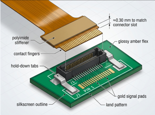
Follow the manufacturer's recommended footprint all the time. Per IPC-7351 land-pattern principles, the land pattern must be identical to the connector's contact and hold-down geometry, and there is no margin for error when working with fine-pitch parts. Be careful about matching the thickness of stiffeners carefully. Typically, the FPC end that fits into the connector will have a stiffener (a small piece of stiff material such as polyimide or FR4) bonded to it. This stiffener increases the thickness of the insertion to the connector window, usually about 0.30mm.
- Check the datasheet for the range of acceptable cable thickness for the connector.
- Explain the FPC stiffener thickness to target the total insertion thickness to be in the middle value rather than the extreme value.
- Do not solder mask openings or paste apertures that deviate from the recommended footprint, which can cause bridging on fine pitch.
- Give a good mechanical keep-out to allow the actuator to open and close.
Signal Integrity and Mechanical Stress Management
Electrically, the flex-to-connector transition must be considered a controlled-impedance discontinuity. On high-speed interfaces such as MIPI display or camera interfaces, differential pairs must be length matched, and a continuous reference plane must be maintained up to the connector. Mechanically, the objective is to prevent solder joints and contacts from being under stress. Here are some tips that will help a lot:
- Make sure the connector is facing the direction where the cable can be placed, and not into the wall, which will result in a tight bend at the contact.
- Secure the flex with adhesive or clip a few millimeters beyond the connector to take pull stresses.
- Include ground stitching where high-speed pins exist to include tidy return paths across the transition.
- Do not put the connector at the edge of the board where the depaneling stress on the panel or handling can fracture the solder joints.
JLCPCB's Expertise in PCB Assembly for FPC Connectors
Fine-pitch FPC connectors require a high level of process control during assembly. With a 0.3mm pitch part, there is little room for paste misregistration or placement offset (which is why a capable manufacturing partner is important). With precision manufacturing and full SMT assembly, modern PCB manufacturers such as JLCPCB deliver boards along with connectors that are ready to use. This is important because the footprint, fabrication tolerance, and assembly accuracy must all intersect to ensure a good joint.

Engineering Review and Manufacturing Quality Control
Prior to production, an engineering review (DFM check) identifies issues such as solder mask slivers that are too small between fine pitch solder pads or footprint mismatch, the very issues that cause FPC connectors to fail. If you catch them at this stage, it is no cost compared to a failed build. Automated Optical Inspection (AIO) checks placement, polarity, and solder joint quality on the line to IPC-A-610 standards. In the case of the densest connectors, this inspection layer is what makes the difference between a high-yield batch and a batch that has some intermittent failures, resulting in boards you can count on in the field.

Frequently Asked Questions (FAQ)
Q: What is the difference between an FFC and an FPC connector?
Ans: The connectors themselves are very similar, but the cables differ. An FFC (Flexible Flat Cable) is a simple ribbon of parallel laminated conductors, while an FPC (Flexible Printed Circuit) is a custom-etched flex circuit that can include complex routing and mounted components. Many connectors accept both since pitch and insertion thickness are what matter at the interface.
Q: Why is 0.5mm the most common FPC connector pitch?
Ans: The 0.5mm pitch balances density and manufacturability. It is fine enough for display and camera modules yet coarse enough to be robust on standard SMT lines and forgiving of normal cable tolerances. Finer pitches like 0.3mm save little width while sharply increasing manufacturing sensitivity.
Q: What is a ZIF connector, and when should I use one?
Ans: A ZIF (Zero Insertion Force) connector has an actuator that opens the contacts before the cable is inserted, then clamps them shut. This protects delicate fine-pitch contacts from wear, so ZIF is the preferred choice for 0.5mm and finer pitches and for designs needing more mating cycles.
Q: How do I prevent intermittent connection failures with FPC connectors?
Ans: Ensure the cable is fully inserted and the latch is closed, add a stiffener so the contact pads stay flat, and use the connector's hold-down tabs to keep cable tension off the contacts. Specifying gold plating and adding strain relief further reduces fretting and contact wear.

Popular Articles
• 45 Must-Know Flex PCB Design Tips You Can't Afford to Miss!
• Choosing the Right Bend Radius for Durable Flexible PCBs
• FPC Design Rules: 13 Safety Distances You Can’t Ignore
• Mastering PCB Stiffeners: A Comprehensive Guide to Types, Applications, and Design Best Practices for Flexible Circuits
• How Flex Coverlay Protects and Enhances Flexible PCB Durability
Keep Learning
Flex PCB Manufacturing Process: From Prototyping To Mass Production
Flexible Printed Circuit Board commonly known as flex PCBs are a revolutionary step in modern electronics that offer compact, lightweight, dynamic and precise designs. Flex PCBs are designed to bend, twist, and fold, which rigid boards are incapable of. These characteristics have led to their widespread adoption in industries like wearable technology to consumer electronics to aerospace and medical technologies. With demands increasing day by day for miniaturized and ergonomic product designs, underst......
45 Must-Know Flex PCB Design Tips You Can't Afford to Miss!
Achieving perfection in product design requires a careful balance between meeting design requirements and manufacturing standards. However, when it comes to flex PCB (FPC) design, many engineers find themselves at a loss, unsure of where to begin. In this insightful guide, we will delve into 45 essential design guidelines for FPC. By the end, you'll have the knowledge and confidence to navigate the complexities of flex PCB design. Outline and Drilling 1. The minimum distance from through-holes to the ......
Choosing the Right Bend Radius for Durable Flexible PCBs
Key Takeaways Mastering the bend radius is essential for reliable flexible PCB design. Following IPC-2223 guidelines, maintain a minimum of 6× total thickness for static bends and 100× for dynamic applications, while using thinner RA copper, adhesiveless polyimide, staggered traces, and cross-hatched patterns in flex zones. Proper material selection, layer stackup optimization, and adequate clearance from stiffeners can dramatically extend flex life and prevent premature trace cracking or delamination......
FPC Connector Guide: Types, Pitch & Reliability
Key Takeaways Choosing the right FPC connector is critical for reliable flexible electronic designs. Connector type, pitch, pin count, stiffener thickness, and PCB layout all affect signal integrity and mechanical durability. By understanding FPC connector selection and design considerations, engineers can reduce connection failures and achieve reliable assembly results with JLCPCB. As you know, the electronics world is getting smaller; nowadays, the devices need to be thin and light. All the parts sh......
Flex PCB Design Guide: Preventing Mechanical Failures
Key Takeaways Reliable flex PCB design requires more than electrical performance. Proper bend radius control, trace routing, via placement, stiffener selection, and DFM considerations are essential to prevent mechanical failures such as copper cracking and delamination. By following proven flexible PCB design practices, engineers can improve durability and achieve reliable production results with JLCPCB. Ever wonder how the circuit in a foldable phone, fitness tracker, or camera module manages to rema......
Flex PCB Prototyping Guide: Materials & Design Tips
Key Takeaways A reliable flex PCB prototype requires more than just a working circuit. Material selection, bend radius control, copper design, panelization, and stiffener choices directly impact flexibility, durability, and manufacturing success. By following proper flexible PCB prototyping practices, engineers can reduce design risks and smoothly transition from prototypes to production with JLCPCB. Ever wonder how the circuit in a smartwatch, a foldable phone, or a camera module can take the shape? ......