
How to Solder Wires to a Circuit Board Properly: Step-by-Step Guide
13 min
- Soldering Tools and Materials Required for Soldering Wires to a Circuit Board
- Preparation Before Soldering Wires to a Circuit Board
- How to Solder Wires to a Circuit Board (Step-by-Step)
- Practical Wire Soldering Tips for Stronger Joints
- Special Tips for Soldering Wires to Surface Mount Pads
- Common Problems When Soldering Wires to a Circuit Board
- Troubleshooting and Rework Tips for Wire Soldering
- Inspection Checklist After Soldering Wires to a Circuit Board
- Conclusion
- FAQ
Learning how to solder wires to a circuit board is a fundamental skill for electronics repair, prototyping, and PCB assembly. Whether you are attaching power leads, signal wires, or test connections, a weak solder joint can cause intermittent failures, lifted pads, or long-term reliability issues.
In this step-by-step guide, you’ll learn the correct tools, preparation methods, and soldering techniques needed to create strong, clean, and reliable wire-to-PCB connections.
From preparing the wire and PCB pad to inspecting the finished joint and troubleshooting common problems, this article walks you through the entire process in a clear, practical way.
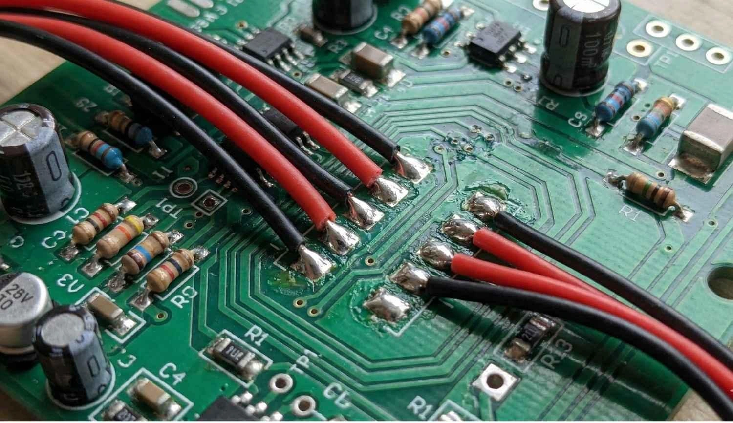
Figure: Red and black wires soldered to a circuit board
Pro Tip: Manual soldering is a must for testing, but it is not scalable. JLCPCB PCB assembly services provide the precision and consistency of automation that hand soldering cannot deliver for production runs of 5 units or 10,000.
Soldering Tools and Materials Required for Soldering Wires to a Circuit Board
A solder joint equivalent to IPC-class can only be obtained with tools that have excellent thermal recovery and stability.
Essential Soldering Tools
- Solder Wire: Leaded (Sn63/Pb37) is the most user-friendly option (melting point is 183°C). Lead-Free (SAC305) is more environmentally friendly but demands a higher temperature (217°C).
- Temperature-Controlled Iron: A station maintaining 320°C – 380°C is essential. Avoid non-adjustable sticks.
- Chisel Tip: It is recommended in comparison to conical ones. The heat is transferred very efficiently through the flat surface to both the wire and the pad at the same time.
- Flux: Keep a flux pen or gel nearby. Flux makes the solder flow by removing the oxides that hinder the process of "wetting" the solder.
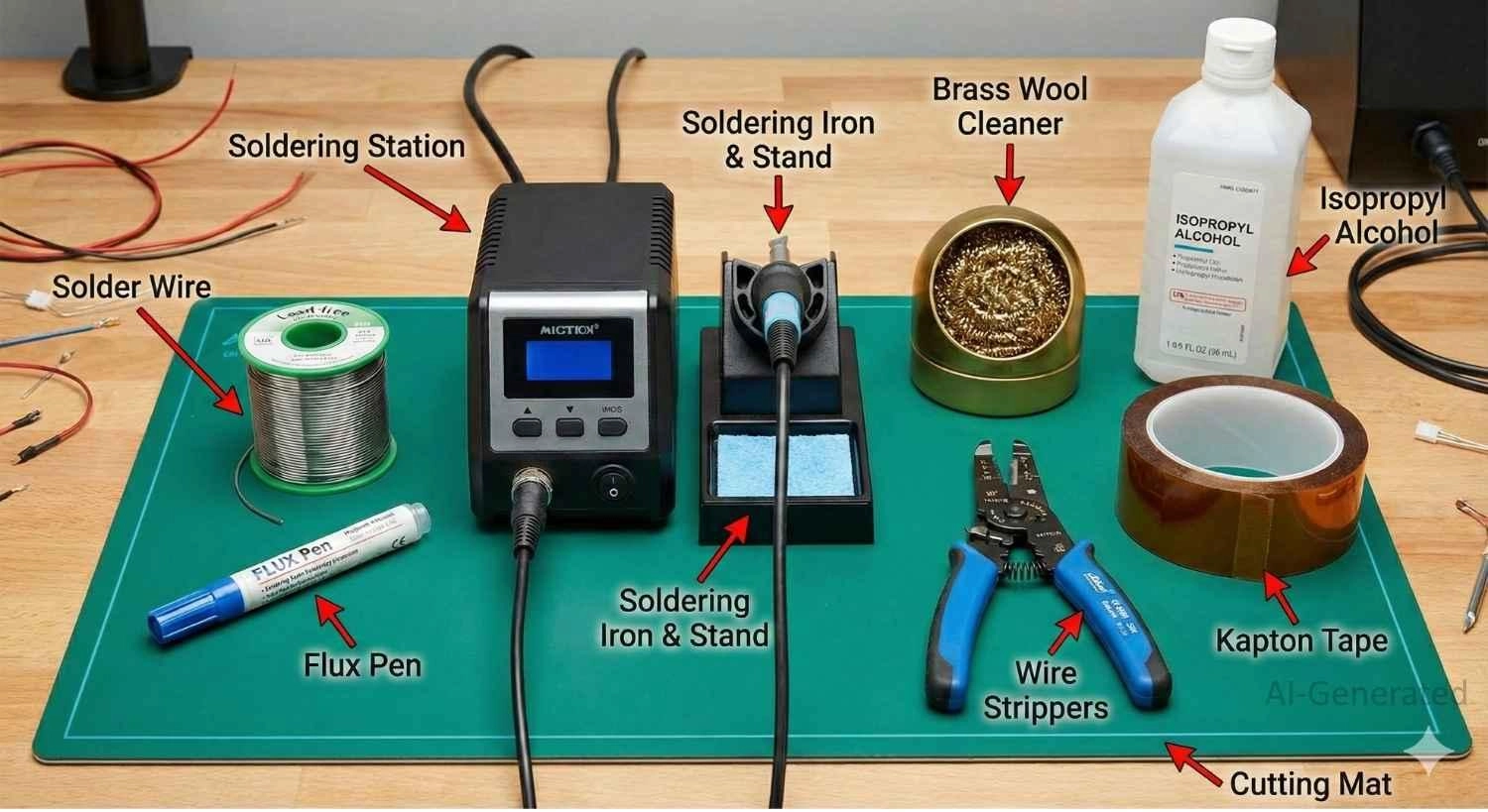
Figure: Complete set of electronics soldering tools, including soldering station, flux, solder, etc.
Optional but Recommended Soldering Tools
- Isopropyl Alcohol (IPA): Very pure (90%+) for removing residues left by glue that is difficult to remove.
- Kapton Tape: Heat-resistant polyimide tape to secure wires or shield nearby components.
- Helping Hands: A weighted base with clips to stabilize the PCB and wire.
Soldering Tool | Function | Why It Matters |
|---|---|---|
Flux Pen | Chemical cleaning | Gets rid of oxidation, thus very fast solder flow. |
Chisel Tip | Heat transfer | High thermal mass heats the joint quickly, protecting the PCB. |
Wire Strippers | Insulation removal | Avoids the situation of nicking strands, which is the cause of wire fatigue. |
Brass Wool | Tip cleaning | Cleans oxidation without thermally shocking the iron tip. |
Preparation Before Soldering Wires to a Circuit Board
Effective preparation eliminates the problems of melted insulation and cold joints. Pre-tinning takes the time of the whole soldering process to less than 2 seconds.
How to Prepare the Wire
- Strip Cleanly: Strip off 2-3mm of insulation very carefully, so that no strands are cut. Nicks create stress risers that lead to wire breakage.
- Twist Strands: Tightly twist the strands of the wire to make sure that "bird-caging" doesn't happen. The strands that are not tightened can cause short circuits that are even dangerous.
- Pre-Tin: Apply solder to the twisted strands before touching the PCB. The solder should permeate the wire, protecting it from oxidation and ensuring instant bonding.
How to Prepare the PCB Pad
- Clean: Wipe oxidized pads with IPA.
- Flux: Apply a small drop of flux.
- Pre-Tin: For soldering wires without holes, melt a small "pillow" of solder onto the pad. This acts as the bonding agent, freeing your hands during the final step.
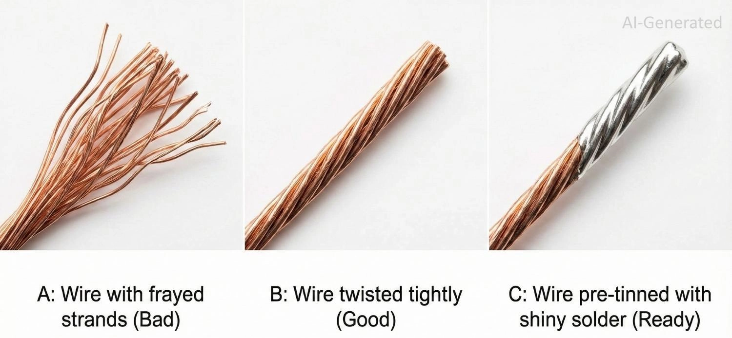
Figure: Proper wire preparation for soldering: twisting strands and pre-tinning
How to Solder Wires to a Circuit Board (Step-by-Step)
Follow this sequence for a reliable, professional connection.
Step 1 – Secure the Wire and PCB
You cannot hold the wire, the iron, and the board simultaneously with two hands. Use a vise or "helping hands" to hold the PCB vertical (for through-hole) or flat (for surface mount).
The Golden Rule: If the wire moves even a fraction of a millimeter while the solder is cooling from liquid to solid, the crystal structure fractures. This results in a "disturbed joint" that is mechanically weak and electrically noisy.
Step 2 – Heat the Pad and Wire Together
First, wipe off the iron tip and put a very small amount of new solder on it (this will make the heat transfer faster). Then, touch the iron tip to both the wire that is tinned already and the PCB pad at once.
The Thermal Bridge: You are creating a bridge where heat flows from the iron, through the liquid solder on the tip, into both the wire and the pad. If you only heat the wire, the solder won't stick to the cold pad. If you only heat the pad, the wire won't bond.
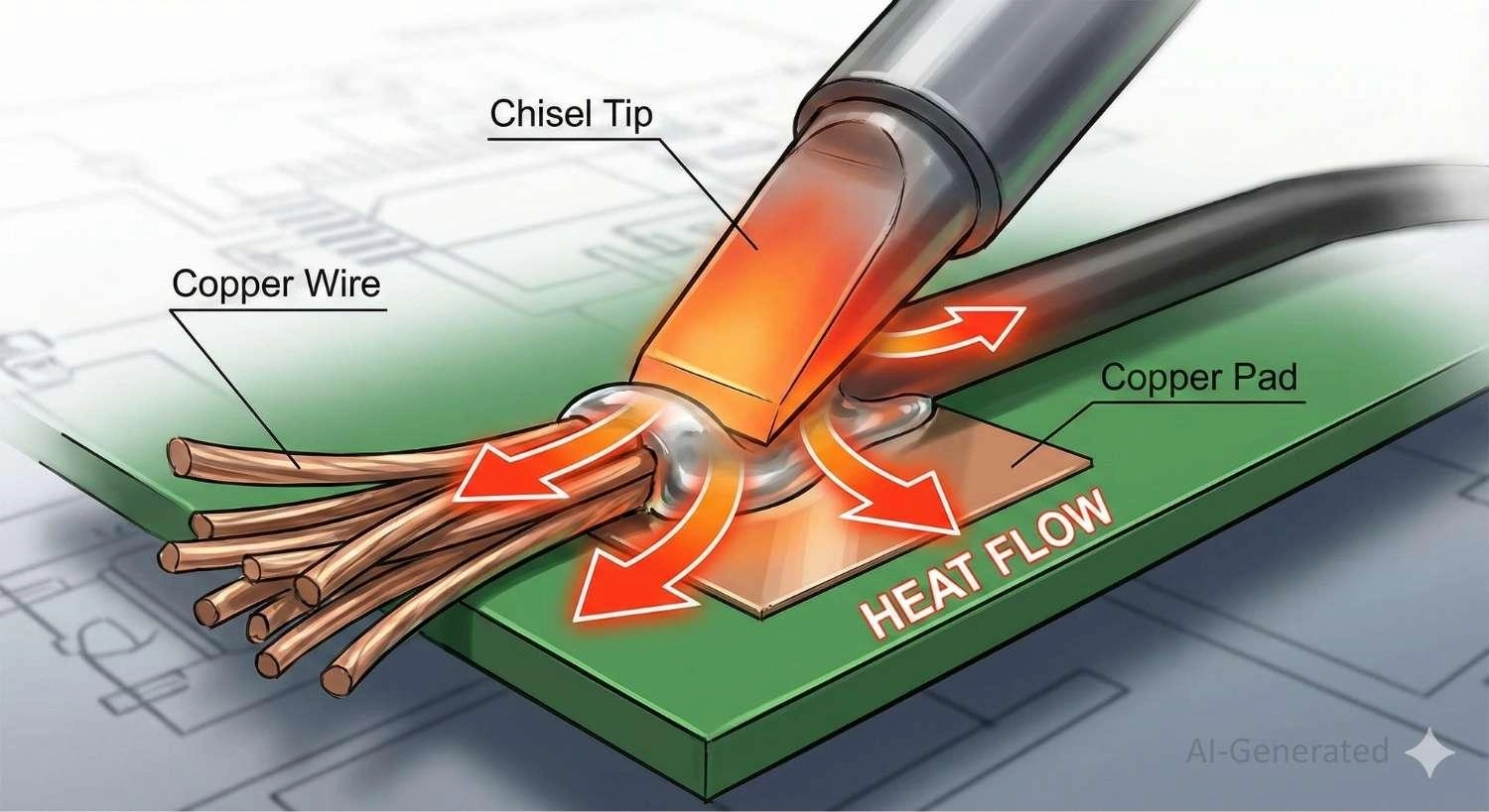
Figure: Illustration of the thermal bridge technique: soldering iron, heating wire, and pad simultaneously.
Step 3 – Feed Solder Into the Joint
- For Through-Hole: A small amount of solder should be fed into the side of the hole that is opposite the iron. The solder will be sucked down into the hole since the melted solder will be heated by the barrel and wire.
- For Surface Mount Pads: You probably do not need extra solder because you have pre-tinned both sides. Just hold the wire in the molten puddle on the pad until you witness the solder from the wire and the pad come together as one fluid mass.
Step 4 – Remove Heat and Hold Still
Remove the soldering iron quickly, but do not move the wire. Keep holding the wire perfectly still and rigid for at least 2 full seconds.
Visual Cue: You will see the shiny liquid surface suddenly turn solid (and slightly duller if using lead-free solder). Wait another second before letting go.
Step 5 – Inspect the Solder Joint
The perfect joint should be like a volcano or a concave tent.
- Through-hole: The solder should completely cover the pad and the wire, and a fillet should be visible on both sides of the board.
- Surface-mount: The wire must be surrounded by the solder instead of lying on a solid ball.
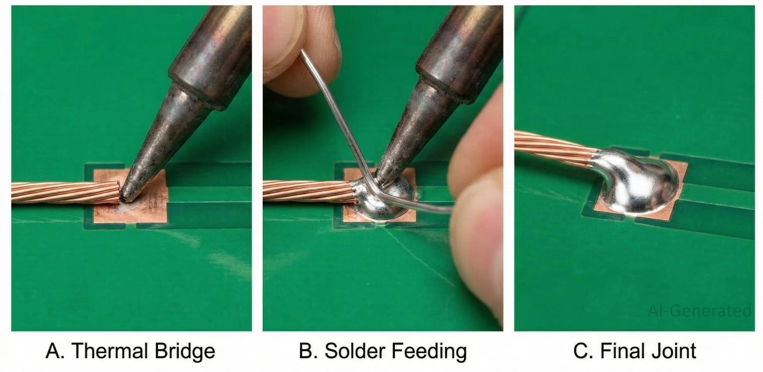
Figure: Soldering a wire to a surface-mount PCB pad
Learn More: PCB Soldering Basic Techniques and Overview
Practical Wire Soldering Tips for Stronger Joints
Beyond the basic steps, adhering to these six engineering rules ensures your connections survive real-world vibration and handling.
- Tin Stranded Wires Properly: Always twist stranded wire tightly before applying solder. Ensure the solder fully wicks into the strands to create a solid core. This prevents individual strands from separating ("birdcaging") and causing short circuits.
- Pre-Tin Both Surfaces: Never skip pre-tinning. Applying a fresh coat of solder to both the wire and the PCB pad separately ensures that the final joining process is fast (under 2 seconds) and relies on reflow rather than heating a cold mass.
- Use Helping Hands: You cannot solder effectively if your hands are shaking or juggling parts. Use a "helping hands" tool or a vise to hold the PCB and wire in a fixed position. Stability is the prerequisite for a good joint.
- Avoid Mechanical Stress During Cooling: If the wire moves even slightly while the solder is transitioning from liquid to solid, the internal crystal structure fractures. This creates a "disturbed joint" that is dull and brittle. Hold the wire rigid until the solder is fully set.
- Use Heat Shrink Tubing: Always slide a piece of heat shrink tubing onto the wire before soldering. Shrinking it over the joint afterward provides excellent electrical insulation and adds mechanical rigidity to the wire entry point.
- Implement Strain Relief: A solder joint should never bear the weight of the wire. Use hot glue, cable ties, or a "service loop" (extra slack in the wire) to anchor the cable to the board. This ensures that any tugging force is absorbed by the strain relief, not the copper pad.
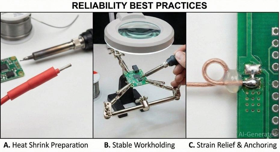
Figure: Best practices for reliable wire soldering: using heat shrink, a helping hands tool, and adding strain relief glue.
Special Tips for Soldering Wires to Surface Mount Pads
The lack of mechanical anchorage during surface soldering makes it very likely to fail. Adhere to these rules to guarantee reliability:
Lay it Flat: Never solder a wire vertically. The high lever arm means a slight nudge can rip the pad off the substrate. Lay the wire flat for 3–5mm to distribute the force.Strain Relief: Once it is cool, apply hot glue or epoxy over the insulated part of the wire to attach it to the FR-4 board. This will pass on the mechanical stress to the board's material instead of the copper foil.Minimal Solder: It is best to avoid making a large "bulb" of solder. The extra solder looks like a cold joint and thus increases the possibility of bridging to nearby components.Common Problems When Soldering Wires to a Circuit Board
Even experienced engineers encounter issues. Understanding the root cause helps you fix them quickly.
Common Soldering Issues | Symptom | Solution |
|---|---|---|
Cold Solder Joints | Dull, grainy, rough surface. | Reheat the joint until both the pad and wire are fully wetted. Apply flux if needed, ensure adequate tip contact, and keep the joint immobile during solidification. |
Non-Wetting | Solder balls up and rolls off. | Clean the pad with IPA, and apply fresh flux. |
Pad Lifting | Copper peels off the board. | Minimize dwell time, avoid repeated rework, and use appropriate tip temperature. Excessive heat or prolonged contact increases the risk of pad lifting, especially on low-Tg boards. |
Birdcaging | Strands splayed out. | Desolder, twist strands tight, pre-tin, and retry |
Insulation Melt | Insulation retracts/exposes wire. | Reduce dwell time; use silicone or PTFE wire. |
Troubleshooting and Rework Tips for Wire Soldering
If you make a mistake, don't panic. Almost everything in hand-soldering PCB work is fixable with patience.
- Reflowing: If a joint looks "dry," add flux and touch with the iron for 1 second to smooth it out.
- Wicking: Use desoldering braid to suck up excess solder if you bridge two pads.
- Scorching: If the board turns brown, your iron is too hot, or dwell time is too long. Clean with IPA.
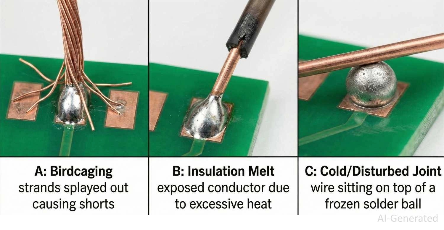
Figure: Common soldering defects: cold joints, solder bridges, and scorched flux.
Inspection Checklist After Soldering Wires to a Circuit Board
Before powering up your device, perform a quick quality control (QC) check. This takes 10 seconds but can save hours of debugging.
- Visual: Is the joint shiny (leaded) or satin smooth (lead-free)? It should not look crinkled.
- Mechanical: Gently nudge the wire with tweezers. Does the wire move inside the solder? (It shouldn't - the whole board should move).
- Clearance: Are there any solder bridges or stray wire strands touching nearby components?
- Insulation: Is the wire insulation okay? If it has melted back quite a bit, then you might have uncovered too much live conductor, thus creating a higher risk of shorts.
Conclusion
The skill of soldering wires to a circuit board is the one that makes it possible to switch between digital design and physical reality. If you are connecting a battery to a development board, fixing a vintage PCB, or altering a prototype, the rules are always the same: cleanliness, heating control, and stability.
Remember, the secret lies in the preparation. If you pre-tin your wires and pads, and use plenty of flux, the solder will do the work for you, naturally flowing into a strong, conductive fillet.
While hand soldering is essential for prototyping, it doesn't scale. Ready to move from prototype to production? Upload your Gerber files to JLCPCB for high-quality PCB fabrication and SMT assembly today. We handle the complex soldering so you can focus on the design.
FAQ
Q: Can I solder wires to a circuit board without holes?
Yes, this is called surface soldering. You must pre-tin both the wire and the flat pad, use flux, and secure the wire mechanically (with glue or tape) after soldering. This prevents the pad from ripping off the substrate due to mechanical stress.
Q: What is the best temperature for soldering wires to a PCB?
The appropriate temperature range is between 320°C and 380°C. Working at 320°C for small signal pads will help you to avoid lifting traces, while 360°C and upwards can be applied for large ground areas or thick power wires that take away heat quickly as they get hot.
Q: Why is my solder balling up and not sticking to the pad?
Generally, this happens because of the oxidation on the pad or wire, or the flux is missing. These oxide layers act as barriers. It is recommended to apply fresh flux, which will chemically break down the oxides, and to use a soldering iron whose tip is clean and tinned.
Q: Do I need to twist the wire strands before soldering?
Yes. Twisting stranded wire prevents "birdcaging" (strands splaying out). If strands separate, they can easily touch adjacent pads, causing dangerous short circuits on the circuit board.
Q: Can I use plumbing solder for electronics?
Absolutely not. Plumbing solder typically contains acid-core flux, which is corrosive and will destroy delicate electronic traces over time. Always use rosin-core or no-clean flux solder meant specifically for electronics.
Q: When and Why Wires Are Soldered to a Circuit Board?
In an ideal Design for Manufacturing (DFM) situation, wires are all replaced by connectors. Nonetheless, direct soldering of wires is frequently required for:
- 1.Power Delivery: Connecting battery packs or power supplies directly to the PCB to minimize voltage drop.
- 2.Signal Jumpers: Soldering "bodge wires" to correct logic or reroute traces during the prototyping phase.
- 3.Temporary Debugging: Attaching logic analyzer grabbers or oscilloscope probes to test points.
- 4.Electromechanical Components: Terminating flying leads from motors, speakers, or limit switches.
Q: Which PCB Pads Are Suitable for Wire Soldering?
The soldering technique depends on the PCB footprint.
Through-Hole Pads
In this robust configuration, the wire passes through a Plated Through-Hole (PTH).
Mechanical Advantage: The solder occupies the barrel and establishes a bond similar to that of rivets. The FR-4 insulating layer absorbs the stress, thus not allowing the wire to tear the joint.
Surface Mount Pads
The usual case is soldering directly onto SMD pads, test points, or ground planes, where the wire is placed right on the copper foil.
The Challenge: Lacking a mechanical anchor, tensile force pulls directly on the copper adhesive, leading to pad delamination.
Key Insight: Successful wire soldering on SMD pads requires controlled heat input to avoid weakening the copper-to-laminate bond, and mandatory strain relief (e.g., epoxy or adhesive) to prevent mechanical stress after cooling.
Popular Articles
• Common PCB Assembly Methods and Soldering Techniques Explained
• What Is BGA Void? Causes, IPC Limits, and Solutions
• SMD Soldering Tools You Need: Complete Guide from Beginner to Pro
• Reflow Soldering: Everything You Need to Know
• SMT Assembly Process Explained and Equipment Used: A Step-by-Step Guide to PCBA Manufacturing
Keep Learning
Common PCB Assembly Methods and Soldering Techniques Explained
Whether you're designing your first prototype or scaling up to production, understanding PCB assembly methods and soldering techniques is crucial to achieving reliable, high-performance circuit boards. Modern PCBA primarily relies on Surface Mount Technology (SMT) and Through-Hole Technology (THT)—each offering unique advantages for component density, durability, and manufacturability. In this guide, we'll break down the major PCB assembly methods, key soldering techniques such as reflow and wave sold......
12 Professional Soldering Tips and Tricks Every Beginner Should Know
Soldering is not merely "gluing" metal; it is a metallurgical process that creates an intermetallic compound (IMC). This molecular bond ensures the electrical and mechanical integrity of your device. A poor joint might pass a quick visual check but will inevitably fail under vibration or thermal stress, leading to "ghost" bugs and hardware failures. These soldering tips and tricks focus on practical, repeatable techniques used in professional electronics soldering—from correct heat transfer and flux u......
Solder Melting Point Guide: Chart, Alloy Types, and Reflow Considerations
In the precise world of electronics manufacturing, a difference of just a few degrees can mean the distinction between a perfect, reliable solder joint and a catastrophic "cold" joint failure. While many hobbyists view soldering simply as "melting metal to stick things together," professional PCB assembly requires a nuanced understanding of thermodynamics. The solder melting point is not simply a single value listed in a datasheet; it is a decisive limit that determines the choice of components, the s......
The Ultimate Guide to Solder Flux: Everything You Should Know Before Soldering PCB
Soldering is needed to make almost all electronic devices. Adding solder alone won't make a joint that is strong, clean, and sound from a metallurgical point of view. Solder flux is a very important part of the process that comes in here. If you want to do your job better and make it more reliable, you need to know a lot about soldering flux, whether you're an engineer, a professional technician, or just a hobbyist. This article goes into a lot of detail about solder flux, including what it is, how it......
Flex PCB Assembly Guide: Process, Challenges, and Solutions
Flexible Printed Circuit Boards (Flex PCBs) are the foundational technology enabling the compact, innovative design of modern electronics. Because of their ability to bend and fold, they power devices from smart wearables to compact medical instruments where traditional rigid printed circuit boards (Rigid PCBs) can't be used. Achieving a functional electronic circuit from the raw plastic film demands special expertise, with flexible PCB assembly (FPCA) representing the crucial final step in this trans......
SMD Rework Guide: Tools, Temperatures, and Techniques That Prevent PCB Damage
From replacing a burned regulator to correcting wrong component values or removing solder bridges on fine-pitch ICs, SMD rework is an essential skill in electronics manufacturing and prototyping. It allows engineers to repair assembly defects, implement design changes, and recover valuable PCBs without the cost and delay of building new boards. In this guide, you will learn: What SMD rework is Common rework scenarios Tools and temperatures Safe removal and installation Package-specific techniques Real......