
12 Professional Soldering Tips and Tricks Every Beginner Should Know
10 min
- Tip 1: Use a Temperature-Controlled Soldering Station
- Tip 2: Set Up a Safe, ESD-Protected Soldering Workstation
- Tip 3: Choose the Right Soldering Iron Tip Shape for Heat Transfer
- Tip 4: Keep the Soldering Iron Tip Properly Tinned at All Times
- Tip 5: Always Heat the Pad and Lead — Not the Solder
- Tip 6: Use Enough Flux To Ensure Wetting, But Avoid Flooding The Board
- Tip 7: Control Dwell Time to Avoid Pad Lifting and Component Damage
- Tip 8: Use the Right Amount of Solder (Fillet Shape Matters)
- Tip 9: Stabilize Small Components Before and During Soldering
- Tip 10: Inspect Every Solder Joint Immediately After Cooling
- Tip 11: Always Perform Final Electrical and Cleaning Checks Before Power-Up
- Tip 12: Practice Makes Better Soldering
- FAQ about Soldering Tips
- Conclusion
Soldering is not merely "gluing" metal; it is a metallurgical process that creates an intermetallic compound (IMC). This molecular bond ensures the electrical and mechanical integrity of your device. A poor joint might pass a quick visual check but will inevitably fail under vibration or thermal stress, leading to "ghost" bugs and hardware failures.
These soldering tips and tricks focus on practical, repeatable techniques used in professional electronics soldering—from correct heat transfer and flux usage to fillet geometry and inspection criteria—so you can consistently produce strong, reliable solder joints on the first pass.
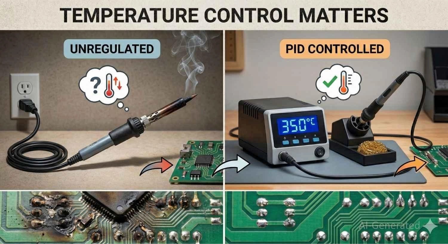
Tip 1: Use a Temperature-Controlled Soldering Station
A common mistake is confusing thermal capacity (wattage) with thermal control. A high-wattage iron without regulation will scorch delicate pads, while a low-wattage iron will "freeze" on ground planes because it cannot recover heat fast enough.
For professional results, look for PID temperature control and rapid thermal recovery (e.g., T12 integrated cartridge tips or induction heating) to maintain stable temps on heavy copper layers.
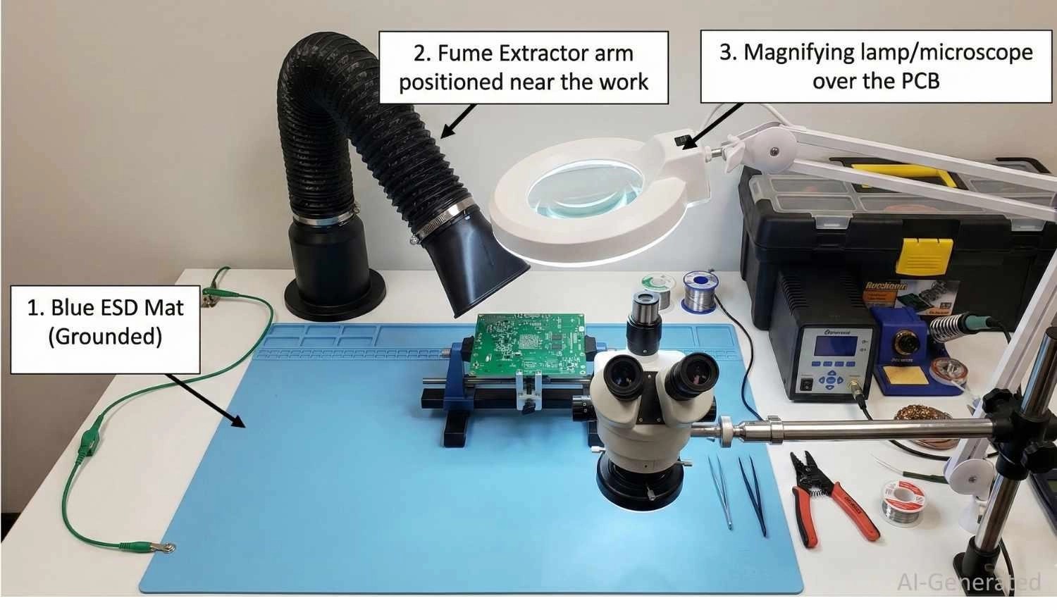
Tip 2: Set Up a Safe, ESD-Protected Soldering Workstation
- Fume Extraction: The "smoke" is not lead vapor, but flux fumes (colophony), which are respiratory sensitizers. Use an activated carbon filter extractor, not just a fan.
- ESD Protection: Modern ICs (MOSFETs/MCUs) are sensitive to static. Use an ESD-safe mat grounded to earth and a wrist strap to drain static voltage.
- Lighting: For 0603 packages or fine-pitch SOIC chips, a 5x-10x stereo microscope or illuminated magnifier is a necessity for verifying wetting angles.
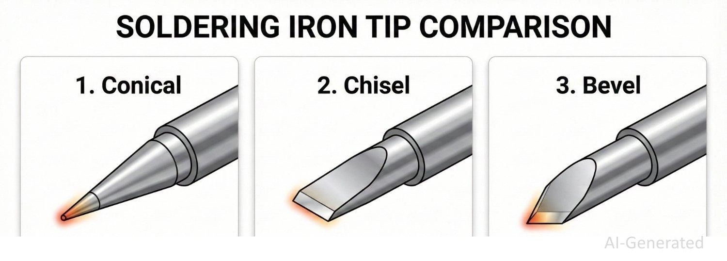
Tip 3: Choose the Right Soldering Iron Tip Shape for Heat Transfer
The soldering iron tip is the interface where thermal energy meets the workload. Its condition and geometry determine 90% of your success.
Stop using the needle-sharp "conical" tip. It has very little thermal mass at the point, making it terrible for heat transfer.
1. Conical (B-Series): Often the default included with irons, but frequently misused. Because the tip comes to a sharp point, it has a minimal contact area, making it poor for heating large pads or ground planes.
Best For: Extremely fine-pitch SMT access or high-density boards where a chisel tip would accidentally touch adjacent components.
2. Chisel (D-Series): The gold standard for 90% of work. The flat face provides excellent surface contact for both the component lead and the PCB pad, transferring heat instantly.
Best For: Through-hole components, wires, and standard SMT pads.
3. Bevel/Knife (K-Series): Holds a bead of solder in its "cup" or face.
Best For: "Drag soldering" multiple pins on a surface mount IC or clearing solder bridges.
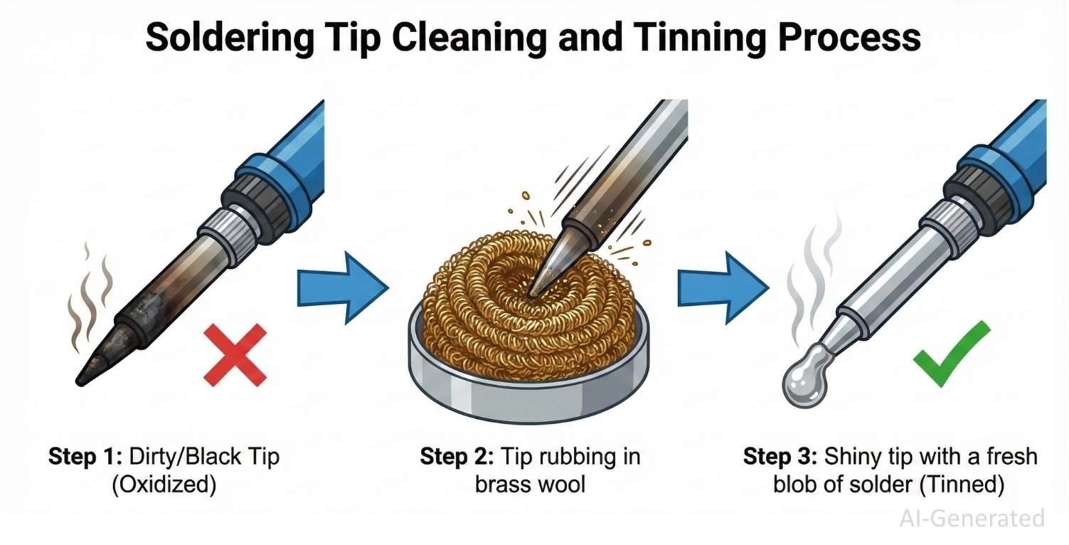
Tip 4: Keep the Soldering Iron Tip Properly Tinned at All Times
If the iron plating oxidizes and turns black, it becomes a thermal insulator. You must maintain a "sacrificial layer" of solder on the tip at all times.
The Golden Rule:
- Clean (Brass wool).
- Solder (The joint).
- Tin (Apply fresh solder to the tip).
- Sleep (Place in holder).
Note
Brass wool is superior to wet sponges. Wet sponges cause thermal shock, cracking the plating and lowering the tip temperature too drastically.
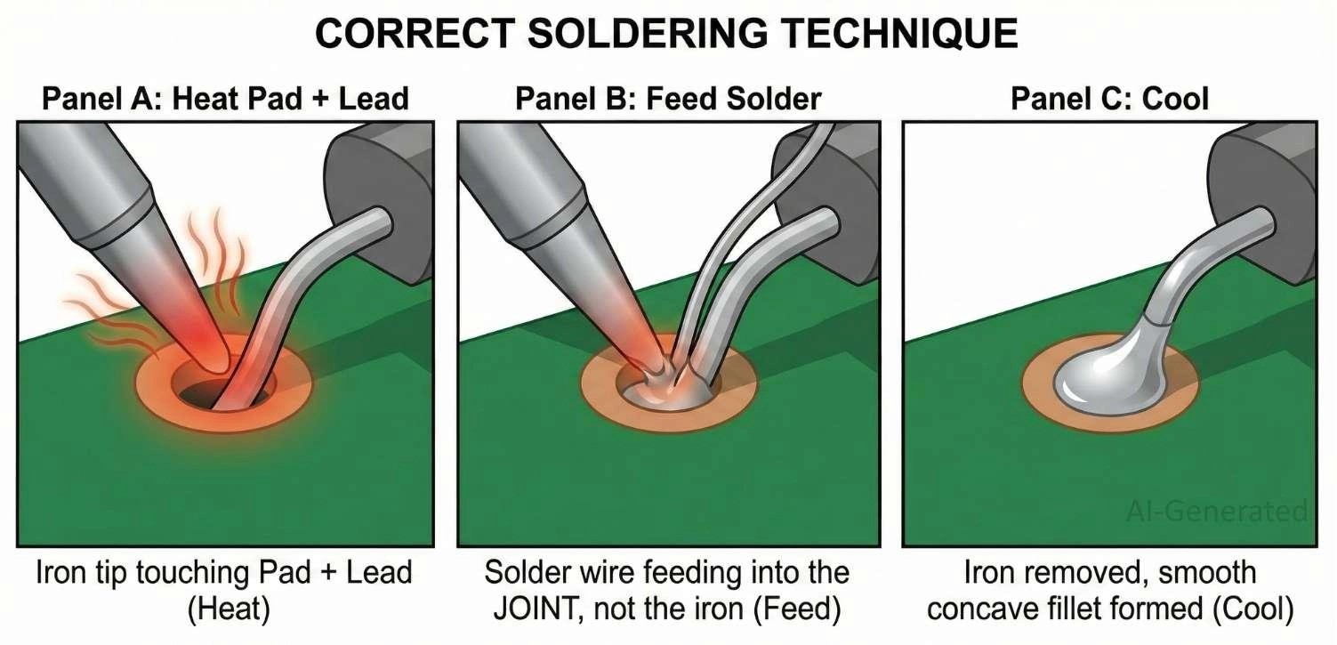
Tip 5: Always Heat the Pad and Lead — Not the Solder
Achieving a perfect joint is about timing. The goal is to heat the target metals enough so they melt the solder, not the iron.
Step 1 — Heat the Joint (The Thermal Bridge):
Dry iron tips transfer heat poorly. Before touching the joint, melt a tiny amount of solder onto the tip to create a thermal bridge. This increases the contact area for instant heat transfer.
Step 2 — Feed Solder to the Heated Area:
Touch the iron to the pad and the lead. Hold for one second. Feed the solder wire into the joint, not the iron tip. If the pad is hot, the solder will wet instantly.
Step 3 — Let Solder Cool Naturally:
Remove the wire, then the iron. Keep the component perfectly still. Movement during the "plastic range" of cooling causes the crystal lattice to fracture, creating a brittle "disturbed joint."
| Step | Action | Technical Reasoning |
|---|---|---|
| Heat | Contact pad & lead | Ensures surfaces reach melting point (183°C–217°C) for intermetallic bonding. |
| Solder | Feed the wire into the joint | Flux core activates on contact, reducing oxides and enabling capillary action. |
| Cool | Remove heat, hold still | Allows alloy to crystallize into a solid structure without micro-cracks. |
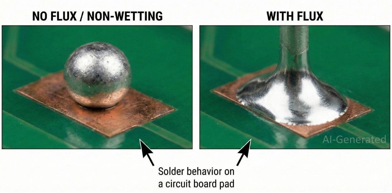
Tip 6: Use Enough Flux To Ensure Wetting, But Avoid Flooding The Board
Flux is essential for reducing surface oxides that prevent wetting. Rosin Activated (RA) flux is more aggressive and effective on oxidized copper, while No-Clean (NC) is the standard for modern assembly.
Apply flux as needed to ensure proper wetting—enough to cover the joint but not flood the board. For solder bridges, clean the iron tip, apply flux, and use solder wick (braid) to remove excess solder.
If the solder balls up, the pad is likely oxidized or contaminated—apply external flux and reheat. (Note: "popcorning" crackling is typically caused by moisture absorption; bake the board/components before soldering if this occurs.)
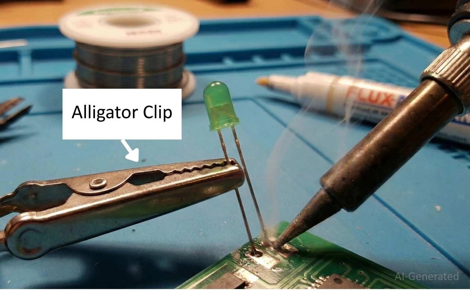
Tip 7: Control Dwell Time to Avoid Pad Lifting and Component Damage
Apply heat efficiently. The ideal dwell time is 2 to 3 seconds. Too long, and you risk pad lifting (delamination of copper from FR4) and component damage.
Use a metal alligator clip on the lead as a heat sink. Keep temp <350°C for sensitive parts.
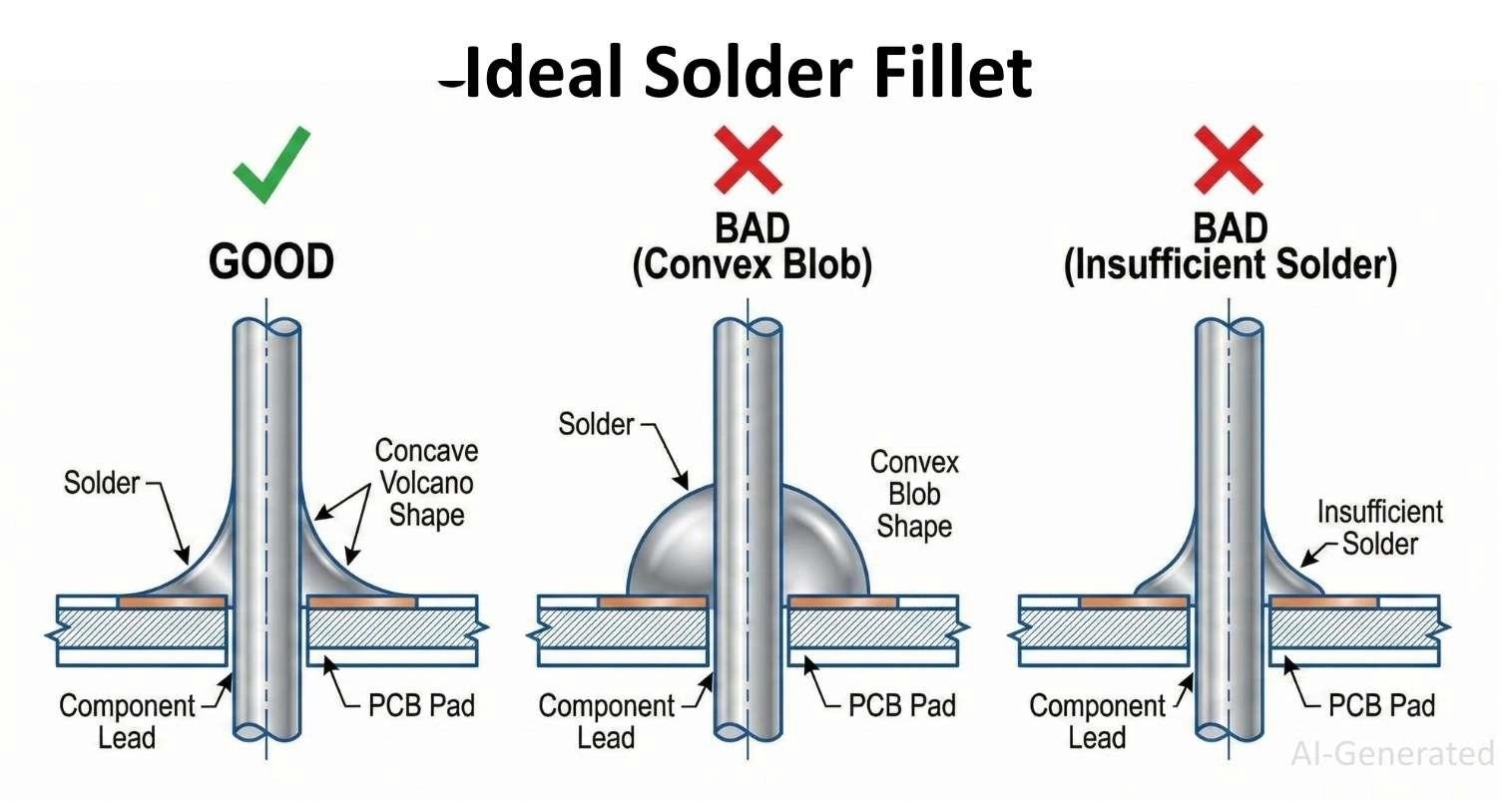
Tip 8: Use the Right Amount of Solder (Fillet Shape Matters)
Use the right amount of solder to form a proper fillet. A perfect joint looks like a concave "volcano." A convex (bulbous) shape indicates non-wetting or hidden voids, which may lead to weak joints or reliability issues.
Tip 9: Stabilize Small Components Before and During Soldering
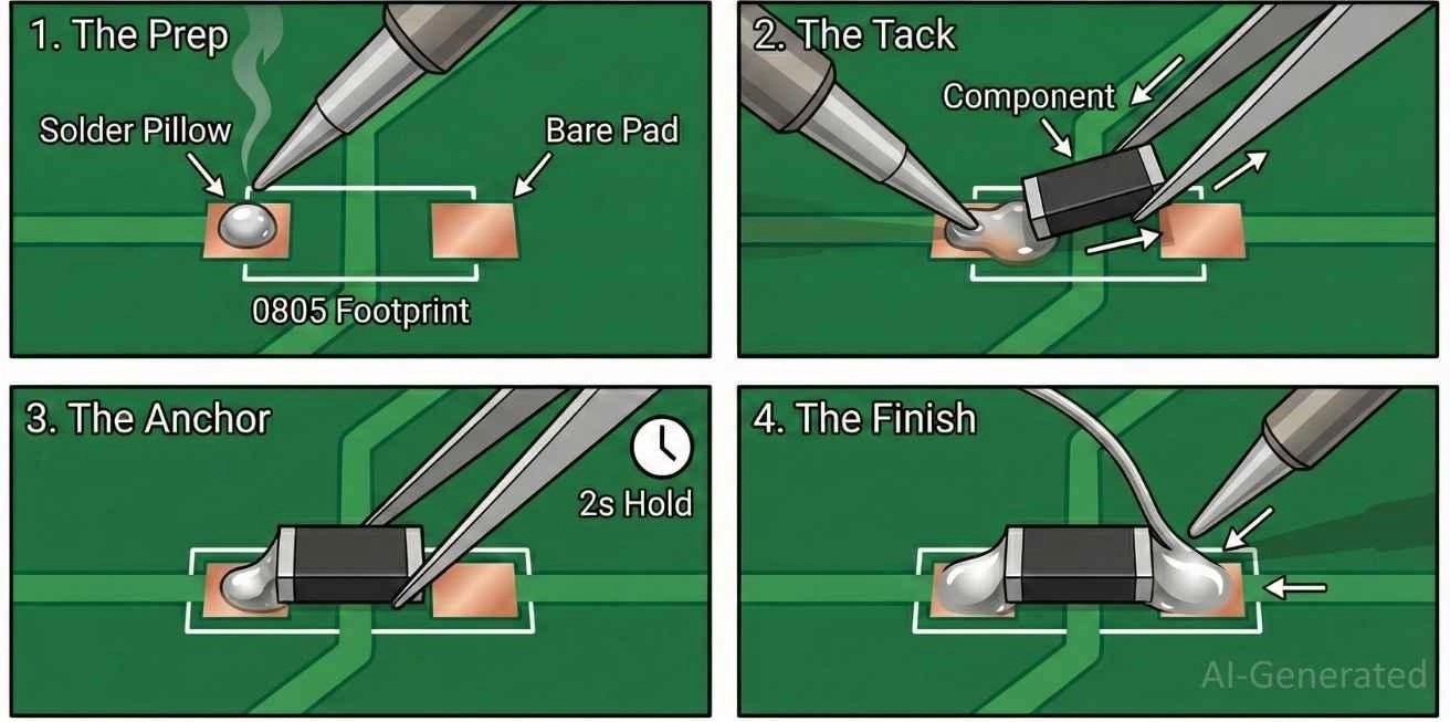
For SMT components, use the tack-and-reflow method to prevent movement.
The tack and reflow soldering method: tinning one pad, sliding the component in with tweezers while heating, anchoring it, and soldering the second pad.
Tip 10: Inspect Every Solder Joint Immediately After Cooling
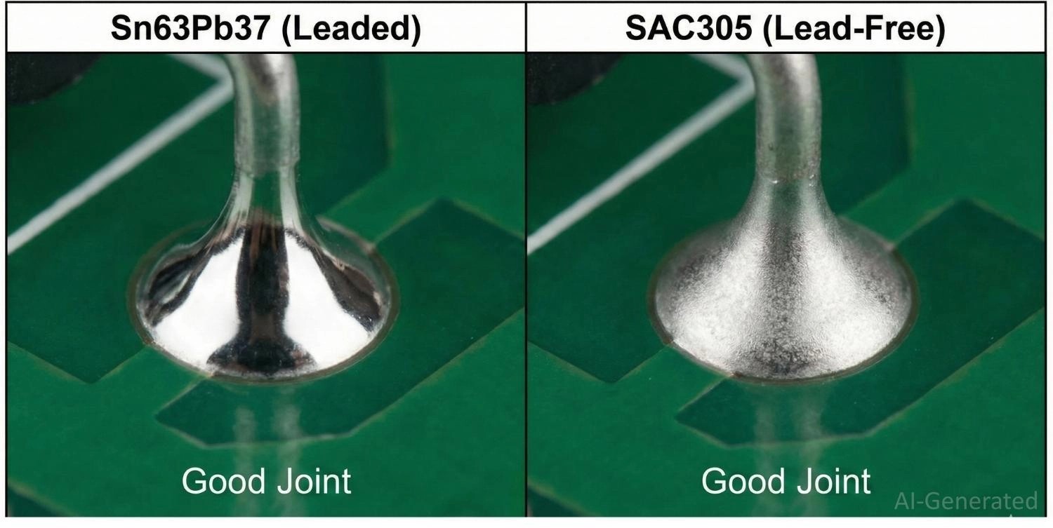
Leaded solder joints are typically bright and shiny, while lead-free joints appear satin or dull but should still be smooth.
A dull appearance alone does not indicate a cold joint — check for proper wetting, a smooth fillet, and absence of cracks, voids, or bridges. Use magnification and continuity testing for critical connections.
To fix the cold joint, you can reflow the joint and ensure the tip makes solid contact with the pad (high thermal mass).
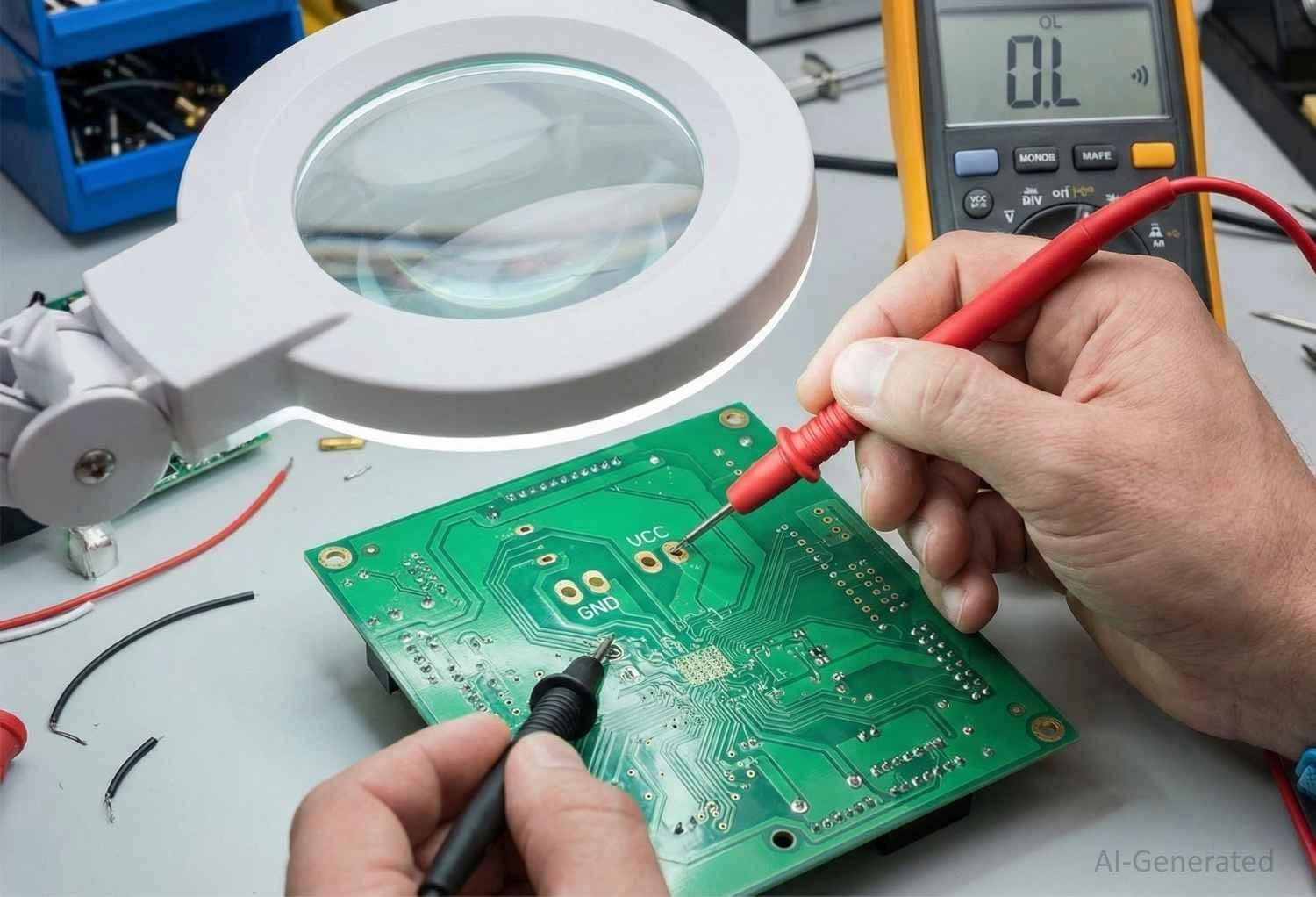
Tip 11: Always Perform Final Electrical and Cleaning Checks Before Power-Up
- Visual Inspection: Lightly tilt the PCB and watch carefully for concealed bridges.
- Continuity Check: Use a multimeter to measure continuity between VCC and GND. A beep indicates that there is a short circuit.
- Cleaning: Remove flux residue with Isopropyl Alcohol (IPA) to prevent long-term corrosion or dendritic growth.
Tip 12: Practice Makes Better Soldering
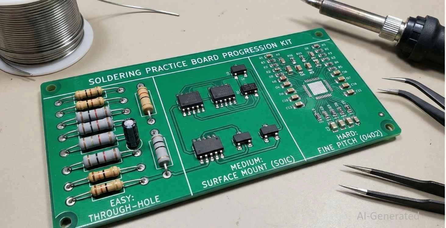
Soldering is a mechanical skill relying on muscle memory. Start with 0.1" headers before moving to 0805 SMT components. However, recognize the limits of hand soldering. It is perfect for prototyping, but inconsistent for volume.
FAQ about Soldering Tips
Q: Why does my solder stick to the iron but not the PCB?
This is a "wetting" failure. The pad is likely oxidized. Clean it and apply an external flux to strip the oxide layer.
Q: Is lead-free solder harder to use?
Yes. It requires higher heat and doesn't flow as easily. The joints also look grainier. Sn63/Pb37 is easier for hobbyist use where RoHS isn't required.
Q: When should I use extra flux?
Whenever wetting is poor, during rework, or when soldering large thermal masses (e.g., ground planes).
Q: What makes soldering difficult for beginners?
The majority of beginners find soldering a tough task since it demands control of heat, time, and hand stability at the same time. Also, a soldering iron, unlike other tools, reacts instantly, so any minor mistake related to positioning or timing can produce a poor joint quality.
Q: How long should a solder joint take to form?
Generally, a good solder joint should be completed in one to three seconds after the heat has been applied. If this process takes much longer, it is mostly due to poor heat transfer or an unfit contact between the iron, pad, and lead.
Q: Can poor soldering cause problems even if the circuit initially functions correctly?
Surely. A circuit could work at first but it might die later due to weak solder joints under the influence of physical vibration, the heat and cold cycles, or the air. A lot of times, the cause of intermittent electronic faults is poor soldering connections.
Q: How much practice is needed to solder reliably?
Basic soldering skills can be easily obtained, but the lack of consistency is usually a result of insufficient practice. Working on non-functional boards is a good way to learn soldering skills without risking damage to the actual circuits that are supposed to be working.
Conclusion
Soldering is not just a step in assembly; it is the heart of hardware reliability. If you accept it as a precise metallurgy rather than a simple mechanical task, you will reduce the risk of latent failures that haunt amateur electronics. With PID-controlled stations, eutectic alloys, and a solid understanding of wetting dynamics, you can manufacture prototypes that are of professional quality.
Nonetheless, even the best hand-soldering technique can hardly keep up with the speed and consistency of an automated assembly line. Thus, when you go from the bench to the market, let JLCPCB's PCB Assembly service do the hard work. Our state-of-the-art SMT capabilities guarantee that the quality you designed is not only replicated in each unit but also done so perfectly and efficiently.
Popular Articles
• Common PCB Assembly Methods and Soldering Techniques Explained
• What Is BGA Void? Causes, IPC Limits, and Solutions
• SMD Soldering Tools You Need: Complete Guide from Beginner to Pro
• Reflow Soldering: Everything You Need to Know
• SMT Assembly Process Explained and Equipment Used: A Step-by-Step Guide to PCBA Manufacturing
Keep Learning
Common PCB Assembly Methods and Soldering Techniques Explained
Whether you're designing your first prototype or scaling up to production, understanding PCB assembly methods and soldering techniques is crucial to achieving reliable, high-performance circuit boards. Modern PCBA primarily relies on Surface Mount Technology (SMT) and Through-Hole Technology (THT)—each offering unique advantages for component density, durability, and manufacturability. In this guide, we'll break down the major PCB assembly methods, key soldering techniques such as reflow and wave sold......
12 Professional Soldering Tips and Tricks Every Beginner Should Know
Soldering is not merely "gluing" metal; it is a metallurgical process that creates an intermetallic compound (IMC). This molecular bond ensures the electrical and mechanical integrity of your device. A poor joint might pass a quick visual check but will inevitably fail under vibration or thermal stress, leading to "ghost" bugs and hardware failures. These soldering tips and tricks focus on practical, repeatable techniques used in professional electronics soldering—from correct heat transfer and flux u......
Solder Melting Point Guide: Chart, Alloy Types, and Reflow Considerations
In the precise world of electronics manufacturing, a difference of just a few degrees can mean the distinction between a perfect, reliable solder joint and a catastrophic "cold" joint failure. While many hobbyists view soldering simply as "melting metal to stick things together," professional PCB assembly requires a nuanced understanding of thermodynamics. The solder melting point is not simply a single value listed in a datasheet; it is a decisive limit that determines the choice of components, the s......
The Ultimate Guide to Solder Flux: Everything You Should Know Before Soldering PCB
Soldering is needed to make almost all electronic devices. Adding solder alone won't make a joint that is strong, clean, and sound from a metallurgical point of view. Solder flux is a very important part of the process that comes in here. If you want to do your job better and make it more reliable, you need to know a lot about soldering flux, whether you're an engineer, a professional technician, or just a hobbyist. This article goes into a lot of detail about solder flux, including what it is, how it......
Flex PCB Assembly Guide: Process, Challenges, and Solutions
Flexible Printed Circuit Boards (Flex PCBs) are the foundational technology enabling the compact, innovative design of modern electronics. Because of their ability to bend and fold, they power devices from smart wearables to compact medical instruments where traditional rigid printed circuit boards (Rigid PCBs) can't be used. Achieving a functional electronic circuit from the raw plastic film demands special expertise, with flexible PCB assembly (FPCA) representing the crucial final step in this trans......
SMD Rework Guide: Tools, Temperatures, and Techniques That Prevent PCB Damage
From replacing a burned regulator to correcting wrong component values or removing solder bridges on fine-pitch ICs, SMD rework is an essential skill in electronics manufacturing and prototyping. It allows engineers to repair assembly defects, implement design changes, and recover valuable PCBs without the cost and delay of building new boards. In this guide, you will learn: What SMD rework is Common rework scenarios Tools and temperatures Safe removal and installation Package-specific techniques Real......