Complete Guide to Resistor Types: Fixed, Variable, and Non-Linear Resistors
21 min
- Resistor Types Chart (Quick Comparison)
- Types of Resistors: Fixed, Variable, and Nonlinear Resistors
- Common Fixed Resistor Types Explained
- Variable Resistor Types: Potentiometers, Rheostats, and Trimmers
- Non-Linear Resistor Types: Thermistors, LDRs, and Varistors
- Special Resistor Types in PCB Design (Arrays, Shunts, and Zero-Ohm)
- How to Choose the Right Resistor Type
- Resistor Types by Application: Which One Should You Choose?
- From Resistor Selection to PCB Assembly
- Conclusion
- FAQs About Resistor Types
The decision becomes difficult even for designers when a circuit board involves different types of resistors. Knowing which one your circuit actually needs solves half of the design problem.
In this guide, you will go through:
- The full resistor types chart — fixed, variable, and non-linear families.
- How to choose between carbon film, metal film, wirewound, and foil resistors.
- When to use a potentiometer, thermistor, LDR, or varistor in design.
- SMD/through-hole resistor types and what each costs you.
- How to choose the right resistor type for your application.
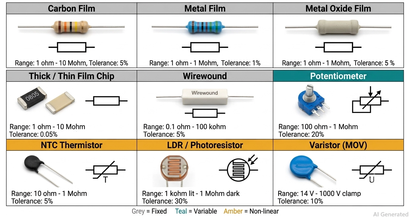
Figure: Resistor types chart showing fixed, variable and non-linear resistor families
Resistor Types Chart (Quick Comparison)
Resistor types fall into three families.
- Fixed resistors hold one value: carbon composition, carbon film, metal film, metal oxide, thick film, thin film, wirewound, and metal foil.
- Variable resistors are adjusted by hand: potentiometers, rheostats, and trimmers.
- Non-linear resistors change value on their own in response to temperature, light, or voltage: thermistors, LDRs, and varistors.
We will see them in detail in the next sections.
| Resistor Type | Family | Tolerance | TCR (ppm/°C Unless Noted) | Typical Range | Power / Rating |
|---|---|---|---|---|---|
| Carbon composition | Fixed | ±5% to ±20% | ±500 to ±1500 | 1 Ω – 22 MΩ | 1/8 W – 2 W |
| Carbon film | Fixed | ±2% to ±5% | −200 to −1000 | 1 Ω – 10 MΩ | 1/8 W – 2 W |
| Metal film | Fixed | ±0.1% to ±1% | ±25 to ±100 | 1 Ω – 1 MΩ | 1/8 W – 1 W |
| Metal oxide film | Fixed | ±1% to ±5% | ±200 to ±350 | 1 Ω – 1 MΩ | 1/2 W – 5 W |
| Thick film (chip) | Fixed | ±1% to ±5% | ±100 to ±200 | 1 Ω – 10 MΩ | 1/16 W – 3 W |
| Thin film (chip) | Fixed | ±0.05% to ±0.5% | ±5 to ±25 | 10 Ω – 1 MΩ | 1/16 W – 1 W |
| Wirewound | Fixed | ±0.005% to ±5% | ±3 to ±50 | 0.1 Ω – 100 kΩ | 1 W – 300 W+ |
| Metal foil | Fixed | ±0.001% to ±0.01% | 0.2 to 2 | 1 Ω – 250 kΩ | 0.1 W – 1 W |
| Resistor array | Fixed | ±1% to ±5% | ±100 to ±200 (±50 tracking) | 10 Ω – 1 MΩ | 1/16 W per element |
| Shunt / metal strip | Fixed | ±0.5% to ±1% | ±20 to ±100 | 0.2 mΩ – 100 mΩ | 0.5 W – 10 W |
| Zero-ohm jumper | Fixed | ≤50 mΩ max | Not applicable | Nominally 0 Ω | Rated by current, 1 A – 2 A |
| Potentiometer | Variable | ±10% to ±20% | ±150 to ±1000 | 100 Ω – 1 MΩ | 0.05 W – 2 W |
| Rheostat | Variable | ±10% | ±20 to ±200 | 1 Ω – 10 kΩ | 3 W – 500 W |
| Trimmer / preset | Variable | ±10% | ±100 to ±250 | 10 Ω – 1 MΩ | 0.1 W – 0.5 W |
| NTC thermistor | Non-linear | ±1% to ±5% | −3 to −5 %/°C (B 3000–4500 K) | 10 Ω – 1 MΩ at 25 °C | 0.1 W – 5 W |
| PTC thermistor | Non-linear | ±25% | Sharp positive step above Curie point | 1 Ω – 1 kΩ | Rated by hold/trip current |
| LDR / photoresistor | Non-linear | ±30% or worse | Resistance falls with illumination | 1 kΩ lit – 1 MΩ dark | 50 mW – 500 mW |
| Varistor (MOV) | Non-linear | ±10% on V1mA | Non-ohmic above clamp voltage | 14 V – 1000 V clamp | Rated by surge energy (J) |
Types of Resistors: Fixed, Variable, and Nonlinear Resistors
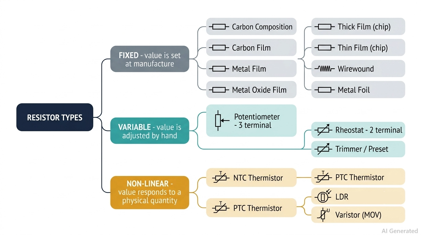
Figure: resistor types classification tree branching from fixed, variable and non-linear resistors
1. Fixed resistors are manufactured to a value and stay there. You judge them on tolerance, temperature coefficient of resistance (TCR), power rating, noise, and long-term drift. Almost every resistor on a finished board is a fixed resistor.
2. Variable resistors expose a movable contact, so with a screwdriver, you can change the value. You judge them on track material, taper, rotational life, and whether the adjustment is meant to happen once or ten thousand times.
3. Non-linear resistors are transducers wearing a resistor's clothes. Their resistance is a deliberate function of an external quantity: temperature for thermistors, illumination for LDRs, and applied voltage for varistors. You judge them on their response curve, not on a tolerance figure.
Schematically, the fixed families all share one symbol, the plain rectangle of IEC 60617 or the zigzag of ANSI/IEEE 315.
But the variable and non-linear types add a modifier: an arrow through the body for a potentiometer, an arrow with a T for a thermistor, arrows pointing inward for an LDR, and a U through the body for a varistor. Recognizing the modifier is how you read a schematic you did not draw.
Resistor Types by Mounting: SMD vs Through-Hole
Mounting style is the second axis, and it cuts across all three families. It is not the same question as package size; it is a question of how the part gets attached to the copper, and therefore how much it costs to assemble.
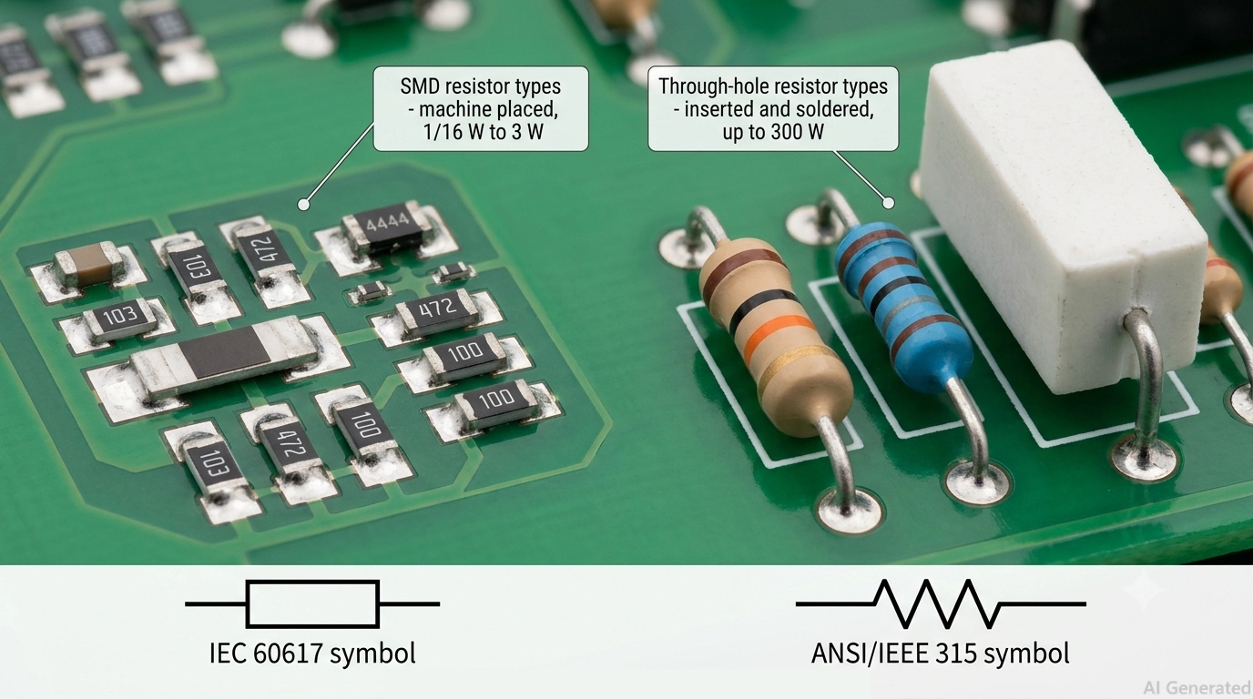
Figure: SMD and through-hole resistors on a populated PCB, showing chip resistors
| Attribute | SMD Resistor Types | Through-Hole Resistor Types |
|---|---|---|
| Families available | Thick film, thin film, MELF, metal strip, arrays, chip NTC, chip varistor, SMD trimmers | Carbon composition, carbon film, metal film, metal oxide, wirewound, foil, pots, LDRs, disc MOVs |
| Typical power | 1/16 W (0402) to 3 W (2512 and power packages) | 1/8 W to 300 W with a heatsink |
| Voltage handling | Limited by body length: 150 V on 0805 unless high-voltage rated | Higher standoff, easier creepage and clearance |
| Assembly method | Machine pick-and-place and reflow | Manual insertion, wave, or selective soldering |
| Relative cost per placement | Lowest | Higher - extra process step, extra labor |
| Board area | Minimal, dense routing is possible | Consumes both sides through the drilled hole |
| Best for | Volume production, compact boards, mixed-signal | Power, high voltage, serviceability, prototyping |
For most designs, the practical answer is "SMD unless there is a reason not to," and the reasons are power, voltage, and human interaction. If you already know you are going surface mount, the complete guide to SMD resistor package sizes covers the footprint side of the decision.
Common Fixed Resistor Types Explained
The seven fixed families below differ in exactly one thing that matters: what the resistive element is made of and how it was deposited. All these resistors can be compared in terms of tolerance, TCR, noise, pulse tolerance and price. Here is each type, what it is genuinely good at, and whether it still belongs in a new design.
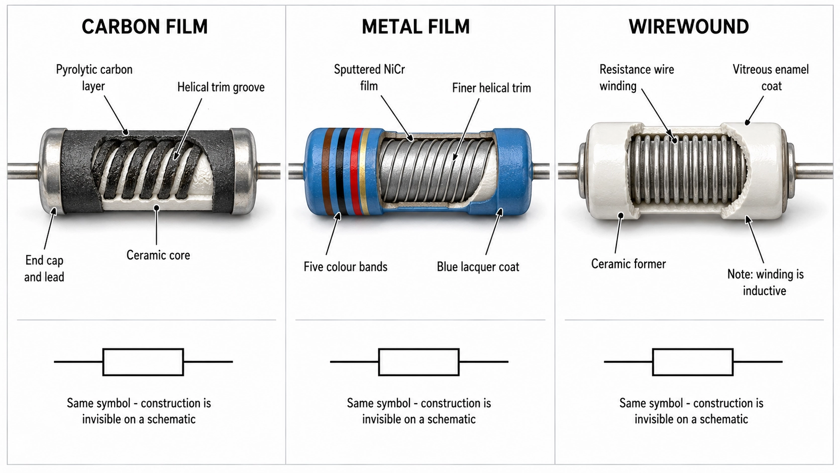
Figure: Comparing carbon film, metal film and wirewound resistor types
Type 1: Carbon Composition Resistors
A carbon composition resistor is a slug of carbon powder mixed with a ceramic binder and molded into a body with the leads at each end. Because the entire volume is resistive, there is no thin surface layer to burn through; that's how they can handle high-energy pulses and surges.
Specs: However, it has poor specs in terms of tolerance of about 5% to 20%, TCR that can reach ±1500 ppm/°C, high current noise, and the value shifts with humidity and aging. Power ratings of carbon composition resistors are from 1/8 W to 2 W.
Verdict: Do not use carbon composition in a new design unless you specifically need its pulse-energy handling. In that case, some applications can be in crowbar circuits, ESD dump paths and high-voltage discharge circuits.
Type 2: Carbon Film Resistors
A carbon film resistor is made by using a hydrocarbon gas onto a hot ceramic rod; in this way, a thin carbon layer deposits on its surface, and then a helical groove is cut into that layer to trim the value up to the target. It is the cheapest through-hole resistor you can buy.
Specs: Carbon film resistors have an expected tolerance of ±2% to ±5%, a strongly negative TCR of −200 to −1000 ppm/°C, and 1/8 W to 2 W ratings across a 1 Ω to 10 MΩ range.
Verdict: They can be used in applications where quantity is required and accuracy is irrelevant. For example: pull-ups, LED current-limiting, bleed resistors, hobby kits, and anything hand-built.
Type 3: Metal Film Resistors
A metal film resistor uses a vacuum-deposited nickel-chromium (NiCr) layer on a ceramic core, then trimmed in the same way as carbon film. The metal layer is homogeneous rather than granular, and that single difference buys tolerance, stability, and quiet.
Specs: Metal film resistors have expected tolerance of ±0.1% to ±1%, TCR of ±25 to ±100 ppm/°C (±50 ppm/°C is the common commercial grade), very low current noise, and good long-term stability. They are available in a power rating of 1/8 W to 1 W, with a practical range of 1 Ω to 1 MΩ.
Verdict: They are a good replacement for carbon film and a default for any through-hole position that affects a measurement. For example: reference dividers, filter networks, amplifier gain-setting, audio signal paths, and instrumentation. However, they are not designed for high-energy surge events.
Type 4: Metal Oxide Film Resistors
A metal oxide film resistor deposits a tin-oxide (SnO₂) layer on a ceramic rod, then coats the body in a flameproof, non-combustible cement. The oxide film tolerates far higher film temperatures than NiCr (several hundred degrees C). So the same body size handles more power and much more pulse energy.
Specs: Tolerance sits at ±1% to ±5% and TCR at ±200 to ±350 ppm/°C, so it is not a precision part. They came with typical power ratings of 1/2 W to 5 W, high operating voltage and excellent surge resistance.
Verdict: They can be a modern replacement for carbon composition in power positions. For example: mains input networks, snubbers, bleeder and discharge resistors, inrush paths, and anywhere a resistor sits close to high voltage.
Type 5: Thick Film and Thin Film Resistors
Thick film and thin film are the two chip-resistor families you will actually place on a modern board, and together they cover almost every surface-mount position. Thick film uses a resistive paste fired onto ceramic; it is cheap, tough under surge, and the default for pull-ups, LED current-setting, and general digital work.
Thin film uses a much thinner sputtered metal alloy that is laser-trimmed to value. It buys a tighter tolerance, roughly ten times lower temperature drift, and lower noise, at several times the price. For the full comparison, see our guide to thick film vs thin film resistors.
Verdict: Use thin film where precision is required, and a resistor sets an analog quantity (a divider ratio, a reference, an amplifier gain, a sense signal). Everything else gets thick film.
Type 6: Wirewound Resistors
A wirewound resistor is exactly what it sounds like, a length of resistance wire (made of nichrome for power grades, Manganin or Evanohm for precision) wound onto a ceramic or fiberglass core. And then sealed under silicone or an aluminum housing.
There are two types of wirewound resistors available:
- Power wirewound handles 1 W to well over 300 W in a chassis-mount aluminum-clad body, absorbs enormous pulse energy, and survives thermal abuse that would vaporize a film part.
- Precision wirewound reaches ±0.005% tolerance with TCR down to ±3 ppm/°C in low-value ranges no film technology can match.
But a coil is a coil that brings inductance into the equation. And a standard wirewound is usable up to a few tens of kilohertz and starts oscillations at a higher frequency. So it is not suitable for RF-grade circuits.
Verdict: They found applications where we required higher power dissipation, pulse energy, or low-value precision. For example: dummy loads, braking resistors, motor and heater circuits, current shunts.
Type 7: Metal Foil Resistors
A metal foil resistor starts as a bulk nickel-chromium alloy foil, cold-rolled and cemented to a ceramic substrate, then photo-etched into a precise pattern. The substrate is chosen so that its thermal expansion mechanically cancels the foil's natural resistance change with temperature.
Specs: They came with a tolerance ±0.001%, a TCR of 0.2 to 2 ppm/°C, long-term drift measured in single-digit ppm per year, negligible inductance and capacitance, and thermal settling in under a second.
Verdict: They are used in metrology and calibration standards, precision instrumentation, medical and aerospace references, and ATE. They came with a higher price tag because of their reliability.
Note
Whichever family you land on, you still have to read the value off the finished part — through-hole types use color bands, chip types use printed numeric codes, which our SMD resistor code guide and SMD resistor value guide decode in full.
Variable Resistor Types: Potentiometers, Rheostats, and Trimmers
A variable resistor uses a resistive element and a movable contact called a wiper. Different configurations, materials, and adjustment mechanisms determine whether it is used as a potentiometer, rheostat, or trimmer.
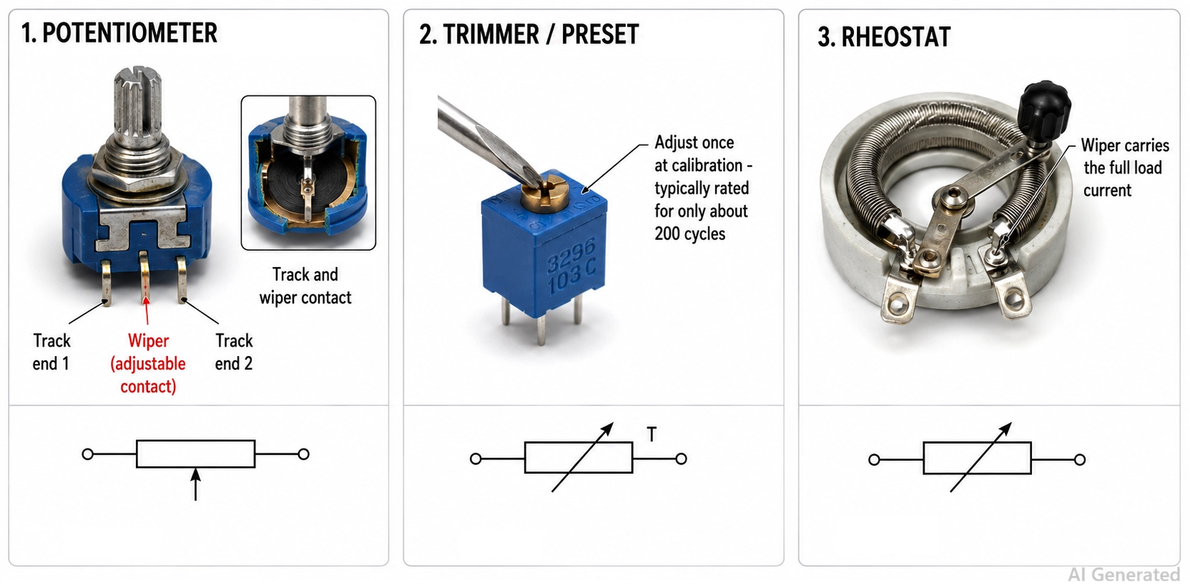
Figure 5: variable resistor types showing a rotary potentiometer, a cermet trimmer and a wirewound rheostat
Type 1: Potentiometer
A potentiometer brings out all three terminals: both ends of the track plus the wiper. Wired that way, it is a voltage divider, and the output voltage at the wiper follows the shaft position. Potentiometers are widely used in volume controls, setpoint dials, and joystick axes, because the wiper carries almost no current and wiper resistance barely matters.
Type 2: Rheostat
A rheostat is the same physical part, using only two terminals. One end of the resistive track and the wiper are used as the two terminals. So it becomes a variable resistance in series with the load.
Now the wiper carries the full load current, contact resistance shows up directly in the result, and the part's power rating becomes a real constraint. You can find them in any electronics/electrical lab, because they are widely used variable resistors in experimental setups.
Type 3: Trimmer
A trimmer (or preset) is a small board-mounted potentiometer adjusted once with a screwdriver at calibration and then left alone. Single-turn trimmers give you coarse adjustment; 25-turn cermet trimmers give you the resolution to null an offset properly.
Track material sets the quality: Carbon tracks are cheap and noisy with ±20% tolerance; cermet tracks are stable and the standard for trimmers.
The specification competitors omit is rotational life. A panel potentiometer is rated for 10,000 to 1,000,000 cycles. A trimmer is often rated for 200 cycles. Put a trimmer where less activity is required, for example, instrument internal calibration.
Non-Linear Resistor Types: Thermistors, LDRs, and Varistors
Non-linear resistors are the least-documented corner of the resistor family and the one that causes the most field failures, because designers treat them as components with a value rather than as devices with a characteristic curve.
| Non-Linear Type | Resistance Behaviour | Key Specification | Typical Use |
|---|---|---|---|
| NTC thermistor | Falls as temperature rises | R25 and beta value (K) | Temperature sensing, inrush current limiting |
| PTC thermistor (switching) | Jumps sharply above the Curie point | Switch temperature, hold current | Resettable overcurrent protection, self-regulating heaters |
| PTC silistor | Rises gently and near-linearly | TCR in %/°C | Temperature compensation and sensing |
| LDR / photoresistor | Falls as illumination rises | Dark and 10 lux resistance, response time | Dusk switching, legacy light sensing |
| Varistor (MOV) | Collapses above the varistor voltage | V1mA, clamping voltage, energy in joules | Mains and I/O surge suppression |
Type 1: NTC Thermistor
An NTC thermistor is a sintered metal-oxide bead whose resistance falls sharply as it heats. It can be used as a sensor or as an inrush current limiter.
- As a sensor, the 10 kΩ-at-25 °C NTC is the industry standard, characterized by its beta value (typically 3000–4500 K) and read through a divider.
- As an inrush limiter, a large power NTC sits in series with a supply input and its resistance limits the capacitor charging surge at power-on; once current flows, self-heating drops it to a fraction of an ohm, so it stops wasting power.
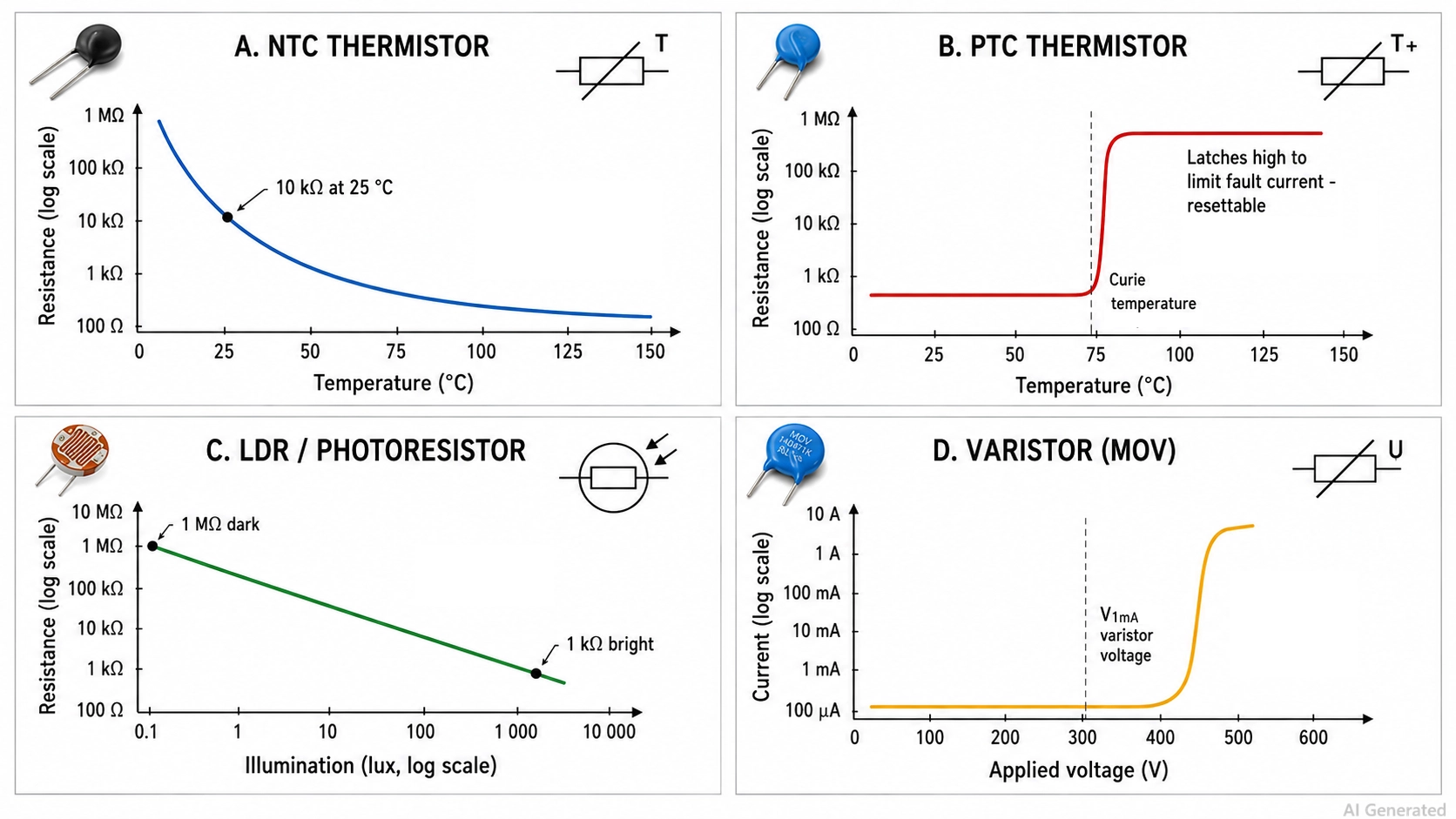
Figure: response curves for non-linear resistor types comparing NTC thermistor, PTC thermistor, LDR, and varistor
Type 2: PTC Thermistor
A PTC thermistor does the opposite of an NTC. A switching PTC, built from doped barium titanate, holds a low resistance until it reaches its Curie point, then increases resistance by orders of magnitude within a few degrees. It is used as a resettable fuse and latches the fault current down to a trickle, then recovers when power is removed and it cools.
Type 3: LDR
An LDR (photoresistor) uses a cadmium-sulfide film whose resistance drops from around 1 MΩ in darkness to a few kilohms in bright light. The response is slow, taking from tens to hundreds of milliseconds. Cadmium is RoHS-restricted, so new designs should use a phototransistor or ambient-light IC. Still, LDRs are mainly used in nightlights, dusk switches, and legacy equipment.
Type 4: Varistor
A varistor, almost always a metal-oxide varistor (MOV), is a zinc-oxide ceramic that behaves as an insulator below its varistor voltage and collapses to a low impedance above it. It is used for clamping transients. Specify it by V1mA, clamping voltage, energy rating in joules, and peak surge current for an 8/20 µs pulse.
An MOV degrades with every surge it absorbs and eventually fails short, which is why mains designs use a thermally protected MOV or put a fuse upstream.
Special Resistor Types in PCB Design (Arrays, Shunts, and Zero-Ohm)
Four more resistor types exist purely because of how boards are built, and each one solves a layout or manufacturing problem rather than an electrical one.
Type 1: Resistor arrays and networks
Resistor arrays put four or eight elements in one body; four 0402 elements inside a 1206-size package is a common convention. You save three placements and a lot of board area on a pull-up bank or a bus termination.
The real advantage is subtler: the elements are printed and trimmed together, so their ratio tolerance (often ±0.05%) and tracking TCR (often ±5 ppm/°C) are far better than their absolute tolerance. That makes arrays excellent for matched dividers even when the absolute value is loose.
Type 2: Current-sense shunts
The current-sense shunts are solid metal-element resistors from about 0.2 mΩ to 100 mΩ, built from Manganin or Zeranin alloy for a TCR near zero.
Above roughly 10 A, use a four-terminal (Kelvin) shunt: the two heavy pads carry the load current and two separate sense pads tap the element itself, so solder joint and trace resistance never enter the measurement. A two-terminal shunt at high current measures your layout as much as your load.
Type 3: Zero-ohm resistors
The zero-ohm resistors are linked in a resistor footprint, marked "000" or "0" and specified by maximum resistance (typically ≤50 mΩ) and maximum current, not by value. They let you cross-trace on a single-layer board and give you populate/depopulate options to configure different signal/power paths on a PCB.

Once you have selected the right resistor type, the next step is bringing your design into production.
JLCPCB offers PCB fabrication and assembly services with component sourcing and SMT placement. Upload your Gerber files and BOM for an instant quote.
How to Choose the Right Resistor Type
Work these five filters in order. Each one removes families from the running, so by step five, you are usually choosing between two parts, not twenty.
- Fix the value and tolerance first.
- See the maximum power rating of the supply.
- Check stability: TCR, noise, and long-term drift.
- Match the environment and mounting.
- Confirm availability and cost before you commit.
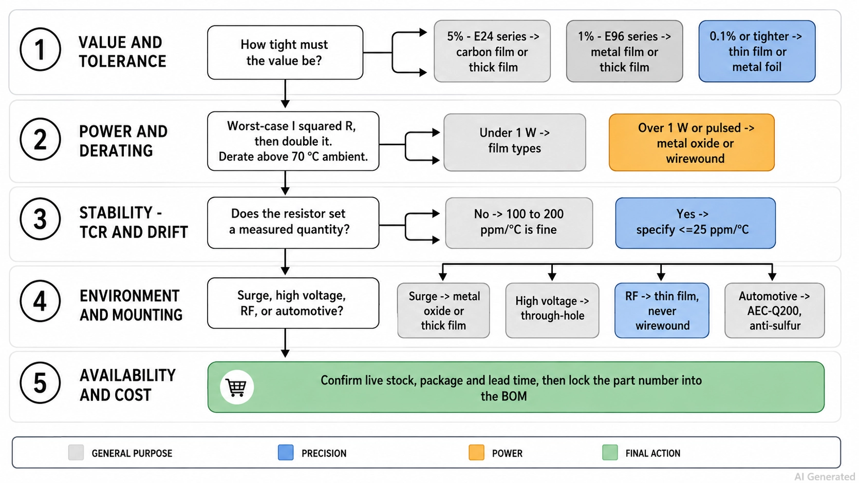
Figure: resistor type selection flowchart
Resistor Types by Application: Which One Should You Choose?
| Application | Recommended Resistor Type | Tolerance | Why |
|---|---|---|---|
| Pull-up/pull-down | Thick film chip | ±5% | Logic only needs a threshold, not a value |
| LED current-limiting | Thick film or carbon film | ±5% | A few percent of brightness change is invisible |
| Feedback divider on a regulator | Thin film or metal film | ±0.1% to ±0.5% | The ratio sets the output voltage over temperature |
| ADC front-end divider | Thin-film chip | ±0.1% | Drift converts directly into lost LSBs |
| Voltage reference network | Metal foil or thin film | ±0.01% to ±0.1% | Reference accuracy cannot exceed the resistors |
| Amplifier gain-setting | Thin film matched pair or array | ±0.1% | Ratio tracking matters more than absolute value |
| High-current sensing | Metal strip shunt (4-terminal) | ±0.5% to ±1% | Kelvin sensing removes trace and joint resistance |
| Inrush current limiting | Power NTC thermistor | ±20% | Cold resistance limits the surge, then self-heats away |
| Mains surge protection | Varistor (MOV), thermally protected | ±10% on V1mA | Clamps transients; must fail safe |
| Snubber and bleeder networks | Metal oxide film | ±5% | High voltage and pulse energy, safe failure mode |
| Dummy load or braking resistor | Power wirewound | ±5% | Dissipates tens of watts continuously |
| User volume or setpoint control | Potentiometer (conductive plastic) | ±20% | Rated for long rotational life and low noise |
| One-time board calibration | Multi-turn cermet trimmer | ±10% | Fine resolution, set once and left alone |
| RF matching and termination | Thin-film chip | ±1% | Low parasitics keep the response flat |
From Resistor Selection to PCB Assembly
Many resistor types covered in this guide are available in surface-mount packages designed for automated pick-and-place assembly.
Standard thick film chip resistors in common values are available as basic parts, helping simplify sourcing and reduce assembly complexity. For many general-purpose PCB designs, thick film resistors are a practical default choice.
Thin film, tight-tolerance, shunt, and resistor array parts may require additional availability checks before finalizing your BOM. The practical workflow is to filter the JLCPCB Parts Library by resistance, tolerance, TCR, package, and part category, verify availability, and add the selected part numbers directly to your BOM.
Once your BOM is finalized, upload your Gerber files, BOM, and placement files through the JLCPCB quote flow to combine PCB fabrication, component sourcing, and assembly in a single order.
Get Quote Now >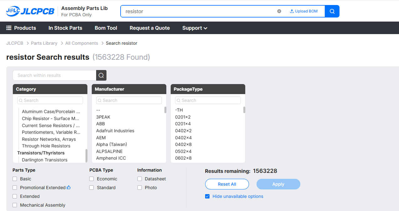
Conclusion
Choosing the right resistor type depends on your circuit requirements, including accuracy, power handling, stability, and adjustment needs. Understanding the differences between fixed, variable, and non-linear resistive components helps you select reliable components for each application.
Avoid the common mistakes in resistor selection:
- Putting a carbon film in a precision divider.
- Ignoring the pulse rating on wirewound and film parts.
- Sizing a resistor at its rated power without an extra derating margin.
- Using a trimmer where a potentiometer belongs.
Once you have selected the right components, you can source verified parts through the JLCPCB Parts Library and move your design from schematic to assembled PCB through the PCBA service.
FAQs About Resistor Types
Q: What are the main types of resistors?
The main resistor types are fixed, variable, and non-linear. Fixed resistors include carbon composition, carbon film, metal film, metal oxide film, thick film, thin film, wirewound, and metal foil. Variable resistors include potentiometers, rheostats, and trimmers. Non-linear resistors include NTC and PTC thermistors, LDRs, and varistors.
Q: What is the difference between fixed and variable resistors?
A fixed resistor is manufactured to one value and stays there for its life; you select it by tolerance, TCR, and power rating. A variable resistor has a resistive track and a movable wiper, so its value can be changed after assembly — by a user turning a knob on a potentiometer, or by a technician adjusting a trimmer once at calibration.
Q: Which type of resistor is the most accurate?
Metal foil resistors are the most accurate resistor type available, reaching ±0.001% tolerance with a TCR of 0.2 to 2 ppm/°C and drift of only a few ppm per year. They are used in metrology, calibration standards, and precision instrumentation. For accurate parts at sane prices, precision thin film at ±0.05% and 5 ppm/°C is the practical choice.
Q: Which resistor type can handle the most power?
Wirewound resistors handle the most power. Vitreous-enamel and aluminum-clad chassis-mount wirewounds are rated from a few watts to over 300 W when heatsinked, and they absorb very high pulse energy. Their drawback is series inductance, so keep them out of RF and fast-edge signal paths; metal oxide film covers the 1 W to 5 W range on a board.
Q: Which resistor type should I use on a PCB?
On a modern PCB, default to thick film chip resistors for pull-ups, LED current-setting, and general digital positions, and switch to thin film wherever a resistor sets an analog quantity. Add metal strip shunts for current sensing, arrays for pull-up banks, metal oxide for high-voltage or snubber positions, and wirewound for real power dissipation.
Popular Articles
• SMD Resistor Package Sizes: Complete Size Chart, Footprints & How to Choose
• How to Solder SMD Components Like a Pro [2026 Updated]
• SMD Resistor Codes: How to Read 3-Digit, 4-Digit, and EIA-96 Markings
• SMD Capacitor Codes: Identification, Markings, and Polarity
• SMD Capacitor Sizes: Complete Size Chart and Selection Tips for PCB Design and Assembly
Keep Learning
SMD MOSFET Code Guide: How to Identify, Test and Replace a MOSFET
Figure: AO3400A (C20917) in the JLCPCB parts library. The listing gives RDS(on) at 2.5 V gate drive, the number that matters in the replacement example later in this guide. An SMD MOSFET code is the two or three characters printed on top of the package, and on its own it rarely tells you which part you're holding. SMD resistors follow standard marking schemes, such as three- and four-digit codes and EIA-96. MOSFETs don't. The same short code can appear on unrelated parts from different manufacturers, ......
ESP8266 vs ESP32: Which One Should You Use?
Key Takeaways ESP32: Dual-core 240 MHz CPU, Bluetooth Classic and BLE, 520 KB SRAM, and up to 34 GPIOs. ESP8266: Single-core CPU, no Bluetooth, and around 50 KB of free RAM for applications. Lifecycle status: Espressif marks the ESP8266 Not Recommended for New Designs (NRND) and names the ESP32-C2 (ESP8684) as its upgrade, although the ESP8266 remains in production with a longevity commitment. Which ESP32 to use: Choose the ESP32-C2 for simple Wi-Fi or Bluetooth LE firmware, the ESP32-C3 for more memo......
What Is a Thermistor? A Practical Guide to NTC, PTC, Applications, and Circuit Design
Key Takeaways Definition: A thermistor is a thermally sensitive resistor whose resistance changes markedly and predictably with temperature, typically by about 4.4% per °C for a standard 10 kΩ NTC (B25/50 = 3950 K) near 25 °C. NTC vs. PTC: An NTC thermistor's resistance falls as temperature rises, which suits temperature sensing and inrush current limiting; a switching PTC's resistance rises steeply above its switch temperature, which suits circuit protection. Key Specifications: An NTC thermistor is ......
What Is the ESP32-CAM, and How to Wire, Power, and Program It?
Key Takeaways Board, not chip: The ESP32-CAM is an AI-Thinker development board, not an Espressif product. It carries AI-Thinker's ESP32-S module, an OV2640 camera, PSRAM, a microSD slot, and a flash LED. No USB port: The board has no USB connector or USB-to-UART bridge, so you program it via its serial pins using a 3.3 V USB-to-serial adapter, with GPIO0 held low at reset. Few free pins: The camera, PSRAM, and microSD card occupy most GPIOs. With the microSD card unused, GPIO2, GPIO4, GPIO12, GPIO13,......
ESP32 Versions: Which One Should You Use for Your Project?
Key Takeaways Radios decide first: ESP32 versions differ mainly in their radios, CPU cores, and peripherals. Common defaults: The ESP32-C3 suits low-cost Wi-Fi and Bluetooth LE, the ESP32-S3 suits camera, display, voice, and on-device AI. Original ESP32: The chip is still in production and remains the choice for Bluetooth Classic. Versions without Wi-Fi: The ESP32-H2 targets battery-powered Thread and Zigbee devices. Chip, module, or board: Prototype on a development board, then design a module onto y......
SOIC Package: A Complete Guide to Specifications, Types, Uses, and SMT Assembly
As designs transition from legacy through-hole components to high-density Surface Mount Technology (SMT), the Small Outline Integrated Circuit (SOIC) remains the industry standard for operational amplifiers, flash memory, sensors, and microcontrollers. It reflects a well-balanced engineering design, offering a practical compromise between the miniaturisation demanded by modern consumer electronics and the ruggedness required for industrial applications. In this guide, you will learn: SOIC package dime......