
Why Choosing the Right TG Value Leads to More Reliable PCBs
11 min
- Understanding Tg Value in PCB Materials
- How Tg Value Affects PCB Performance and Reliability
- Selecting the Optimal Tg Value for Your Application
- Manufacturing Considerations for High Tg Value PCBs
- JLCPCB's Expertise in High Tg Value PCB Production
- FAQ about PCB Tg Value
- Conclusion
Key Takeaways
- Tg is key to PCB reliability — it determines when the material loses rigidity under heat.
- Choose high Tg (≥170°C) for automotive, industrial, or multilayer boards to reduce expansion stress and delamination.
- Standard Tg (130–140°C) is sufficient for low-power consumer electronics.
- Higher Tg delivers better thermal stability, especially during lead-free soldering and thermal cycling.
- Right Tg choice = fewer failures and lower long-term costs.
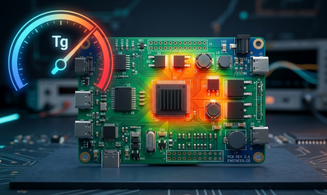
Did you ever question how it's possible for 2 boards made from "the same" FR4 to act so differently when the heat is turned up? Many times, it's the number that appears in silence on the datasheet: the Tg Value. One of those specs that the beginner does not consider and the experienced engineer does not overlook. Your PCB doesn't break at room temperature. It fails when reflowing, on a hot summer afternoon in a car, or after 1,000 power cycles in an industrial drive.
In all of these instances, your laminate's glass transition temperature is silently determining the board's survival or fracture. Today, we will be delving into the meaning behind the Tg Value, how to measure it, and how to choose the correct one for your application. We'll also examine the manufacturing side, as selecting a high Tg is one thing, and manufacturing it the right way is another.
Understanding Tg Value in PCB Materials
What Tg Value Means and How It Is Measured
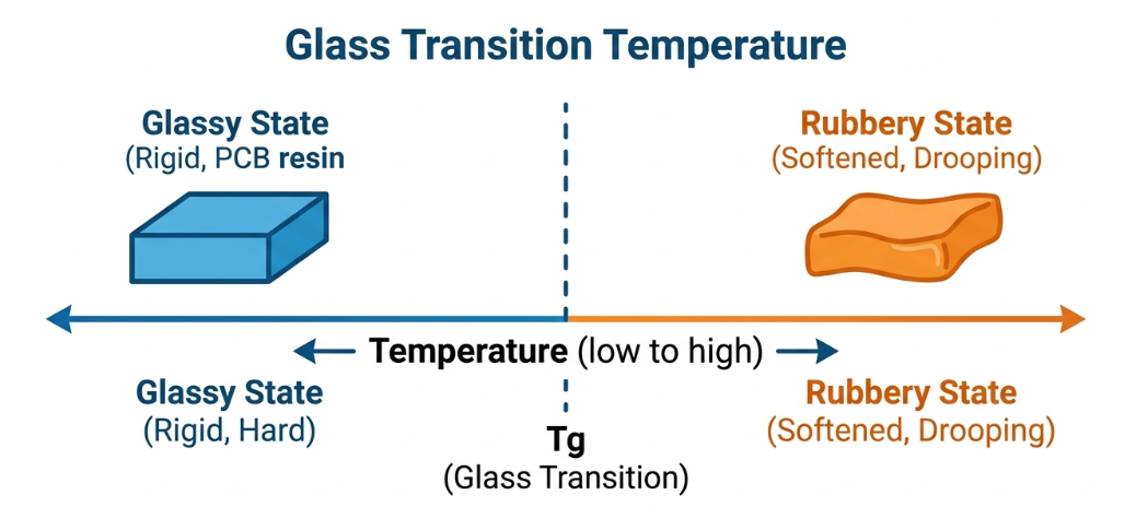
What then is the value of Tg in PCB terms? Glass Transition Temperature (Tg) is the temperature at which the resin in your laminate moves from a hard glassy state to a soft, rubbery state. At temperatures below Tg, the board acts like a hard, stable solid. The resin softens, and expansion increases above Tg, and the temporary loss of much of the mechanical strength of the resin occurs. The word is transition, not destruction. To reverse Tg, simply cool the board back down, and the resin becomes glassy once again, with most properties intact. This differentiates it from the decomposition temperature (Td), which represents the temperature at which 5% of the mass of the material is lost due to chemical decomposition. Tg is determined by three standard thermal analysis techniques, all according to IPC-TM-650:
- DSC (Differential Scanning Calorimetry): senses the change in heat capacity that occurs when the resin changes.
- TMA (Thermomechanical Analysis): measures the point where Z-axis dimensional expansion suddenly accelerates.
- DMA (Dynamic Mechanical Analysis): measures the decrease in mechanical stiffness of the resin as it softens.
The Tg of the same laminate might be slightly different depending on the test because each method measures a slightly different physical change. Before comparing two materials head-to-head, always take note of which method a datasheet is using.
Difference Between Standard and High Tg Materials
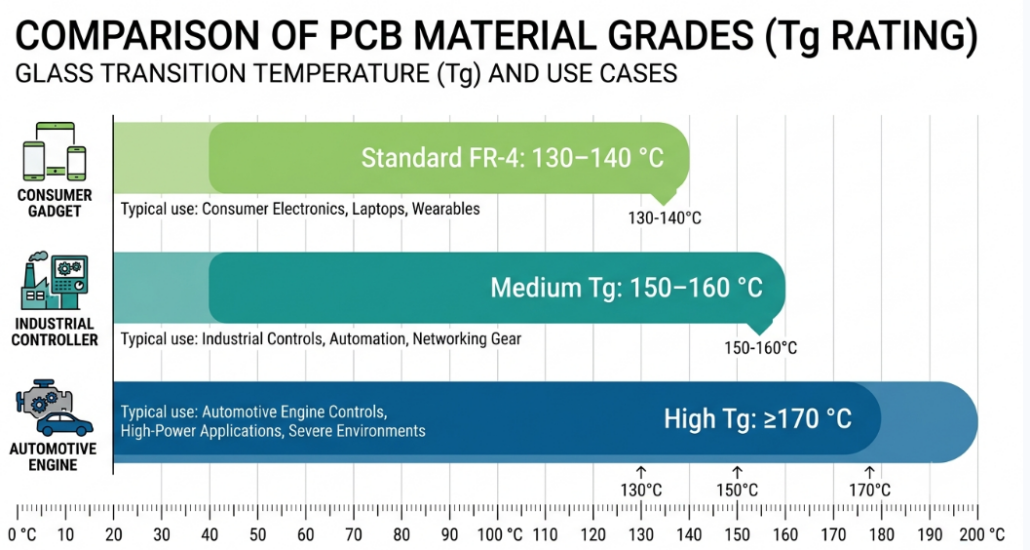
All FR4 is not made equal, and the easiest method of distinguishing the grades is by their Tg value. Laminates are generally classified into three categories according to the glass transition point (Tg). A high Tg PCB is typically a PCB that is made with a laminate that has a Tg of 170 °C or higher. In addition to the overall figure, higher Tg resins are also likely to provide a lower coefficient of thermal expansion (CTE), greater moisture resistance, and greater chemical and mechanical heat resistance. The bottom line: You're purchasing margin; the more you're below the Tg, the more stable and reliable the board will be.
How Tg Value Affects PCB Performance and Reliability
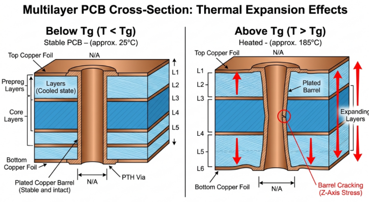
Impact on Thermal Stability and Dimensional Changes
All kinds of PCB materials expand due to heat. FR4 expands at a low, predictable rate below Tg. The issue is what happens above Tg, as the Z-axis CTE can suddenly increase by 3 times or more. It is that Z-axis expansion that is the true reliability foe. The laminate expands in a thickness direction and causes the copper barrels within your plated-through holes and vias to expand. The greater the Tg Value, the broader the temperature range in which the material remains in a stable low expansion range. The benefits in practice are:
- Minimized Z-axis expansion stress on plated TH/vias
- Improved dimensional stability for fine line and high-density designs.
- Reduced risk of delamination and measling under thermal load.
- Improved multilayer stackup registration.
Importance in Lead-Free Soldering and High-Temperature Environments
That's where it left off, with a majority of the industry having a choice. As a result of the RoHS driving the shift to lead-free solder, particularly the rise in the peak reflow temperature moved from the former eutectic 63/37 near 215 °C to the new SAC305 world of 245 - 260 °C. The standard 130 °C FR4 material is spending a significant portion of the reflow profile above its Tg, where it is soft and susceptible to mechanical stresses being applied to the board.
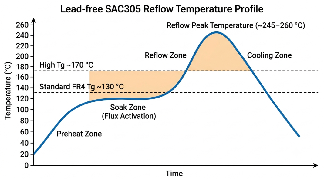
Doubling that by the two or three reflow passes, a double-sided assembly can endure, but the damage accumulates quickly. This is much better managed by high Tg materials. They remain closer to their rigid state throughout more of the profile, withstand delamination during repeated heating, and withstand the rework cycles required during actual production. In the world of automotive under-hood, it is no different, and LED lighting applications are constantly subjected to continuous exposure to heat, and a comfortable heat gap to Tg is what pays for years of trouble-free service.
Selecting the Optimal Tg Value for Your Application
Matching Tg to Industry Requirements (Consumer, Industrial, Automotive)
The easiest option is to begin with the thermal reality of your application. Each industry has its own temperature and reliability requirements, and the appropriate Tg follows.
- Consumer Electronics: Toys, remote controls, simple IoT gadgets, and low-power consumer boards typically have low power consumption and run for short periods of time. In general, standard 130 – 140 °C FR4 is adequate and inexpensive.
- Industrial and telecom: Continuous heat and increased layers for power supplies, motor controllers, and networking equipment. Commonly used is a medium to high Tg (150 – 170 °C).
- Automotive and aerospace: Under-hood modules, EV power electronics, and avionics require a high Tg (≥ 170 °C), frequently combined with high Td and close CTE control, sometimes in combination with Class 3 reliability.
Balancing Performance, Cost, and Manufacturing Feasibility
Normally, a high Tg laminate is more expensive than a normal FR4 laminate, so the idea is to purchase only the amount of thermal margin that your design requires. Consider Tg selection as a balancing act between three forces.
| Factor | Lean Toward Standard Tg | Lean Toward High Tg |
|---|---|---|
| Operating temperature | Low, stable | High or cyclic |
| Layer count | 1 – 4 layers | 6+ layers, dense vias |
| Soldering | Single lead-free reflow | Multiple reflows/rework |
| Reliability class | IPC Class 1 – 2 | IPC Class 2 – 3 |
| Budget sensitivity | Tight | Reliability prioritized |
Keep in mind that the cost of materials is just one line item. Don't consider just the price of the board; a failing board in the field is much more expensive than the difference in laminate.
Manufacturing Considerations for High Tg Value PCBs
Process Adjustments and Material Handling Best Practices
The higher Tg resins are harder, and that is why they require more careful processing. The more cross-linked resin system that provides you with thermal stability is also stiffer and thus will drill differently and laminate differently than standard FR4. Some of the key process changes that fabricators make in using high Tg material are:
Drilling: Higher Tg laminates cause more abrasion, drill bit feed, speed, and replacement rates are optimized to prevent nail-heading and hole wall roughness.
Lamination: The lamination temperatures are usually higher, and the cure cycles are longer for these resins to be fully crosslinked.
Desmear: Chemically-resistant resin requires a modified desmear process to clean and prepare hole walls for plating.
Material storage: Prepreg and cores are stored in controlled humidity to avoid moisture absorption, which may lead to delamination during reflow.
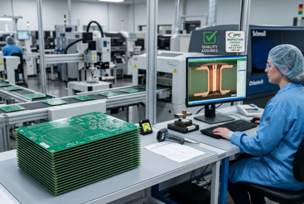
Quality Control to Maintain Consistent Tg Performance
A datasheet Tg is great, but if the finished board is not actually achieving it, then it isn't. Hence, QC testing for high Tg production is not just a matter of ensuring dimensions, but also a matter of ensuring thermal performance. Good fabricators will check the laminate upon receipt from suppliers against the supplier's certification and perform thermal stress testing, such as solder float and thermal cycling, to ensure that the board can withstand the conditions for which it was rated. The cross-section microsectioning inspects plated through-hole integrity and searches for any delamination or barrel cracking post-stress. These checks are linked to the manufacturing process and back to the IPC-6012 performance standard, so you'll know that what you paid for was what you got in terms of the Tg Value.
JLCPCB's Expertise in High Tg Value PCB Production
Wide Selection of Certified High Tg Materials
JLCPCB provides a variety of certified laminates from standard, medium, and high Tg to perfectly match your application. Cost-effective FR4 130 – 140 °C for consumer gadgets or high Tg FR4 170 °C+ for automotive or industrial boards are all possible and available by way of a simple instant-quote interface.
Reliable Fabrication Ensuring Long-Term Board Stability
All of this means a stable board when it comes off the line. JLCPCB's boards are designed to withstand lead-free reflow, rework, and years of thermal cycling in the field with the use of certified high Tg laminates and consistent process control, along with IPC-based quality checks. When you're ready to implement these principles, there's an easy way to create a board whose Tg Value lives up to its mission. JLCPCB's material selection tools and DFM tools will help you do just that.
FAQ about PCB Tg Value
Q: What is the Tg value in PCB and why does it matter?
Tg value is the glass transition temperature at which a PCB's resin changes from a rigid glassy state to a soft rubbery state. It matters because above Tg the board's thermal expansion accelerates sharply, stressing vias and solder joints, so a higher Tg means more reliability margin.
Q: Is Tg the maximum operating temperature of a PCB?
No. Tg is a reversible transition point, not a destruction or maximum rating. Your board can briefly reach Tg during reflow without permanent damage, but for long-term reliability, you should keep sustained operating temperatures comfortably below it.
Q: What is the difference between standard FR4 and high Tg PCB material?
Standard FR4 has a Tg of roughly 130–140 °C, while a high Tg PCB uses a laminate rated at 170 °C or above. High Tg material also offers lower thermal expansion, better moisture resistance, and improved survival through lead-free reflow.
Q: When should I choose a high Tg PCB over standard FR4?
Choose high Tg for high-temperature, high-power, or thermally cycling environments such as automotive, industrial, and dense multilayer boards. For low-power, cool-running consumer electronics, standard FR4 is usually sufficient and more cost-effective.
Conclusion
Choosing the right Tg value is one of the smartest decisions you can make when designing a reliable PCB. It’s not just another number on a datasheet — it’s the key to surviving lead-free soldering, thermal cycling, and demanding operating environments without delamination, via failure, or premature breakdown.
Whether you’re building consumer gadgets or mission-critical automotive and industrial electronics, matching your Tg requirements to real-world thermal demands ensures better dimensional stability, stronger plated through-holes, and longer product lifespan. High Tg materials may cost a little more upfront, but they dramatically reduce field failures and expensive redesigns.
At JLCPCB, we offer a wide range of certified high Tg FR4 materials, combined with precise manufacturing processes and strict quality control, so you can confidently bring your designs to life.
Ready to build more reliable boards? Upload your design today and select the perfect Tg material for your next project.
Keep Learning
Your Ultimate Guide to PCB Rulers
In the world of PCB design and manufacturing, having the right tools is crucial for achieving accuracy and precision. One such tool that has gained popularity among professionals and hobbyists is the PCB ruler. This specialized measuring tool is designed to provide accurate measurements, reference information, and component footprints, assisting designers, engineers, technicians, and assemblers in various stages of PCB development. In this guide, we'll explore what a PCB ruler is, the features and mea......
Understanding the Materials Used in PCBs: Selection, Types, and Importance
Key Takeaways FR-4 is the go-to material for most cost-effective and reliable PCBs. Use Rogers for high-frequency and RF applications to reduce signal loss. Higher copper weight (2oz) improves current and heat handling. Choose High-Tg substrates for better thermal stability in multilayer boards. Green LPI soldermask offers the best balance of performance and inspection. Printed circuit boards (PCBs) are an essential component of modern electronics. These boards connect and support electronic component......
How to Select Tg of PCB ?
What is the Tg of PCB? In PCB manufacturing, "Tg" stands for Glass Transition Temperature. It is the temperature at which the PCB substrate material transitions from a rigid, glassy state to a soft, rubbery state. PCBs are flame-retardant (UL94 V-0) and do not burn easily; instead, they soften above Tg. The Critical Correlation Between Tg and Z-Axis CTE (Coefficient of Thermal Expansion) When the temperature exceeds the Tg point, the PCB substrate material (such as standard FR-4) undergoes a physical ......
How to Choose the Thickness of PCB
First, In the world of electronic products, the PCB is often referred to as the "heart" of the device. It interconnects all components, making board thickness one of the most important parameters. Choosing the right PCB thickness directly affects the electrical performance, mechanical stability, thermal management, and long-term reliability of the final electronic product. The process of selecting PCB thickness is influenced by various factors, such as product application scenarios, board material, an......
PCB Copper Pour Basics
What is Copper Pour in PCB Design? Copper pour refers to the technique of filling unused areas of a PCB's copper layers with solid copper planes. These planes are connected to power or ground nets, creating a continuous conductive path. Copper pour is typically used in the power and ground planes, as well as in signal layers for specific purposes. Purpose and Benefits of Copper Pour: Copper pour is primarily used to fill unused areas on PCB copper layers with solid (or hatched) copper connected to pow......
How to Prevent Solder Bridges for Superior PCB Quality and Reliability
Key Takeaways Solder bridges are a leading cause of SMT failures on fine-pitch components. Prevent them with proper solder mask dams (0.075–0.1mm), optimized stencil design, and controlled reflow profiles. Combine good DFM practices with AOI + X-ray inspection for maximum reliability. Professional manufacturing and early DFM review significantly boost first-pass yield and reduce costly rework. You have experienced the post-reflow sadness and eyed the board that failed on the first reflow, if you have ......