
How to Choose the Right PCB Laminate: A Practical Guide for Performance, Cost & Reliability
7 min
- Introduction: Why Laminate Selection Matters More Than Ever
- Understanding PCB Laminates and Their Core Components
- Key Factors to Consider When Choosing a Laminate
- Popular Laminate Types and How to Compare Them
- Design, Manufacturing, and JLCPCB’s Professional Expertise
- Conclusion: Select the Right Laminate with Confidence
- FAQ
Selecting the correct PCB laminate is one of the most important decisions in any board design. The laminate determines electrical performance, thermal behavior, mechanical strength, cost, and long-term reliability. A poor choice can lead to signal integrity problems, delamination during reflow, or excessive warpage in production. Engineers who understand laminate properties can avoid these issues and achieve better results at lower cost.
Introduction: Why Laminate Selection Matters More Than Ever
The Direct Impact on Signal Integrity and Cost
Modern designs push data rates higher every year. At 5 Gbps and above, even small differences in dielectric constant (Dk) or dissipation factor (Df) can cause impedance mismatches and signal loss. Choosing the wrong laminate can force designers to add extra layers or use more expensive materials later, increasing both cost and lead time. Conversely, selecting the right laminate from the start can reduce layer count by 1–2 layers and cut material cost by 15–25%.
New Challenges in High-Speed and High-Reliability Projects
Automotive, 5G, and medical applications now demand higher Tg, lower CTE, and better thermal conductivity. At the same time, environmental regulations push for halogen-free and RoHS-compliant materials. Balancing all these requirements makes laminate selection more complex than ever.
Understanding PCB Laminates and Their Core Components
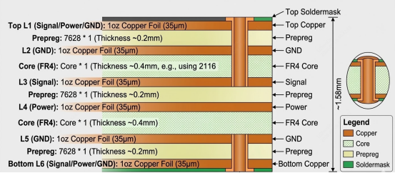
What Makes Up a Laminate
A PCB laminate consists of three main elements: woven glass fabric for mechanical strength, epoxy resin system for insulation and bonding, and copper foil for conductivity. The glass style (106, 2116, 7628, etc.) and resin formulation determine the final electrical and thermal properties. Thicker glass styles give better rigidity but higher Dk; finer styles reduce Dk but increase cost.
Standard FR-4 vs Specialty Laminates
Standard FR-4 remains the workhorse for most designs because of its low cost and wide availability. However, specialty laminates — high-Tg, low-loss, halogen-free, or metal-core — are increasingly used when standard FR-4 cannot meet thermal, speed, or environmental requirements. Understanding the differences early prevents costly redesigns later.
Key Factors to Consider When Choosing a Laminate
Electrical Properties (Dk, Df, Impedance Control)
Dielectric constant (Dk) and dissipation factor (Df) directly affect signal propagation speed and loss. For high-speed designs, lower Dk and Df materials reduce insertion loss. JLCPCB’s standard FR-4 has Dk around 4.5 at 1 GHz; low-loss options drop to 3.8–4.0. Tight impedance control (±10% or better) requires stable Dk across frequency and temperature.
Thermal Performance (Tg, Td, CTE)
Glass transition temperature (Tg) indicates when the resin softens. Higher Tg (170°C+) materials withstand multiple lead-free reflow cycles without delamination. Decomposition temperature (Td) shows when the material starts breaking down — aim for Td >340°C for reliability. Z-axis CTE should be below 50 ppm/°C to minimize via stress.
Mechanical Strength, Cost, and Compliance Needs
Mechanical strength affects drilling and assembly yield. Cost increases with Tg, low-loss properties, or halogen-free certification. Environmental requirements (RoHS, halogen-free) have become standard in many markets. Always balance these factors against the actual operating environment and expected product lifetime.
Table 1: Laminate Selection Factors Overview
| Factor | Standard FR-4 | High-Tg FR-4 | Low-Loss Halogen-Free | Key Consideration |
| Dk (@1GHz) | 4.4–4.7 | 4.3–4.6 | 3.8–4.1 | Signal speed & impedance control |
| Df (@1GHz) | 0.018–0.022 | 0.016–0.019 | 0.008–0.012 | Insertion loss at high frequency |
| Tg (°C) | 130–140 | 170–180 | 150–170 | Reflow cycles & thermal cycling |
| Td (°C) | 310–330 | 350–380 | 340–370 | Long-term thermal reliability |
| Cost Index | 1.0 | 1.3–1.6 | 1.8–2.5 | Budget vs performance trade-off |
Popular Laminate Types and How to Compare Them
High-Tg, Low-Loss, Halogen-Free and Metal-Core Options
High-Tg laminates (170°C+) are ideal for automotive and industrial boards that experience wide temperature swings. Low-loss materials (Df <0.012) suit 5G, PCIe, and RF applications. Halogen-free versions meet strict environmental standards while maintaining good thermal performance. Metal-core (aluminum or copper) laminates are used when heat dissipation is the primary concern.
Material Comparison Table
| Laminate Type | Tg (°C) | Dk (1 GHz) | Df (1 GHz) | CTE-Z (ppm/°C) | Typical Applications |
| Standard FR-4 | 135 | 4.5 | 0.020 | 55 | General consumer & industrial |
| High-Tg FR-4 | 175 | 4.4 | 0.017 | 45 | Automotive, multiple reflow |
| Low-Loss Halogen-Free | 160 | 3.9 | 0.010 | 50 | 5G, high-speed digital |
| Metal-Core (Aluminum) | N/A | 4.2 | 0.018 | 20–25 | LED lighting, power electronics |
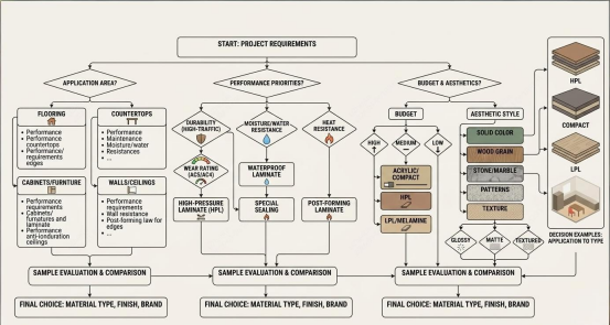
Quick Selection Guide by Application
For cost-sensitive consumer products, standard FR-4 is usually sufficient. Automotive and server designs benefit from high-Tg materials. High-frequency RF and 5G boards require low-loss laminates. LED or high-power applications often use metal-core laminates for superior heat dissipation.
Design, Manufacturing, and JLCPCB’s Professional Expertise
Essential DFM Rules for Different Laminates
Different laminates require different design rules. High-Tg materials need slightly larger annular rings to compensate for higher Z-axis expansion. Low-loss laminates are more sensitive to trace geometry, so maintain consistent width and spacing. Always verify minimum drill-to-copper clearance with the chosen material.
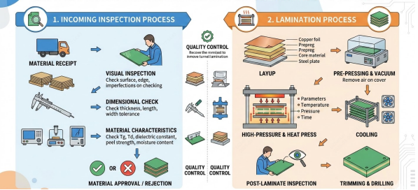
Advanced Process Controls for Consistent Quality
JLCPCB controls laminate quality through incoming material inspection, precise lamination pressure/temperature profiles, and post-lamination testing. Every panel includes test coupons for Tg, impedance, and thermal stress verification.
Why JLCPCB Makes Laminate Selection Easier and More Reliable
JLCPCB maintains a large inventory of verified laminates, including standard FR-4, high-Tg, halogen-free, and low-loss grades. Our online quoting system shows material availability instantly. The free DFM check automatically flags issues related to the selected laminate, and our engineering team provides optimization suggestions within hours. Quick-turn service (as fast as 24 hours for prototypes) lets you validate your laminate choice early.
Conclusion: Select the Right Laminate with Confidence
Choosing the right PCB laminate directly affects signal integrity, thermal reliability, cost, and time-to-market. By understanding Dk, Df, Tg, Td, and CTE, and matching them to your specific application, you can avoid costly redesigns and field failures.
At JLCPCB, laminate selection is made simple. With a wide range of in-stock materials, professional DFM support, precise impedance control, and fast turnaround, we help engineers turn designs into reliable products quickly and economically. Upload your design today at jlcpcb.com and let our team help you choose — and manufacture — the perfect laminate for your project.

FAQ
Q1: What is the most important factor when choosing a PCB laminate?
A: Electrical requirements (Dk/Df) and thermal demands (Tg/Td) are usually the top priorities, followed by cost and environmental compliance.
Q2: How much more expensive are high-Tg or low-loss laminates?
A: Typically 30–60% higher than standard FR-4, but they often reduce layer count and improve long-term reliability.
Q3: Can I mix different laminates in one board?
A: Yes, but CTE matching and symmetric stackup are critical to prevent warpage and ensure reliable lamination.
Q4: Does JLCPCB provide support for laminate selection?
A: Yes. We offer free DFM checks, real-time material availability, and engineering recommendations to help you select the best laminate for your project.
Keep Learning
How Modular PCB Design Simplifies Complex Electronics Projects
Key Takeaway Modular PCB design simplifies complex electronics by breaking boards into independent, reusable functional blocks with clear interfaces. It boosts reusability, speeds up debugging, enhances team collaboration, and reduces errors.Shift from flat to modular design for faster development and more scalable, reliable PCBs. Ever seen a 400+ component schematic and got your head scrambled before even beginning routing? You are not alone. With the ever-increasing density of electronics combined w......
Your Ultimate Guide to PCB Rulers
In the world of PCB design and manufacturing, having the right tools is crucial for achieving accuracy and precision. One such tool that has gained popularity among professionals and hobbyists is the PCB ruler. This specialized measuring tool is designed to provide accurate measurements, reference information, and component footprints, assisting designers, engineers, technicians, and assemblers in various stages of PCB development. In this guide, we'll explore what a PCB ruler is, the features and mea......
Understanding the Materials Used in PCBs: Selection, Types, and Importance
Key Takeaways FR-4 is the go-to material for most cost-effective and reliable PCBs. Use Rogers for high-frequency and RF applications to reduce signal loss. Higher copper weight (2oz) improves current and heat handling. Choose High-Tg substrates for better thermal stability in multilayer boards. Green LPI soldermask offers the best balance of performance and inspection. Printed circuit boards (PCBs) are an essential component of modern electronics. These boards connect and support electronic component......
How to Select Tg of PCB ?
What is the Tg of PCB? In PCB manufacturing, "Tg" stands for Glass Transition Temperature. It is the temperature at which the PCB substrate material transitions from a rigid, glassy state to a soft, rubbery state. PCBs are flame-retardant (UL94 V-0) and do not burn easily; instead, they soften above Tg. The Critical Correlation Between Tg and Z-Axis CTE (Coefficient of Thermal Expansion) When the temperature exceeds the Tg point, the PCB substrate material (such as standard FR-4) undergoes a physical ......
How to Choose the Thickness of PCB
First, In the world of electronic products, the PCB is often referred to as the "heart" of the device. It interconnects all components, making board thickness one of the most important parameters. Choosing the right PCB thickness directly affects the electrical performance, mechanical stability, thermal management, and long-term reliability of the final electronic product. The process of selecting PCB thickness is influenced by various factors, such as product application scenarios, board material, an......
PCB Copper Pour Basics
What is Copper Pour in PCB Design? Copper pour refers to the technique of filling unused areas of a PCB's copper layers with solid copper planes. These planes are connected to power or ground nets, creating a continuous conductive path. Copper pour is typically used in the power and ground planes, as well as in signal layers for specific purposes. Purpose and Benefits of Copper Pour: Copper pour is primarily used to fill unused areas on PCB copper layers with solid (or hatched) copper connected to pow......