
Why Glass Transition Temperature Is Key to Reliable PCB Performance
13 min
- Understanding Glass Transition Temperature in PCB Materials
- How Tg Directly Affects PCB Reliability
- Choosing the Right Materials Based on Tg Requirements
- Manufacturing Considerations for High-Tg PCBs
- JLCPCB's Expertise in High-Tg PCB Manufacturing
- Frequently Asked Questions (FAQ)
Ever had a load of freshly reflowed PCBs in the oven, then found out when you looked at it that there were delamination blisters or broken barrel vias? Should it be the case, it may not be your reflow profile or your solder paste. It could be baked into the substrate that you have your board composed of. One of the most important, yet often neglected, material characteristics of your PCB laminate that will make the difference between your board making it through the manufacturing process and making it to the field is the glass transition temperature of your laminate.
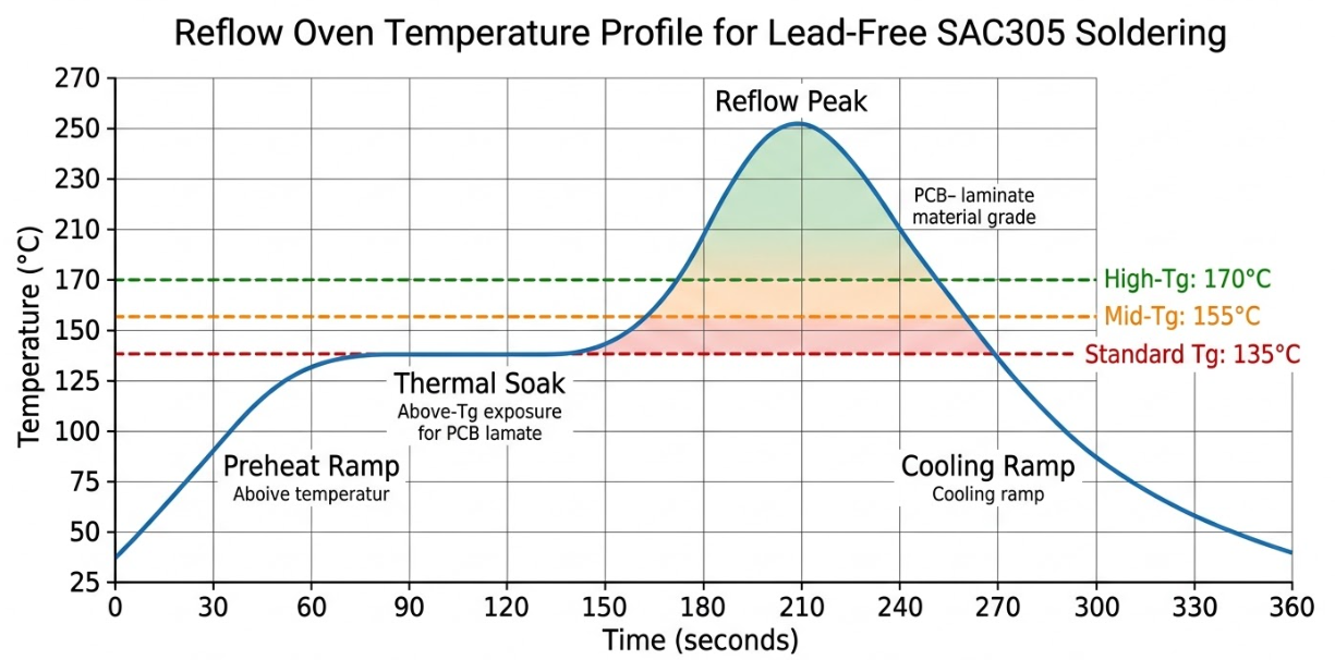
All resin systems employed in PCB production act like a stiff, glassy substance under a specific temperature level. Cross that limit and the resin becomes soft, its growth rate soars, and mechanical strength begins to fail. That temperature is the glass transition temperature, which is usually denoted as Tg. As the industry is now going to lead-free soldering and the peak reflow temperature is now 250 to 260 degrees Celsius, knowledge of Tg is no longer a luxury. Any engineer who desires good boards must have this.
This article is going to delve into the depths of what exactly a glass transition temperature is, how to measure it, why it is important to PCB reliability, and how to select the appropriate material grade for your project. The manufacturing considerations that arise when dealing with high-Tg laminates will also be examined, and how JLCPCB addresses them in its production.
Understanding Glass Transition Temperature in PCB Materials
What Glass Transition Temperature Means and How It Works
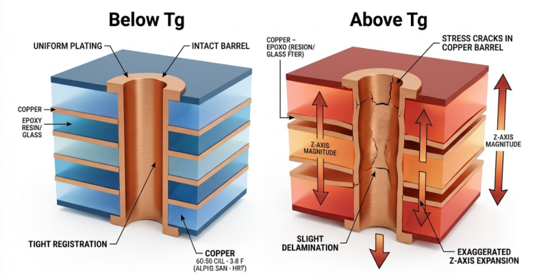
Glass transition temperature: The temperature at which a polymer is hard and rigid, and changes to soft and rubbery. This should not be taken as a melting point. The substance does not melt at Tg. Rather, it slowly changes its molecular behavior. The polymer chains of the epoxy resin below Tg are somewhat fixed in position, providing structural rigidity to the laminate. At temperatures above Tg, such chains acquire sufficient thermal energy to start moving more freely, and the material becomes much more flexible and dimensionally unstable.
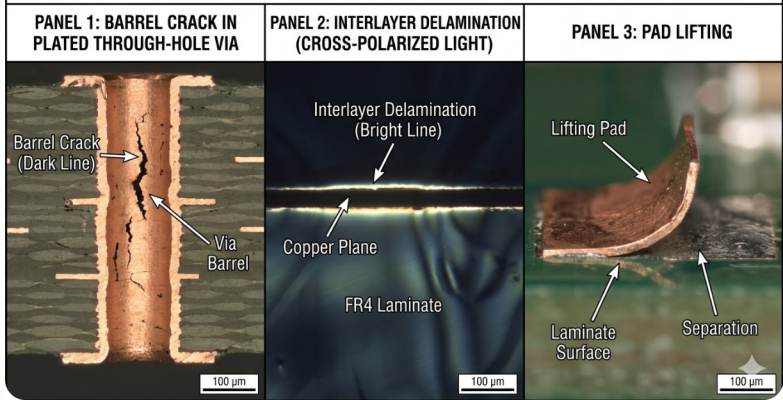
In the case of PCB engineers, the useful implication is simple. At temperatures below Tg, the z-axis coefficient of thermal expansion (CTE) of FR4 will generally be 50 to 70 ppm/degree Celsius. When you get above Tg, this figure soars to 250 to 300 ppm per degree Celsius. Four times five times the rate of expansion. It is this mismatch that causes barrel cracks, corner cracks, and pad lifting in plated through-holes. It is also the process that causes interlayer delamination when the resin pulls off internal copper planes due to thermal stress.
Measuring Tg and What the Values Tell Us
Tg is not a constant fixed number that you measure at any one time, and that is it. Various methods of measurement give a marginally different value, and it is important to know these differences when comparing datasheets of different suppliers of laminate.
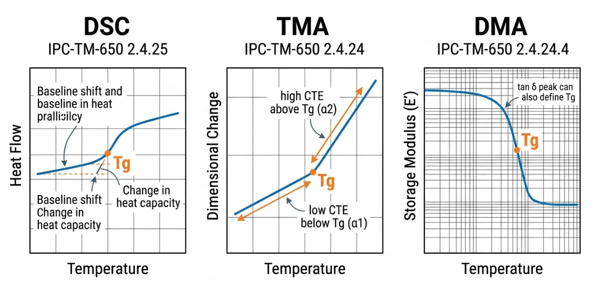
The three primary methods used in the industry are:
1.Differential Scanning Calorimetry (DSC) - Measures the change in heat capacity as the material is heated. The Tg is identified at the inflection point where the heat flow curve shifts. This is the most commonly referenced method and follows IPC-TM-650 2.4.25.
2.Thermomechanical Analysis (TMA) - Measures dimensional change as a function of temperature. The Tg is identified where the CTE curve shows a sharp increase. This method follows IPC-TM-650 2.4.24C and also provides z-axis expansion data.
3.Dynamic Mechanical Analysis (DMA) - Measures changes in the material's stiffness and damping as a function of temperature. DMA is the most sensitive of the three and typically reports Tg values 10 to 25 degrees Celsius higher than TMA.
| Measurement Method | IPC Standard | What It Measures | Typical Tg Offset |
| DSC | IPC-TM-650 2.4.25 | Heat capacity change | Baseline reference |
| TMA | IPC-TM-650 2.4.24C | Dimensional change (CTE) | 0 to -10 degrees Celsius vs DSC |
| DMA | N/A (ASTM methods) | Stiffness and damping | +10 to +25 degrees Celsius vs DSC |
How Tg Directly Affects PCB Reliability
Impact on Mechanical Strength and Dimensional Stability
At the Tg of your PCB, or anything close to it, mechanical reliability is getting dangerous. The resin structure becomes soft,t and the board is no longer able to hold tight dimensional tolerances. In the case of multilayer boards, it implies a shift of the internal layers relative to one another, resulting in registration errors that undermine via-to-pad alignment.
The decrease in the mechanical strength is not only a hypothetical issue. The maximum reflow temperature of SAC305 solder paste is 245 to 260 degrees Celsius in lead-free assembly. The FR4 board, having a Tg of 130 to 140 degrees Celsius, is working over 100 degrees higher than its glass transition when reflowing. Each degree higher than Tg increases the rate at which resin breaks down, and in general, a 10 deg Celsius rise in the temperature doubles the rate of polymer breakdown.
Performance Under Thermal Cycling and High Operating Temperatures
In thermal cycling, a glass transition temperature is used to separate reliable boards from field failures. Whenever a PCB is heated up when it is in operation and cooled down when it is idle, it is subjected to a thermal cycle. Should these cycles drive the board beyond its Tg, the repetitive expansion and contraction result in fatigue stress on all the plated vias and all the copper-to-resin interfaces in the board.
The math of reliability is strong. A board that works at 80 percent of its Tg in absolute temperature units should last many thousands of thermal cycles without problems. A board whose Tg is surpassed by a board can start exhibiting failures in a few hundred cycles. This is the reason why high-Tg materials are required in such industries as automotive, aerospace, and industrial controls, although the average operating temperature may appear to be relatively modest. The damage is caused by the peak temperatures during power surges, extremes in the environment, and assembly.
Choosing the Right Materials Based on Tg Requirements
Standard FR4 vs High-Tg and Ultra-High-Tg Laminates
The PCB industry categorizes FR4 laminates into three general Tg tiers. Each tier corresponds to a different resin formulation with progressively better thermal performance, but also increasing cost.
| Property | Standard FR4 | Mid-Tg FR4 | High-Tg FR4 |
| Tg (DSC) | 130 to 140 degrees Celsius | 150 to 155 degrees Celsius | 170 to 180 degrees Celsius |
| Td (Decomposition) | 300 to 310 degrees Celsius | 320 to 340 degrees Celsius | 340 to 350 degrees Celsius |
| Z-axis CTE (below Tg) | 55 to 70 ppm per degree Celsius | 45 to 55 ppm per degree Celsius | 40 to 50 ppm per degree Celsius |
| Z-axis CTE (above Tg) | 250 to 300 ppm per degree Celsius | 200 to 250 ppm per degree Celsius | 180 to 230 ppm per degree Celsius |
| T260 (minutes) | 5 to 10 | 15 to 30 | 30 to 60+ |
| T288 (minutes) | 2 to 5 | 5 to 15 | 15 to 30+ |
| Typical Materials | Shengyi S1000, NP-140 | NP-155F, Shengyi S1000H | Shengyi S1000-2M, Isola 370HR, ITEQ IT-180A |
| Cost Relative to Standard | 1x | 1.1 to 1.3x | 1.3 to 1.6x |
Standard FR4 (Tg 130-140 degrees Celsius) is perfectly fine in consumer electronics, simple LED boards, and environments where the board will not be reflowed at temperatures above 230 degrees Celsius or operated at temperatures above 100 degrees Celsius. It is the most affordable one and can be purchased by practically any fabricator.
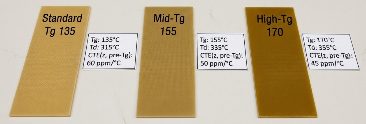
Most lead-free applications have a sweet spot of Mid-Tg FR4 (Tg 150-155 degrees Celsius). It offers sufficient thermal margin to normal SAC305 reflow profiles at affordable prices. This is usually the lowest recommended grade in multilayer boards with six or more layers since the extra reflow cycles during assembly impose more cumulative thermal stress.
High-Tg FR4 (Tg 170-180 degrees Celsius) is required in high operating temperature applications, high reflow requirements, thick boards with high aspect ratio vias, or in any application where the requirement is thermal reliability. This grade is usually a baseline requirement in automotive, aerospace, server, and industrial applications.
Matching Tg to Application Demands for Optimal Results
Selecting the right Tg grade is not just about picking the highest number available. Over-specifying material adds cost without adding value. Here is a practical framework for matching Tg to your application:
- Consumer electronics, IoT devices, and simple 2-layer boards: Standard FR4 (Tg 130-140 degrees Celsius) is typically sufficient. These boards see one or two reflow cycles and operate well within thermal limits.
- General-purpose multilayer boards (4 to 8 layers) with lead-free assembly: Mid-Tg FR4 (Tg 150-155 degrees Celsius) provides the thermal margin needed for reliable lead-free reflow without excessive cost increase.
- Automotive electronics, industrial controls, and power modules: High-Tg FR4 (Tg 170+ degrees Celsius) is the standard requirement. These applications face wide temperature swings and demand long operational lifetimes.
Another factor that should be taken into consideration is the decomposition temperature (Td), and this is the temperature at which the resin starts to chemically degrade permanently. Where Tg is a reversible transition, Td is an irreversible damage. An excellent high-Tg laminate will possess a Td of 340 degrees Celsius and above, which offers a significant safety factor over even the most aggressive lead-free reflow profiles.
Manufacturing Considerations for High-Tg PCBs
Process Adjustments for High-Tg Materials
High-Tg laminates cannot be simply replaced by another material on the production line. The increased cross-link density and various resin chemistries of high-Tg materials demand certain process modifications at various fabrication stages.
Differences start to arise in drilling. High-Tg resins are more abrasive and tough on drill bits. The feed rates and drill speeds should be adjusted to ensure that the amount of heat generated and the smear along the hole walls are minimized. Incorrect drilling parameters may result in a rough wall of the holes that affects the adhesion of copper plating in the further metallization processes.
High-Tg materials are increasingly sensitive to the desmear procedure. The more resistant the resin is to the chemical desmear procedure, the longer it requires exposure or the harsher the chemistry. Unfinished desmears leave traces of resin onto the inside copper layers, which may cause failure of reliability at the interconnect.
High-Tg prepreg lamination profiles are also not identical to standard materials. Tg resins normally need increased temperatures and longer times to cure in order to reach a full cure. Lack of cure leads to a laminate that would not meet its rated Tg, which is the point of using the high-quality material in the first place.
Ensuring Consistent Tg Performance During Production
Several factors can degrade the actual achieved Tg of the finished board below the nominal material specification:
1.Incoming material verification through lot-level testing ensures that the raw laminate meets the specified Tg. Variations between material batches from the supplier must be caught before they enter production.
2.Lamination cycle optimization ensures full cure of the resin system. Under-curing reduces Tg, while over-curing can make the material brittle and reduce its thermal shock resistance.
3.Moisture control throughout the process is essential. FR4 laminates absorb moisture from the environment, and trapped moisture can cause delamination during thermal processing. Pre-baking panels before lamination and reflow is a standard practice for high-Tg production.
4.Post-lamination thermal testing using DSC or TMA on coupon samples verifies that the achieved Tg matches the expected value for the material grade.
JLCPCB's Expertise in High-Tg PCB Manufacturing
Advanced Material Selection and Process Control
JLCPCB provides three grades of FR4 Tg to suit the whole spectrum of application demands. FR4 TG135-140 is the default standard that applies to 1 to 6-layer boards. FR4 TG155 with Nan Ya Plastics NP-155F laminate is a cheaper step up to applications with better thermal performance needs. In the most arduous thermal applications, FR4 TG170 is based on the Shengyi S1000-2M material system, a proven high-Tg laminate with a long record of automotive and industrial success.
What is specifically useful about this material choice as it applies to impedance-controlled designs is that the impedance calculator offered by JLCPCB is set to the dielectric characteristics of NP-155F and S1000-2M. When you create your controlled impedance traces in the tools provided by JLCPCB, but assemble with a new Tg grade, your impedance profile will not correspond to the calculated values. This is a minor but important fact that is ignored by most engineers.
Rigorous Quality Assurance for Reliable High-Temperature Boards
Production of highly-Tg requires more than the utilization of the appropriate raw materials. Process controls practiced at JLCPCB are in line with the IPC-6012 qualification requirements that require each and every board produced to be within its Tg specifications. This involves inspection of incoming materials, lamination cycle, and post-fabrication reliability on production coupons.
The fabrication process is modified to accommodate the various drilling, desmear, and lamination requirements of the TG155 or TG170 material options for boards manufactured using the TG155 or TG170 material options. The outcome is uniform plated through-hole characteristics with high aspect ratio vias, where the thermal expansion difference between copper and resin would have been a reliability issue.
Frequently Asked Questions (FAQ)
Q: What is the glass transition temperature of standard FR4?
Standard FR4 laminate has a glass transition temperature in the range of 130 to 140 degrees Celsius when measured by DSC (Differential Scanning Calorimetry). This is the most common PCB substrate material and is suitable for general-purpose electronics that do not face extreme thermal demands.
Q:Why do lead-free assemblies require higher Tg materials?
Lead-free solder alloys like SAC305 melt at approximately 217 to 220 degrees Celsius, compared to 183 degrees Celsius for traditional eutectic tin-lead solder. The peak reflow temperatures for lead-free assembly reach 245 to 260 degrees Celsius, which is 30 to 40 degrees higher than leaded processes.
Q: What is the difference between Tg and Td?
Tg (glass transition temperature) is a reversible transition. When the board cools back below Tg, the resin returns to its rigid glassy state. Td (decomposition temperature) is the temperature at which the resin begins irreversible chemical breakdown, typically defined as the point of 5 percent weight loss by thermogravimetric analysis (TGA). For standard FR4, Td is around 300 to 310 degrees Celsius.
Q: How do I know which Tg grade to specify for my PCB?
Consider three factors: your assembly process (leaded vs lead-free), your operating environment (maximum expected temperature), and the number of reflow cycles the board will undergo. For single-sided or simple double-sided boards with leaded assembly, standard Tg is fine.
Q: Can a PCB's actual Tg be lower than the material specification?
Yes. If the lamination process does not fully cure the resin system, the actual achieved Tg will be lower than the material's rated value. This is called under-cure and is one of the most common manufacturing-related Tg issues. Moisture absorption can also effectively lower the functional Tg of the material.
Keep Learning
How Modular PCB Design Simplifies Complex Electronics Projects
Key Takeaway Modular PCB design simplifies complex electronics by breaking boards into independent, reusable functional blocks with clear interfaces. It boosts reusability, speeds up debugging, enhances team collaboration, and reduces errors.Shift from flat to modular design for faster development and more scalable, reliable PCBs. Ever seen a 400+ component schematic and got your head scrambled before even beginning routing? You are not alone. With the ever-increasing density of electronics combined w......
Your Ultimate Guide to PCB Rulers
In the world of PCB design and manufacturing, having the right tools is crucial for achieving accuracy and precision. One such tool that has gained popularity among professionals and hobbyists is the PCB ruler. This specialized measuring tool is designed to provide accurate measurements, reference information, and component footprints, assisting designers, engineers, technicians, and assemblers in various stages of PCB development. In this guide, we'll explore what a PCB ruler is, the features and mea......
Understanding the Materials Used in PCBs: Selection, Types, and Importance
Key Takeaways FR-4 is the go-to material for most cost-effective and reliable PCBs. Use Rogers for high-frequency and RF applications to reduce signal loss. Higher copper weight (2oz) improves current and heat handling. Choose High-Tg substrates for better thermal stability in multilayer boards. Green LPI soldermask offers the best balance of performance and inspection. Printed circuit boards (PCBs) are an essential component of modern electronics. These boards connect and support electronic component......
How to Select Tg of PCB ?
What is the Tg of PCB? In PCB manufacturing, "Tg" stands for Glass Transition Temperature. It is the temperature at which the PCB substrate material transitions from a rigid, glassy state to a soft, rubbery state. PCBs are flame-retardant (UL94 V-0) and do not burn easily; instead, they soften above Tg. The Critical Correlation Between Tg and Z-Axis CTE (Coefficient of Thermal Expansion) When the temperature exceeds the Tg point, the PCB substrate material (such as standard FR-4) undergoes a physical ......
How to Choose the Thickness of PCB
First, In the world of electronic products, the PCB is often referred to as the "heart" of the device. It interconnects all components, making board thickness one of the most important parameters. Choosing the right PCB thickness directly affects the electrical performance, mechanical stability, thermal management, and long-term reliability of the final electronic product. The process of selecting PCB thickness is influenced by various factors, such as product application scenarios, board material, an......
PCB Copper Pour Basics
What is Copper Pour in PCB Design? Copper pour refers to the technique of filling unused areas of a PCB's copper layers with solid copper planes. These planes are connected to power or ground nets, creating a continuous conductive path. Copper pour is typically used in the power and ground planes, as well as in signal layers for specific purposes. Purpose and Benefits of Copper Pour: Copper pour is primarily used to fill unused areas on PCB copper layers with solid (or hatched) copper connected to pow......