Why High Tg FR4 Is the Smart Choice for Reliable High-Temperature PCBs
12 min
- Key Benefits of Choosing High Tg FR4
- When and Where to Use High Tg FR4
- Manufacturing Best Practices for High Tg FR4 PCBs
- JLCPCB's Expertise in High Tg FR4 PCB Production
- FAQ about High Tg FR4
- Conclusion
Key Takeaways
High Tg FR4 is the smart choice for reliable high-temperature PCBs, offering a glass transition temperature of 170°C+, superior thermal stability, lower Z-axis CTE, and reduced warpage compared to standard FR4. It excels in lead-free assembly and demanding environments such as automotive, industrial, and 5G applications, significantly improving long-term reliability while minimizing defects like via cracking and delamination. For engineers seeking durable performance, specifying high Tg FR4 delivers clear advantages with only a modest cost premium.
Ever taken a PCB out of a lead-free reflow oven and discovered that it had warped, delaminated, or developed internal stress? If that is the case, it may be a problem with standard FR4. However, there are laminate materials that can endure much higher temperatures prior to losing their structural rigidity, known as high Tg FR4, and this is becoming the preferred choice for engineers who won't settle for anything less. With the shrinking, density, and hotter nature of electronics, the thermal requirements of PCB substrates have been increasing. Automotive ECUs, industrial motor drives, LED power modules, and 5G infrastructure equipment are just a few examples of applications where operating temperatures exceed what standard FR4 was designed to withstand.
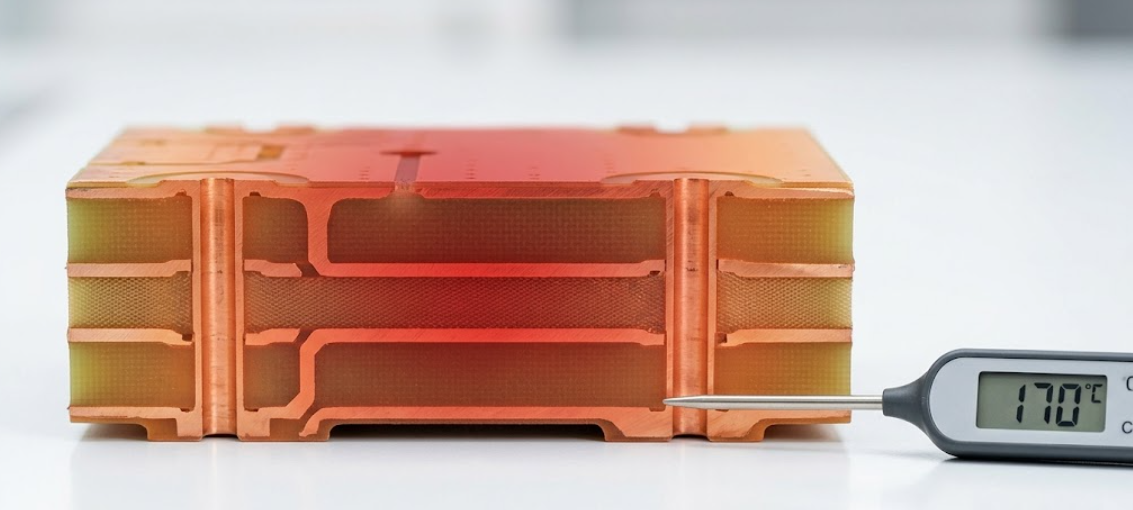
It is important to understand the "when" and "why" of specifying high Tg FR4, or else a product that may last 10 years in the field may fail. In this article, we will be delving deeper into the details of high Tg FR4, comparing it to regular FR4 boards, the situations in which it is most valuable, and how to utilize a high Tg FR4 PCB supplier to ensure steady and reliable outcomes.
What High Tg FR4 Means and How It Differs from Standard FR4
Tg is the glass transition temperature and is the point where a rigid polymer matrix starts to soften and change from a hard glassy to a rubbery state. The Tg for a standard FR4 laminate will be in the range 130-140 degrees Celsius. High Tg FR4, however, raises the threshold to 170 degrees Celsius or more; some grades can go up to 180 degrees Celsius and beyond.
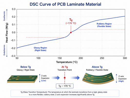
This distinction is significant, but not immediately apparent. As the temperature of a PCB approaches or reaches its Tg, the coefficient of thermal expansion (CTE) of the resin system changes dramatically, especially in the Z-axis. This Z-axis expansion creates massive stress on plated through holes and buried vias that cause electrical connections to break. Here is a side-by-side comparison of the key properties:
| Property | Standard FR4 (Tg ~130-140C) | High Tg FR4 (Tg ~170-180C) |
|---|---|---|
| Glass Transition Temperature | 130 - 140 C | 170 - 180 C |
| Decomposition Temperature (Td) | ~300 C | ~340 C |
| Z-axis CTE (below Tg) | ~50-60 ppm/C | ~40-50 ppm/C |
| Z-axis CTE (above Tg) | ~250-300 ppm/C | ~200-250 ppm/C |
| Moisture Absorption | ~0.15% | ~0.10-0.12% |
| Dielectric Constant (Dk) at 1 GHz | ~4.2-4.7 | ~4.2-4.6 |
| Typical Cost Premium | Baseline | 10-20% higher |
As you can see, the improvements in CTE and decomposition temperature are quite significant. These are not "marginal gains" - they are gains which directly correspond to reduced manufacturing defects and extended field life.
The Importance of Glass Transition Temperature (Tg) in PCB Materials
But why is the glass transition temperature important in practice? Consider this: Each thermal cycle your PCB experiences as it is being reflow soldered, in-circuit tested, and/or run normally can cause the laminate to expand and contract. The expansion rate becomes very high if the peak temperature is above the Tg.
As per IPC-4101 (base materials specification), laminates are divided into material groups, depending on their Tg, Td, and flammability values. High Tg materials are usually designated with one of the IPC-4101 /126 or /129 that have a minimum Tg of 170 C, either by DSC or TMA. To put it simply, if your board is going to get hotter than 130 degrees Celsius at any point in its life, whether it's while it's being built or while in service, you're running on the edge with standard FR4.
Key Benefits of Choosing High Tg FR4
Superior Thermal Stability and Reduced Warpage
One of the most common manufacturing headaches is board warpage, especially for larger-sized boards or thin boards during reflow. The board becomes mechanically soft when the laminate softens around its Tg. Throw in the fact that most real-world designs feature an uneven copper distribution, and you've got asymmetric thermal expansion, which bows or twists the panel.
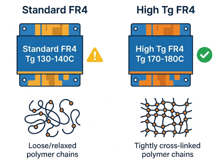
High Tg FR4 is still mechanically rigid at much elevated temperatures. This translates into a board that remains flat during reflow, which results in a more reliable solder joint. When boards are less than 1.0 mm or panels are larger than 250 mm x 200 mm, it can be important to specify high Tg material to minimize yield loss due to warpage. Less stress on plated through-holes during thermal cycling as a result of the reduced Z-axis CTE.
Better Performance in Lead-Free Assembly and High-Temperature Environments
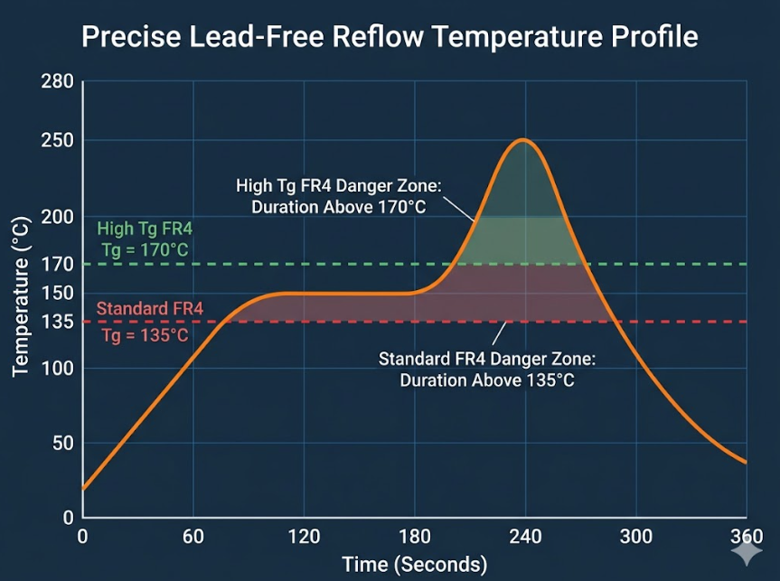
The transition to lead-free soldering worldwide made PCB materials a game-changer. The traditional solder, tin-lead type (Sn63/Pb37) has a melting point of 183°C. Peak reflow temperatures for the lead free alternatives (SAC305) are 245-260 degrees Celsius. During a reflow profile, the PCB is heated to over 230℃ for 60 or 90 seconds in a normal reflow process with no lead.
In the case of standard FR4 (135°C Tg), this means that the resin is already in the rubbery state and is already rapidly swelling out in the Z-axis. High Tg FR4 materials are not only above their Tg at reflow peak temperature, but also have much higher decomposition temperature (Td 340°C vs 300°C), so that there is a larger thermal safety margin. It isn't just an assembly advantage. Products used in harsh environments, such as automotive electronics under the hood, industrial control systems and outdoor telecom equipment are often exposed to ambient temperatures of 85 to 125 degrees Celsius. The high Tg FR4 assures the board's structural and electrical integrity over these operating requirements.
Enhanced Long-Term Reliability and Mechanical Strength
Reliability isn't only about surviving one thermal event. It's about withstanding thousands of thermal cycles during a product's life without degradation. High Tg FR4 material has been shown to perform well in accelerated life testing, such as thermal shock testing (IPC-TM-650 Method 2.6.7.2) and IST testing.
There are several reliability benefits, including:
- Reduces the likelihood of delamination and conductive anodic filament (CAF) formation through lower moisture absorption (0.10-0.12% vs. 0.15%)
- Improved dimensional stability and more precise registration through temperature changes.
- Improved flexural strength retention at higher temperatures, which minimizes the risk of board cracking during mechanical stress.
- Better resistance to measles and crazing (both are visible signs of degradation of the resin)
With IPC-6012 Class 3 reliability standards (high-performance electronics for military/aerospace & medical applications), high Tg FR4 is not an optional upgrade, but may be a mandatory requirement for the product.
When and Where to Use High Tg FR4
Matching Tg Requirements to Your Specific Design Needs
Choosing the right Tg value is not a one-size-fits-all decision. Here is a practical decision framework:
| Operating Condition | Recommended Tg | Typical Material Grade |
|---|---|---|
| Consumer electronics, room temperature operation, Sn-Pb assembly | Tg >= 130 C | Standard FR4 (e.g., Shengyi S1141) |
| Consumer electronics with lead-free assembly | Tg >= 150 C | Mid-Tg FR4 (e.g., Shengyi S1150G) |
| Automotive, industrial, or outdoor operation with lead-free assembly | Tg >= 170 C | High Tg FR4 (e.g., Shengyi S1170) |
| High-reliability, military, or extreme environment applications | Tg >= 180 C | High Tg FR4 (e.g., ITEQ IT-180A) |
Manufacturing Best Practices for High Tg FR4 PCBs
Material Selection and Process Adjustments
Not all high Tg materials are alike. In addition to the Tg value, engineers should consider:
- Decomposition temperature (Td): A decomposition temperature Td of 340°C or higher will offer the widest margin for lead-free assembly.
- T260/T288 values: These are the number of minutes it will withstand 260 C or 288 C prior to delamination. For strong lead-free compatibility, check for T260 >30 minutes and T288 >15 minutes.
- CAF resistance: When using in fine-pitch designs with small via spacing, make sure it complies with IPC-TM-650 2.6.25 requirements.
In the manufacturing environment, high Tg materials typically need to have a different laminate press cycle than standard FR4, such as a higher laminate press temperature and longer laminate press dwell time. A tuning of the drill parameters can also be required for the holes made with a harder resin system, because higher drill bit wear and an influence on the hole wall can occur. A good High Tg FR4 PCB Maker should have these already validated and documented process recipes.
Quality Control and Testing for Consistent Performance
There is more than just electrical testing for quality assurance for high Tg FR4 boards. Best-in-class manufacturers implement:
- Checking incoming material with DSC or TMA to verify the Tg value of each lot of laminate
- Thermal stress is verified by cross-section analysis to check both via barrel integrity and plating thickness.
- Solder float testing according to IPC-TM-650 Method 2.4.13 with 10 seconds at 288°C to confirm thermal robustness
- Thermal stress testing to check for delamination, measling, and via cracking
- Time Domain Reflectometry (TDR) for controlled-impedance designs and Dk consistency of the high Tg laminate
These inspection steps are particularly important if boards are going to be used in automotive or aerospace applications, where lot traceability and material certifications (UL, IPC-4101 slash sheet compliance) are a requirement.
JLCPCB's Expertise in High Tg FR4 PCB Production
Access to Certified High-Tg Materials and Advanced Process Control
JLCPCB provides high Tg FR4 material that comes from proven laminate suppliers, with a high Tg ranging from 170 degrees Celsius and up. All of these materials are fully certified to IPC-4101 and UL recognition and provide you with the documentation trail required by regulated industries.

The company's lamination presses, drilling systems, and plating lines are set up for high Tg process recipes, meaning that the properties of the material are not lost during the fabrication. This is a difference that sets apart more advanced manufacturers from those who just put a check mark next to high Tg.
Reliable Delivery from Prototypes to Volume Production
From 5 prototype boards needed for a thermal design validation to 5000 panels for production, JLCPCB's manufacturing capacity can take care of both extremes. The economics of specifying high Tg material become even more attractive when production times can be as rapid as 1-2 days for standard configurations with competitive pricing starting at $2 for basic PCBs.
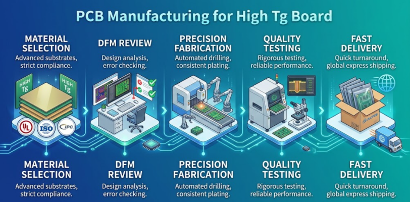
JLCPCB's SMT services are well compatible with the lead-free reflow profile that high-Tg boards are designed for, so that the material advantage can be kept during the assembly process. Stencils cost from $6, and the turnkey assembly model makes the entire process from bare board to tested assembly easy.
FAQ about High Tg FR4
Q: What is high Tg FR4?
High Tg FR4 is a variant of the standard FR4 fiberglass-reinforced epoxy laminate with a glass transition temperature of 170 degrees Celsius or higher, compared to 130-140 degrees Celsius for standard FR4. It offers improved thermal stability, lower Z-axis expansion, and better resistance to delamination at elevated temperatures.
Q: Why use high Tg FR4 instead of standard FR4?
High Tg FR4 is the preferred choice when your PCB will be exposed to high temperatures during lead-free reflow soldering (peak temperatures of 245-260 C) or during operation in harsh environments. It reduces the risk of via barrel cracking, board warpage, and delamination, which standard FR4 is more susceptible to under these conditions.
Q: Is high Tg FR4 more expensive than standard FR4?
Yes, high Tg FR4 typically costs 10-20% more than standard FR4 due to the more advanced resin chemistry. However, this cost increase is generally minor compared to the total board cost and is far outweighed by the reliability benefits, especially for multilayer boards and products destined for automotive, industrial, or military applications.
Q: What Tg value should I specify for lead-free assembly?
For boards going through lead-free reflow with SAC305 solder, a minimum Tg of 150 degrees Celsius is recommended. For multilayer boards (6+ layers) or boards that will undergo multiple reflow cycles (double-sided SMT assembly), specifying Tg of 170 degrees Celsius or higher provides a more comfortable safety margin.
Conclusion
The selection of the appropriate PCB substrate material is an important decision that can be made at the beginning of a design process, and high Tg FR4 has proven to be the standard material for all applications requiring long-term reliability requirements, high operating temperatures, or lead-free assembly. The slightly higher cost of 10-20% is amply repaid by the fewer manufacturing defects, field failure rates, and fewer warranty headaches.
With the ever-increasing use of electronics in more extreme environments and at ever-increasing power densities, the choices of materials become more critical. By knowing the link between Tg, CTE, and thermal reliability, you can make an educated decision instead of a guess. When you are ready to apply these principles, JLCPCB's high Tg FR4 capabilities, plus DFM support and fast production, will help you to get reliable high-temperature PCBs from prototype to volume production.
Keep Learning
Choosing the Right PCB Solder Mask Material for Reliable PCBs
Key Takeaways Dual-Curing: UV defines openings; heat cures epoxy for durability. LPI vs. Coverlay: LPI for rigid boards; coverlay for flexible circuits. Color & Pitch: Green allows tighter dams (0.10 mm) than black/white (0.13 mm). Protection: Prevents solder bridges and seals copper from moisture. Cure Quality: Proper baking prevents mask peeling during plating and reflow. PCB solder mask material is a cured polymer film usually 10 to 30 µm (0.4 to 1.2 mil) thick. During reflow, it is the only barrie......
Safeguarding Circuit Boards Against Breakdown Voltage Failure
Key Takeaways Construction Matters: Breakdown voltage depends on stackup and defects, not raw material ratings. Stress Causes Failures: Heat and moisture degrade insulation over time, leading to field defects. Four Main Failure Modes: Insulation fails via internal voids, treeing, CAF growth, or surface tracking. Layout Design Fixes: Use dual prepregs, wider hole spacing, rounded trace corners, and isolation slots. Testing Split: Bare-board testing checks low-voltage net continuity, while hi-pot tests ......
Is FR4 the Best Board Material for Your Design
Key Takeaways Best All-Rounder: Ideal balance of strength, insulation, and low cost for standard PCBs. Clear Limits: Poor heat dissipation (~0.3 W/m·K) and high loss for RF (>3 GHz). Alternatives: Use Rogers for RF, Aluminum for high heat, and FPC for flexibility. Selection Essentials: Pick High-Tg (170°C+) for lead-free reflow and custom stackups for impedance. JLCPCB Advantage: 1–32 layer FR4 boards with ±10% impedance control and 24h fast dispatch. In the world of electronics and printed circuit bo......
Optimizing High-Voltage Circuit Safety with PCB Dielectric Strength
Key Takeaways Non-linear Scaling: Dielectric strength drops as thickness increases. Safety vs Signals: Dielectric strength ensures safety, while Dk controls signal speed. Material Selection: High-voltage safety depends on Tg, CTI, and moisture resistance. Spacing Rules: Clearance prevents air arcs, while creepage prevents surface tracking. Assembly Testing: Hi-pot testing requires finished assemblies, not bare boards. Dielectric strength is the number engineers quote to prove a board is safe at mains ......
How Copper Foil Shapes PCB Performance and Manufacturing Quality
Key Takeaways Weight: 1 oz copper ≈ 35 µm thickness; higher weight increases current capacity. Types: ED for standard rigid boards, RA for dynamic flex circuits. DFM & Loss: Smoother foil lowers RF loss; thicker foil requires wider trace spacing. The part of a PCB that actually carries the electrical signal is the copper foil. The strength comes from the glass weave, the resin is used to keep the layers together, and the solder mask is used to provide protection and separation of exposed copper. But w......
Why PCB Substrate Choice Matters More Than You Think
Key Takeaways Prevents Via Failures: Z-axis CTE expansion strains via barrels; right substrates prevent field failure. Specify Beyond FR-4: Name IPC-4101 sheets to guarantee proper Tg and lower thermal growth. Match Material to Need: Choose FR-4 for standard, Polyimide for flex, Aluminum for heat, and Rogers for >3 GHz. Use Real Fab Stackups: Prepreg weave alters Dk; compute impedance using real factory stackups. The PCB substrate is the one part of your board you never actually draw. You choose a thi......