What Are the Main Relay Types and Which One Should You Use?
17 min
- Relay Types at a Glance: Comparison Chart
- Electromechanical Relay vs. Solid-State Relay
- What Is a Relay and How Are Relay Types Classified?
- Electromechanical Relay Types
- Latching and Polarized Relay Types
- Solid-State Relay Types
- Relay Contact Forms: SPST, SPDT, DPDT, and Form A, B, C
- How to Choose the Right Relay Type for Your Load
- FAQs About Relay Types
Key Takeaways
- Two Main Types: Relays fall into two main categories: electromechanical relays, which use moving metal contacts to switch a circuit, and solid-state relays, which use electronic components with no moving parts.
- Choose Based on the Load: The load type determines which relay you need. Consider whether the load uses AC or DC, how much current it draws during normal operation and startup, and how frequently it needs to switch.
- Coil Behavior: A monostable relay returns to rest when its coil is de-energized, while a latching relay holds its last state without coil current, which suits battery-powered designs.
- Understanding Contact Types: SPST, SPDT, and DPDT describe how many circuits a relay can control and how its contacts switch between connections. Form A contacts are normally open (NO), Form B contacts are normally closed (NC), and Form C contacts switch between NO and NC.
At their core, relays fall into two main categories: electromechanical relays (EMRs), which use physical moving contacts to switch circuits, and solid-state relays (SSRs), which rely on semiconductor devices with no moving parts.
Each type has different characteristics, including load ratings, switching behavior, contact configurations, and applications.
Selecting the correct relay depends entirely on your specific load requirements. For example, a relay rated for an AC heating element will likely fail when driving a DC motor or handling sensitive sensor signals.
In this guide, you will learn:
- The standard relay types, compared in one chart with example parts
- When to use an electromechanical relay and when to use a solid-state relay
- How to read SPST, SPDT, DPDT, and Form A, B, and C contact forms
- How to choose the right relay type for your PCB
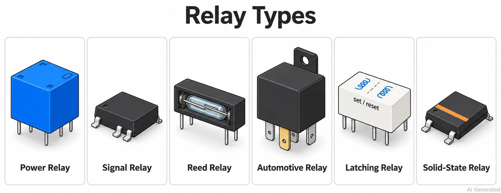
Figure: Common relay types
Relay Types at a Glance: Comparison Chart
The chart compares 14 standard relay types by switching element, typical rating, and best-fit load, and links an example JLCPCB part for each.
| Relay Type | Switches With | Typical Rating | Best For | Example Part |
|---|---|---|---|---|
| General-purpose power relay | Moving contacts | 5 to 10 A at 250 VAC | Mains loads on control boards and modules | SRD-05VDC-SL-C (C35449) |
| High-current PCB power relay | Moving contacts | 30 A at 240 VAC | Heaters, chargers, and inverters | HF105F-1/005D-1HST (C2976768) |
| Signal relay | Small moving contacts | 1 A at 30 VDC | Audio, test, and communication signals | G6K-2F-Y-TR DC5 (C47190) |
| Reed relay | A reed switch in a glass capsule | 0.5 A at 200 VDC | Fast, low-level switching and test equipment | S1A050000 (C150532) |
| Latching relay | Contacts that hold without coil current | 1 A to 50 A | Battery devices and energy meters | TQ2-L2-5V (C1525303) |
| Polarized relay | Contacts with a permanent magnet | Signal-level loads | Sensitive, low-power signal switching | HFD4/5-SR (C64399) |
| Automotive relay | Moving contacts | 15 A at 14 VDC | 12 V vehicle loads | CMA51H-S-DC12V-C (C125689) |
| Plug-in industrial relay | Moving contacts in a socket | Control-panel loads | Panels that need field replacement | MY2N-GS-R DC24 (C51823247) |
| Force-guided safety relay | Mechanically linked contacts | 6 A at 250 VAC | Safety circuits and machine guarding | G7SA-2A2B DC24 (C397126) |
| MOSFET-output SSR | Back-to-back MOSFETs | 0.5 A at 60 V | Silent AC or DC signal switching | AQY282SX (C250827) |
| Triac-output SSR | Triac | 0.9 A at 110/220 VAC | Small AC loads | BC2213 (C596508) |
| Panel-mount SSR | Power semiconductor on a heat sink | 25 A to 50 A class | Heaters and furnaces | D2450S (C54196256) |
| Time-delay relay | Timer plus contacts | Control-panel loads | Delayed switching in panels | See the Time relay category |
| Contactor | Large contacts with arc control | 100 A at 900 VDC | Motors and battery power circuits | LEV100A5ANG (C1519173) |
Electromechanical Relay vs. Solid-State Relay
Choose an electromechanical relay (EMR) when you need low power loss, complete disconnection when switched off, or the flexibility to switch both AC and DC loads with the same relay, provided its contacts are properly rated.
Choose a solid-state relay (SSR) when you need fast, silent, or frequent switching without the wear and tear of mechanical contacts.
In short, an EMR conducts with very little loss, but its contacts wear, while an SSR switches without wear but drops voltage and leaks a small current.
| Property | Electromechanical Relay | Solid-State Relay | Why It Matters |
|---|---|---|---|
| Switching element | Metal contacts moved by a coil | MOSFET, triac, or thyristor output | Sets loss, leakage, and life |
| Switching speed | Milliseconds: 3 ms max (G6K) to 10 ms max (SRD) | Microseconds for random turn-on; up to a half cycle for zero-cross | Sets the fastest control rate |
| Life | Limited by contact wear: 100,000 operations at rated load (SRD) | No contact wear | Frequent switching favors an SSR |
| On-state loss | Contact resistance: 100 mΩ max (SRD) | 0.85 Ω typical (AQY282S) or up to 2.3 V drop (BC2213) | An SSR needs heat sinking at higher current |
| Off-state | Open an air gap | Leakage current: 100 µA max (BC2213) | Leakage can keep a small load partly on |
| AC and DC | Both, with separate ratings | MOSFET output for AC or DC; triac output for AC only | A triac SSR cannot turn off a DC load |
| Noise | Audible click and contact arcing | Silent switching | Matters in audio and quiet products |
| Typical failure | Contacts weld closed or wear open | Output commonly fails short | Plan protection for the failure state |
- Choose an EMR for: mains and DC power loads that switch a few times per hour, mixed AC and DC switching, and loads that must be fully disconnected when off.
- Choose an SSR for: heaters and loads that switch many times per minute, silent products, and equipment exposed to vibration.
What Is a Relay and How Are Relay Types Classified?
A relay is an electrically operated switch. A small control signal on its input switches a separate, electrically isolated load circuit, so a 5 V logic circuit can control a mains or high-current load.
In an EMR, a coil moves an armature that opens or closes metal contacts. In an SSR, an input LED drives a photosensitive semiconductor output. For the schematic drawings of each type, see the relay symbol guide.
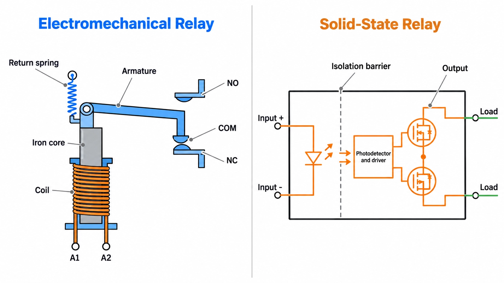
Figure: Electromechanical relay cutaway and solid-state relay block diagram.
Relay types are classified along four axes:
- Switching principle: electromechanical contacts or a solid-state output.
- Coil behavior: monostable, latching, or polarized.
- Contact form: the number of poles and throws, and whether each contact is normally open or normally closed.
- Application: the load the relay is built for, such as signal, power, automotive, safety, or industrial control.
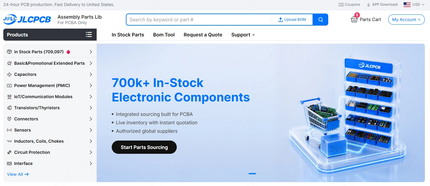
The relay examples referenced in this guide are available as Extended Parts in the JLCPCB Parts Library. Check stock availability and the part classification when building your BOM.
The main relay types are organized into dedicated categories under the Relays hub for electromechanical relays and under Optoisolators for solid-state relays:
With PCB assembly, you can order your PCB and selected relays together, while checking each component's package and footprint before finalizing the BOM.
Electromechanical Relay Types
Electromechanical relays share the same coil-and-contact principle and differ in contact ratings, size, sealing, and mounting. The seven types below are general-purpose power, high-current power, signal, reed, automotive, plug-in industrial, and force-guided safety relays.
1. General-Purpose Power Relay
A general-purpose power relay switches mains-level loads up to about 10 A from a small DC coil. It is the cube-shaped relay found on many relay modules and appliance control boards.
Most are SPDT (Form C): the common terminal connects to the normally closed contact at rest and transfers to the normally open contact when the coil is energized.
JLCPCB Parts examples:
- SRD-05VDC-SL-C (C35449): a 5 V SPDT relay rated 10 A at 250 VAC in its datasheet
- SRD-12VDC-SL-C (C30431): its 12 V version
- G5NB-1A-E-DC5V (C48746): a slim SPST-NO relay rated 5 A at 250 VAC
2. High-Current PCB Power Relay
A high-current PCB power relay carries 20-40 A through PCB-mounted terminals. It can switch heaters, EV chargers, and inverter outputs without a separate contactor. Its DC rating is lower than its AC rating, because DC has no zero crossing to extinguish the contact arc.
JLCPCB Parts examples:
- HF105F-1/005D-1HST (C2976768): a 5 V SPST-NO relay with a coil of approximately 900 mW
3. Signal Relay
A signal relay switches low-level signals up to about 1 A or 2 A in a small DIP or SMD package. Its contacts are often gold-clad to maintain stable contact resistance at low current.
Signal relays are well-suited for audio routing, test fixtures, telecom lines, and measurement-range switching. Many are DPDT, so one coil switches two independent channels.
JLCPCB Parts examples:
- G6K-2F-Y-TR DC5 (C47190): an SMD DPDT relay rated 1 A at 30 VDC
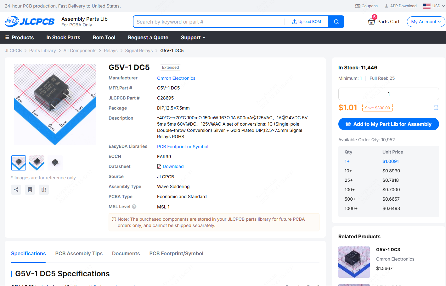
- G5V-1 DC5 (C28695): a DIP SPDT relay rated 1 A at 24 VDC with a 150 mW coil
4. Reed Relay
A reed relay uses two ferromagnetic reeds sealed in a glass capsule. The coil around the capsule magnetizes the reeds, causing them to close, and their small moving mass makes the relay operate faster than an armature-type relay.
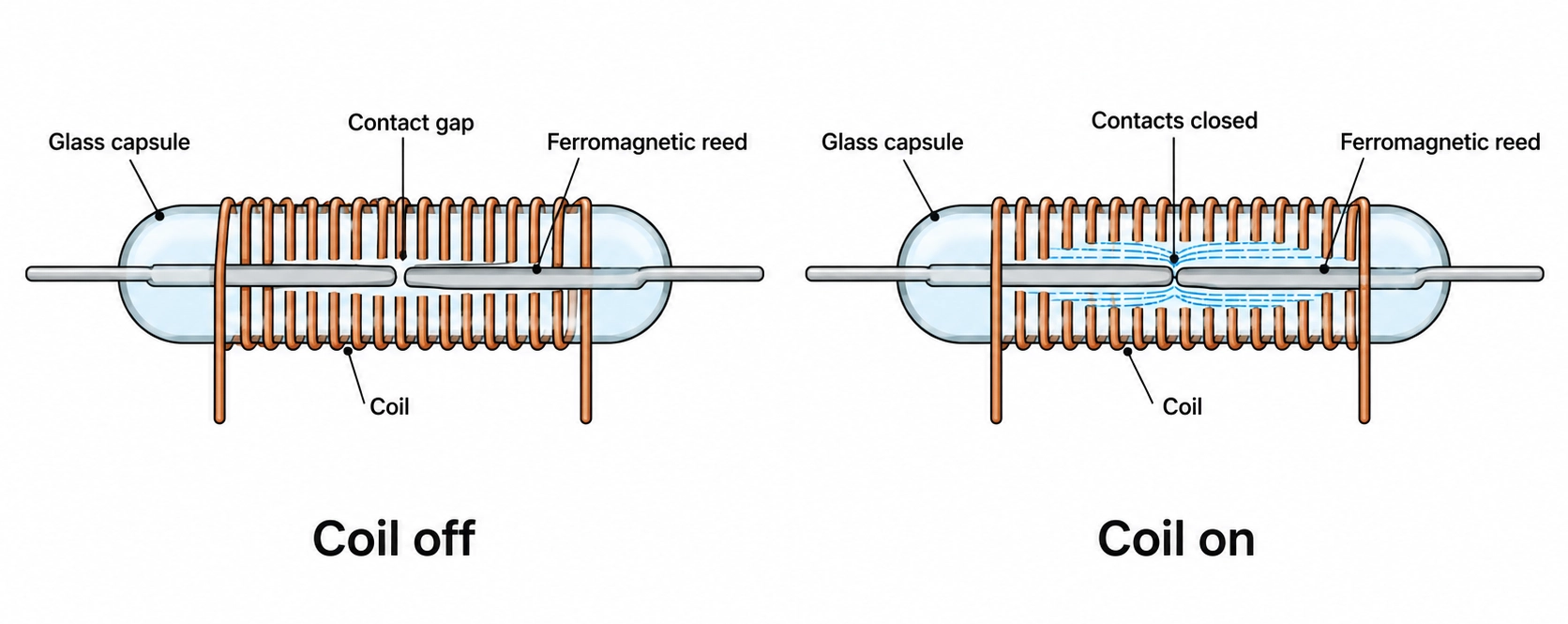
Figure: Reed relay with two ferromagnetic reeds sealed in a glass capsule inside the coil.
The S1A050000 operates at a maximum of 0.5 ms and is rated for 5 × 10⁷ operations at the signal level. Its current limit is current-limited: it switches at a maximum of 0.5 A, and capacitive inrush can weld the reeds, so add series resistance when the load is capacitive.
JLCPCB Parts examples:
- S1A050000 (C150532): a 5 V SPST-NO reed relay with a 10 mA coil
- SIP-HV1A05 (C22388647): a high-voltage reed relay that switches up to 1.5 kVDC
5. Automotive Relay
An automotive relay switches DC loads in a vehicle, such as fans, lamps, and pumps, most often on 12 V systems. It is rated for DC at vehicle-system voltage, for high inrush current, and for vehicle temperature and vibration. Its contact ratings are given at 14 VDC or 16 VDC, so they do not cover AC mains loads.
JLCPCB Parts examples:
- CMA51H-S-DC12V-C (C125689): a 12 V SPDT relay rated 15 A at 14 VDC with a 60 A maximum inrush current
- BARK-S-112D (C22385002): a 12 V SPDT relay rated 30 A at 16 VDC
6. Plug-In Industrial Relay and Socket
A plug-in industrial relay mounts in a DIN-rail or panel socket, so it can be replaced without rewiring the circuit. Many include an LED indicator, which the "N" in MY2N denotes. These relays typically run from a 24 VDC or mains control supply. They switch control-panel loads such as solenoids, indicator lamps, and contactor coils.
JLCPCB Parts examples:
- MY2N-GS-R DC24 (C51823247): a 24 VDC DPDT plug-in relay
- 14FF-2Z-A1 (C22456423): a two-pole relay socket
Confirm the socket pinout against the relay datasheet before ordering the pair.
7. Force-Guided Safety Relay
A force-guided safety relay mechanically links its normally open and normally closed contacts, preventing them from closing simultaneously. If a normally open contact welds, the linked normally closed contact remains open, allowing the monitoring circuit to detect the fault. This design is used in emergency-stop circuits, machine guarding, and safety controllers.
JLCPCB Parts examples:
- G7SA-2A2B DC24 (C397126): a 24 VDC relay with two normally open and two normally closed contacts, rated 6 A at 250 VAC
Latching and Polarized Relay Types
Latching and polarized relays are electromechanical relays defined by how the coil sets and holds the contacts, rather than by load rating. Choose them when coil power or coil polarity matters.
Monostable vs. Latching Relay
A standard monostable relay has a single stable state: it maintains its switched position only while power is applied to the coil, returning to rest the moment power is removed.
The difference shows up in the power budget: An SRD-05VDC-SL-C coil draws about 70 mA at 5 V while the relay is on, whereas a latching relay requires only a short pulse to change state. A latching relay retains its last set state during a power loss, but shock or vibration during shipping can change it, so firmware should drive it to a known state at startup.
Single-Coil vs. Dual-Coil Latching Relay
A single-coil latching relay sets and resets by reversing the polarity of one coil, which needs an H-bridge or another bidirectional drive. A dual-coil latching relay has separate set and reset coils, each of which can be driven by a single low-side switch.
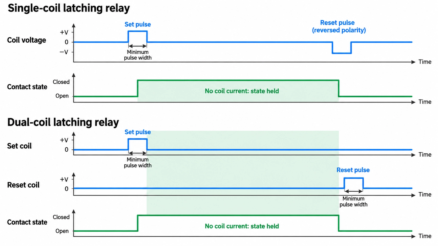
Figure: Set and reset pulse timing for single-coil and dual-coil latching relays.
The pulse must be long enough to complete the transfer. Omron specifies at least 10 ms for the G6KU, and Hongfa specifies at least 50 ms for the HFE10.
JLCPCB examples:
- G6KU-2F-Y-TR DC5 (C2153173): a single-coil SMD DPDT relay
- TQ2-L2-5V (C1525303): a dual-coil DPDT signal relay
- HFE10-2/12-HT-L2 (C2892810): a 12 V dual-coil power latching relay with 50 A switching capacity, a type commonly used in energy meters
Polarized Relay
A polarized relay adds a permanent magnet to its magnetic circuit, so it operates only when the coil voltage has the correct polarity. The magnet assists the coil, thereby reducing the power required to switch. A reversed coil connection prevents a polarized relay from operating correctly, so check the coil "+" pin on the footprint.
JLCPCB example:
- HFD4/5-SR (C64399): a 5 V single-side-stable polarized SMD signal relay with two changeover contacts
Solid-State Relay Types
Solid-state relays are grouped by their output device because the output decides whether the relay can switch AC, DC, or both. Each type uses an input LED that is optically isolated from the output, similar to an optocoupler.
MOSFET-Output Solid-State Relay
A MOSFET-output SSR, often called a PhotoMOS relay, uses two back-to-back MOSFETs driven by a photovoltaic diode array. Because the MOSFET pair blocks in both directions, it switches AC or DC loads. These relays replace signal relays where speed, silence, or long life matters, but their on-resistance limits the load current.
JLCPCB examples:
- AQY282SX (C250827): 60 V and 0.5 A with 0.85 Ω typical on-resistance
- TLP172GM (C261926): 350 V and 110 mA
- CPC1017NTR (C81521): 60 V and 100 mA
Triac-Output Solid-State Relay: Zero-Cross vs. Random Turn-On
A triac-output SSR switches AC loads only. Once the triac conducts, it stays on until the load current falls below its holding current, which happens at each AC zero crossing but not on a DC supply.
Zero-cross versions turn on near the zero-voltage point, which reduces inrush current and EMI on resistive loads. Random turn-on versions switch as soon as the input is driven, which phase-angle control requires.
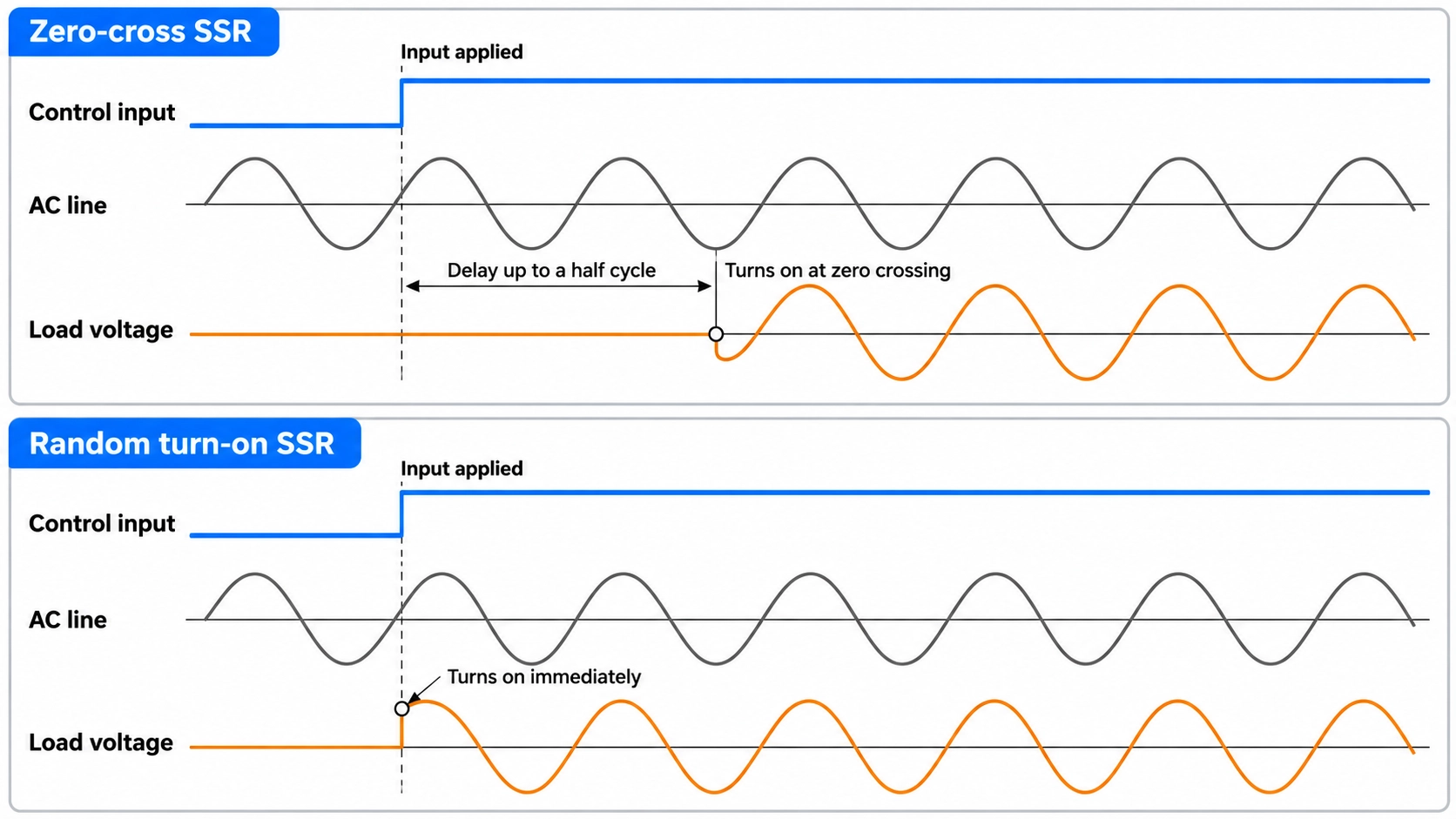
Figure: Zero-cross and random turn-on SSR switching points on an AC load-voltage waveform.
JLCPCB examples:
Note
The KMOC3063S (C2890340) appears among solid-state relays in some part listings, but it is a zero-cross triac driver. Its output is designed to trigger an external power triac, not to switch the load directly.
Panel-Mount Solid-State Relay
A panel-mount SSR switches tens of amps through screw terminals and mounts on a heat sink. Its output has an on-state voltage drop, so it dissipates heat roughly in proportion to load current.
JLCPCB examples:
- D2450S (C54196256): a 50 A-class AC panel SSR
- SSR-25DA (C52146207): a 25 A-class DC-input, AC-output panel SSR
Relay Contact Forms: SPST, SPDT, DPDT, and Form A, B, C
The contact form describes how many circuits a relay switches and the state of each contact at rest. Poles are independent circuits, throws are the positions each pole can connect to, and the Form letter names the arrangement.
| Contact Form | Poles and Throws | Form Code | State at Rest | Example Part |
|---|---|---|---|---|
| SPST-NO | 1 pole, 1 throw | Form A | Open | G5NB-1A-E-DC5V |
| SPST-NC | 1 pole, 1 throw | Form B | Closed | Offered as a variant in power relay families such as the HF105F-1 |
| SPDT | 1 pole, 2 throws | Form C | COM connected to NC | SRD-05VDC-SL-C |
| DPDT | 2 poles, 2 throws each | 2 Form C | Both COMs are connected to the NC | G6K-2F-Y-TR DC5 |
| 2NO + 2NC | 4 poles, 1 throw each | 2 Form A + 2 Form B | NO open, NC closed | G7SA-2A2B DC24 |
| SPST-NO, double make | 1 pole, 2 contact gaps in series | Form X | Open | LEV100A5ANG |
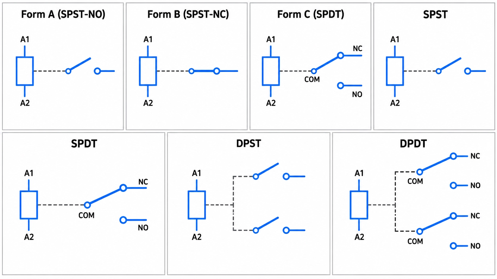
Figure: Form A, Form B, Form C, SPST, SPDT, DPST, and DPDT relays.
- Choose Form A when the load should be off if the coil loses power.
- Choose Form B when the load should stay on if the coil loses power.
- Choose Form C when one coil must select between two circuits.
For how each form is drawn on a schematic, see the switch symbol guide.
How to Choose the Right Relay Type for Your Load
Choose a relay type by working from the load back to the coil: start with the load's voltage, current, and switching rate, then check the drive circuit, power budget, safety needs, and package.
- Use an electromechanical relay for low-loss AC or DC power switching, with a fully open circuit when off
- Use a solid-state relay for fast, silent, or frequent switching.
Then narrow the choice by load rating, coil behavior, and contact form. Matching the relay type to the load helps prevent contact welding, excess heat, and unexpected leakage.
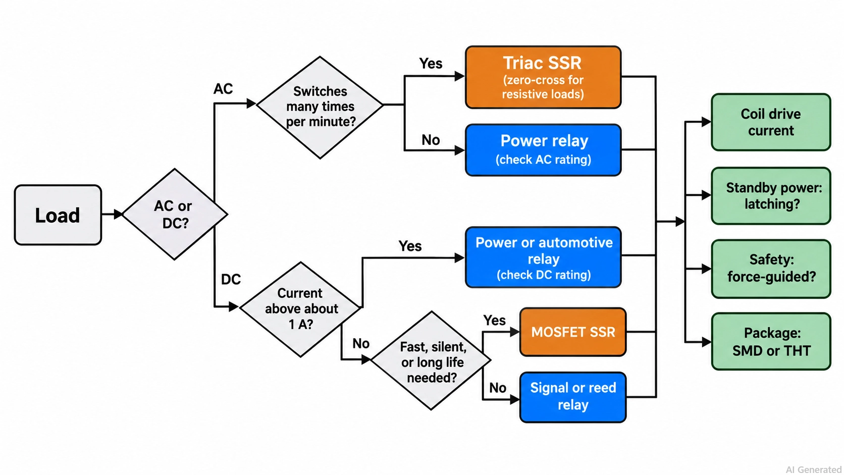
Figure: Relay type selection flowchart from load type
FAQs About Relay Types
What Are the Main Types of Relays?
The two main types are electromechanical relays and solid-state relays. Common subtypes include power, signal, reed, latching, automotive, safety, and MOSFET- or triac-output solid-state relays.
What Is the Most Common Type of Relay?
The general-purpose electromechanical power relay with an SPDT contact is one of the most common. It switches mains loads up to about 10 A from a 5 V, 12 V, or 24 V coil.
Can a Solid-State Relay Switch DC?
Yes, if it has a MOSFET or transistor output. A triac-output SSR cannot turn off a DC load, because the triac stays on until the current falls below its holding current.
What Is the Difference Between a Relay and a Contactor?
A contactor is a relay built for high-power loads such as motors. It has larger contacts and arc control, while a relay usually switches lower currents and control signals.
What Does 5VDC Mean on a Relay?
It is the rated coil voltage, the DC voltage that energizes the coil. The contact rating is listed separately, for example, 10 A at 250 VAC.
Popular Articles
• SMD Resistor Package Sizes: Complete Size Chart, Footprints & How to Choose
• How to Solder SMD Components Like a Pro [2026 Updated]
• SMD Resistor Codes: How to Read 3-Digit, 4-Digit, and EIA-96 Markings
• SMD Capacitor Codes: Identification, Markings, and Polarity
• SMD Capacitor Sizes: Complete Size Chart and Selection Tips for PCB Design and Assembly
Keep Learning
What Are the Main Relay Types and Which One Should You Use?
Key Takeaways Two Main Types: Relays fall into two main categories: electromechanical relays, which use moving metal contacts to switch a circuit, and solid-state relays, which use electronic components with no moving parts. Choose Based on the Load: The load type determines which relay you need. Consider whether the load uses AC or DC, how much current it draws during normal operation and startup, and how frequently it needs to switch. Coil Behavior: A monostable relay returns to rest when its coil i......
SMD MOSFET Code Guide: How to Identify, Test and Replace a MOSFET
Figure: AO3400A (C20917) in the JLCPCB parts library. The listing gives RDS(on) at 2.5 V gate drive, the number that matters in the replacement example later in this guide. An SMD MOSFET code is the two or three characters printed on top of the package, and on its own it rarely tells you which part you're holding. SMD resistors follow standard marking schemes, such as three- and four-digit codes and EIA-96. MOSFETs don't. The same short code can appear on unrelated parts from different manufacturers, ......
ESP8266 vs ESP32: Which One Should You Use?
Key Takeaways ESP32: Dual-core 240 MHz CPU, Bluetooth Classic and BLE, 520 KB SRAM, and up to 34 GPIOs. ESP8266: Single-core CPU, no Bluetooth, and around 50 KB of free RAM for applications. Lifecycle status: Espressif marks the ESP8266 Not Recommended for New Designs (NRND) and names the ESP32-C2 (ESP8684) as its upgrade, although the ESP8266 remains in production with a longevity commitment. Which ESP32 to use: Choose the ESP32-C2 for simple Wi-Fi or Bluetooth LE firmware, the ESP32-C3 for more memo......
What Is a Thermistor? A Practical Guide to NTC, PTC, Applications, and Circuit Design
Key Takeaways Definition: A thermistor is a thermally sensitive resistor whose resistance changes markedly and predictably with temperature, typically by about 4.4% per °C for a standard 10 kΩ NTC (B25/50 = 3950 K) near 25 °C. NTC vs. PTC: An NTC thermistor's resistance falls as temperature rises, which suits temperature sensing and inrush current limiting; a switching PTC's resistance rises steeply above its switch temperature, which suits circuit protection. Key Specifications: An NTC thermistor is ......
What Is the ESP32-CAM, and How to Wire, Power, and Program It?
Key Takeaways Board, not chip: The ESP32-CAM is an AI-Thinker development board, not an Espressif product. It carries AI-Thinker's ESP32-S module, an OV2640 camera, PSRAM, a microSD slot, and a flash LED. No USB port: The board has no USB connector or USB-to-UART bridge, so you program it via its serial pins using a 3.3 V USB-to-serial adapter, with GPIO0 held low at reset. Few free pins: The camera, PSRAM, and microSD card occupy most GPIOs. With the microSD card unused, GPIO2, GPIO4, GPIO12, GPIO13,......
ESP32 Versions: Which One Should You Use for Your Project?
Key Takeaways Radios decide first: ESP32 versions differ mainly in their radios, CPU cores, and peripherals. Common defaults: The ESP32-C3 suits low-cost Wi-Fi and Bluetooth LE, the ESP32-S3 suits camera, display, voice, and on-device AI. Original ESP32: The chip is still in production and remains the choice for Bluetooth Classic. Versions without Wi-Fi: The ESP32-H2 targets battery-powered Thread and Zigbee devices. Chip, module, or board: Prototype on a development board, then design a module onto y......