
Switch Symbol Guide: Meaning, Types & Circuit Diagram Examples and Real Applications
10 min
- Types of Switches and Their Symbols
- What Is a Switch Symbol?
- Key Concepts of Switch Symbols: Open vs Closed States
- Switch Symbols in Real Circuit Examples
- How to Identify a Switch Symbol in Schematics
- Common Mistakes When Reading Switch Symbols
- From Schematic to PCB: Using Switch Symbols in PCB Design
- FAQs About Switch Symbol
- Conclusion
Think of a switch as a drawbridge in your electronic circuit. When the bridge is down, traffic (current) flows freely. When the bridge is up, the path is broken, and everything stops.
By understanding the electrical switch symbol explained on paper, you can quickly identify how a device turns on, routes signals, or triggers actions. Learning these fundamental symbols makes circuit troubleshooting fast and intuitive.
What you will learn in this guide:
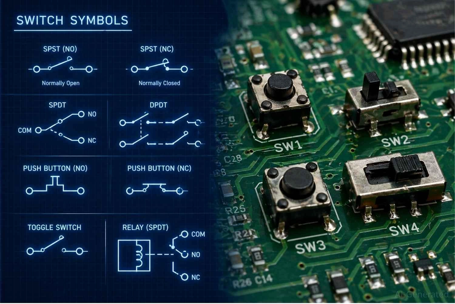
Figure: The transition from schematic switch symbols to real physical switch components mounted on a PCB.
Types of Switches and Their Symbols
The most common types of switch symbols used in circuit diagrams include:
- SPST Switch Symbol (Single Pole Single Throw): The simplest ON/OFF control.
- SPDT Switch Symbol (Single Pole Double Throw): Selects between two distinct circuit paths.
- DPDT Switch Symbol (Double Pole Double Throw): Controls two separate circuits simultaneously.
- Push Button Switch Symbol (NO / NC): Momentary action for user input.
- Toggle Switch Symbol: Maintained mechanical lever switching.
- Rotary Switch Symbol: Multi-position mode or channel selection.
- Relay Switch Symbol (Electromechanical): Controlled electrically for high-power switching.
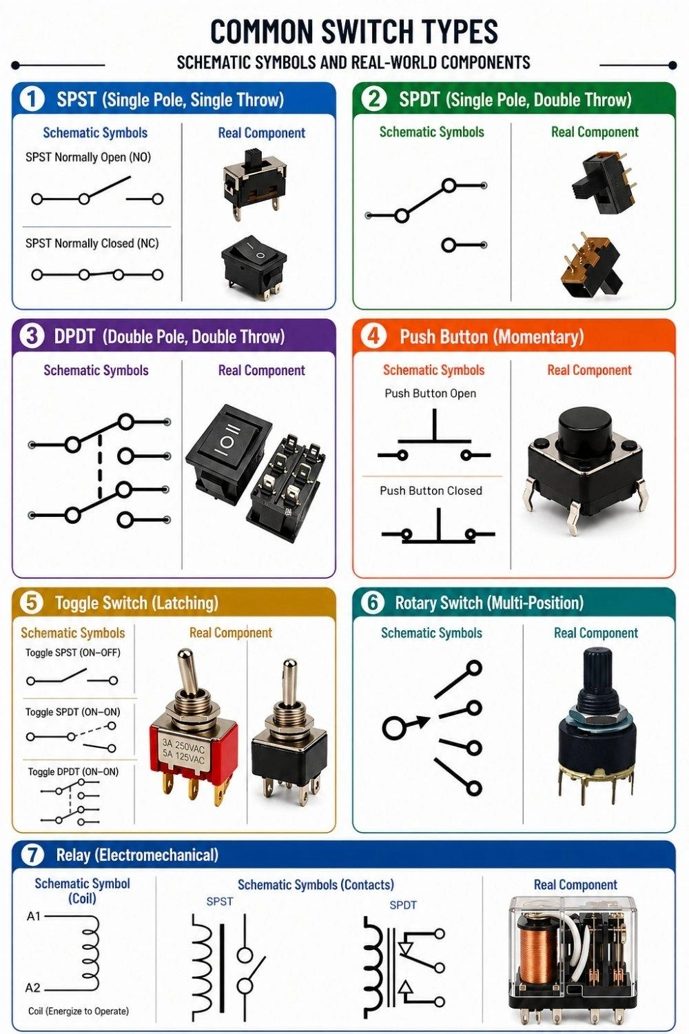
| Switch Type | Schematic Symbol | Primary Function |
|---|---|---|
| SPST | Two terminals with a single breaking lever. | Basic ON/OFF control. |
| SPDT | One common terminal connecting to one of two outputs. | Selecting between two distinct circuit paths. |
| DPDT | Two SPDT symbols linked by a dashed line. | Controlling two separate circuits simultaneously. |
| Push Button | T-shaped plunger hovering above or across terminals. | Momentary user input (NO or NC). |
| Toggle | Lever breaking a circuit, often identical to SPST/SPDT. | Maintained mechanical switching. |
| Rotary | A central pole pointing to a circular array of terminals. | Multi-position mode or channel selection. |
| Relay | An electromagnetic coil box linked to switch contacts. | Electrically controlled, high-power switching. |
SPST Switch Symbol (Single Pole Single Throw)
The simplest switch symbol to read. It has one input, one output, and functions solely as a straightforward ON or OFF gate.
SPDT Switch Symbol (Single Pole Double Throw)
This symbol features one common input that toggles between two separate outputs. It is perfect for routing a signal or toggling between two different LEDs.
DPDT Switch Symbol (Double Pole Double Throw)
A SPDT vs DPDT switch symbol diagram highlights that a DPDT is simply two separate SPDT switches moved by the same mechanical actuator (indicated by a dashed connecting line).
Push Button Switch Symbol (NO / NC)
Drawn with a flat plunger above two terminals, this dictates momentary action. It only changes state as long as a user is actively pressing it.
Toggle Switch Symbol
Often visually similar to a standard SPST, the toggle switch symbol vs push button distinction lies in its maintained action. Once flipped, it stays in that position.
Rotary Switch Symbol
Represented as a single input line that can pivot to touch one of many output terminals, ideal for multi-position mode selection.
Electromechanical Relay Symbol
Comparing a relay switch symbol vs manual switch, the relay includes an inductor coil box. Applying power to the coil creates a magnetic field that physically pulls the switch contacts closed.
What Is a Switch Symbol?
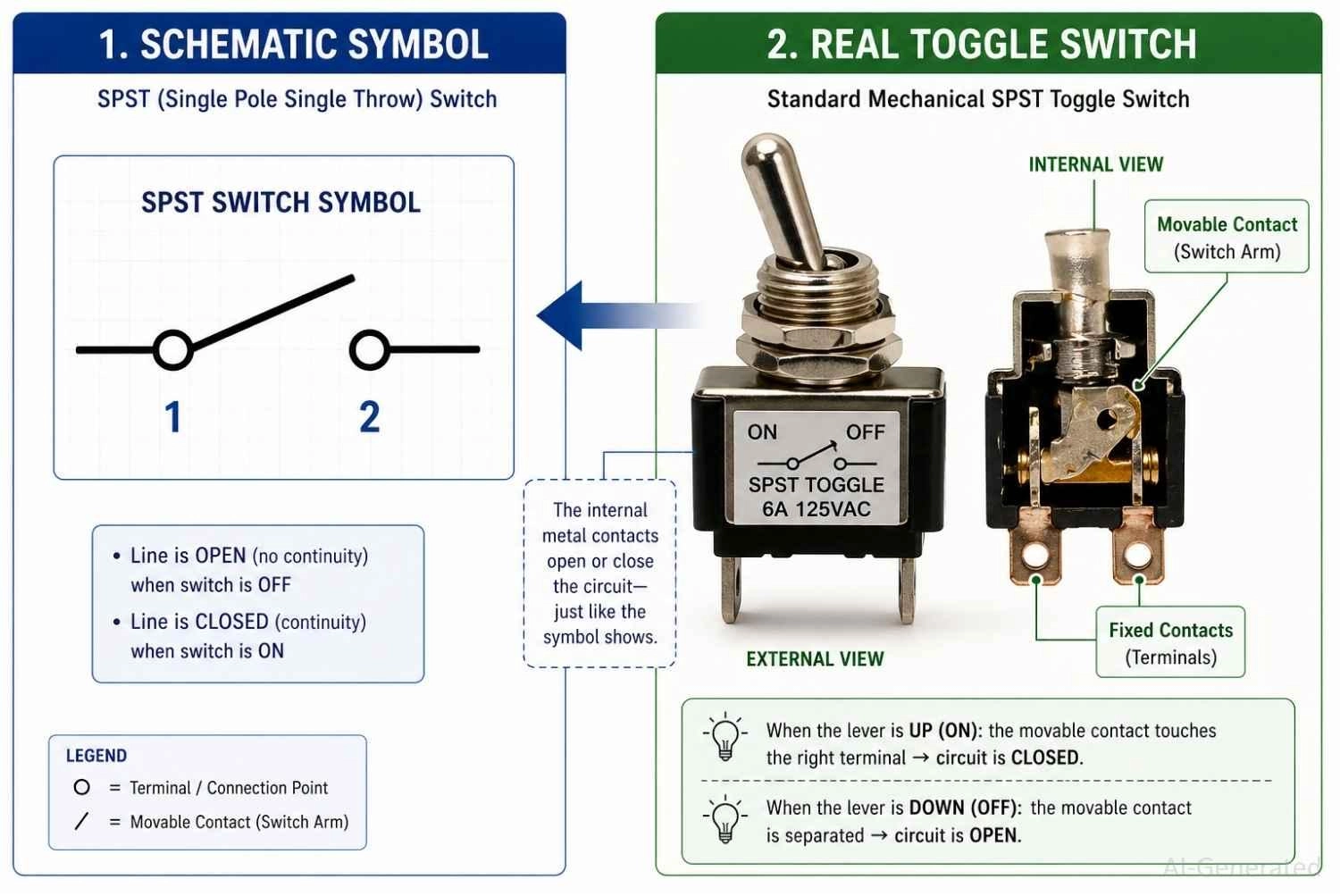
Figure: Demonstrating how a basic switch symbol represents the physical mechanical contacts inside a real toggle switch.
A switch symbol in a circuit diagram represents a mechanical or electrical control element. It shows exactly where a circuit can be intentionally broken or connected.
Why Switch Symbols Are Used in Electrical Schematics
- Simplifies control representation: It replaces complex mechanical drawings with simple lines and circles.
- Shows circuit state: It instantly indicates whether a circuit defaults to active or inactive.
Where Switch Symbols Are Used
You will find these symbols everywhere. They control mains voltage in power systems, capture user actions via user input buttons, and direct data paths in signal routing.
Key Concepts of Switch Symbols: Open vs Closed States
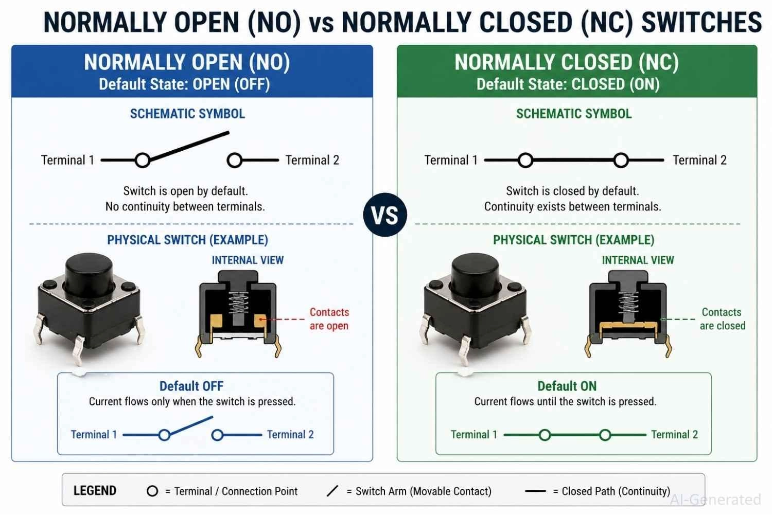
Figure: Diagram comparing Normally Open (NO) and Normally Closed (NC) switch symbol states.
Normally Open (NO) vs Normally Closed (NC)
The Normally Open (NO) and Normally Closed (NC) designations indicate a switch’s default state when no external force is applied.
An NO switch has an open circuit by default, while an NC switch has a closed circuit by default.
Open Circuit vs Closed Circuit Representation
A physical gap between the symbol's terminal circles represents a break in the circuit. A solid line connecting the terminals represents an unbroken, closed connection.
How Switch Position Controls Current Flow
Electricity requires a continuous loop. Current only flows when the schematic switch symbol is closed, allowing electrons to travel through the component and power your load.
When the switch is open, the circuit is interrupted, preventing current flow.
Switch Symbols in Real Circuit Examples
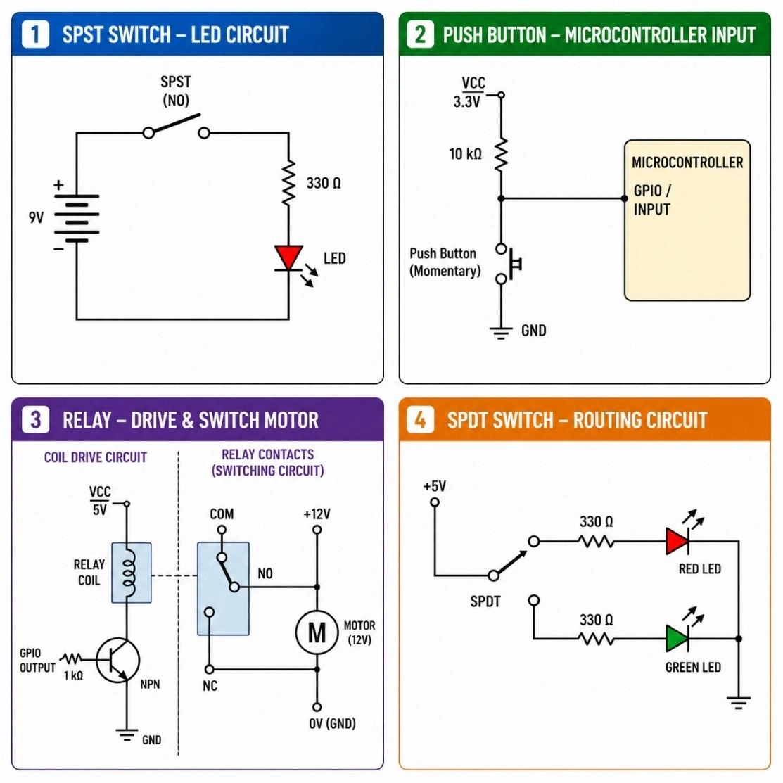
Figure: Circuit diagram examples showing an SPST LED circuit, a microcontroller push button, a motor relay, and an SPDT routing circuit.
Switch Controlling an LED Circuit
- Simple ON/OFF: An SPST switch placed in series between the battery and the LED.
- Interrupts power to turn the light completely off.
Push Button Input in Microcontroller Circuit
- Digital input: A normally open push button used to send a "HIGH" or "LOW" signal to a digital pin.
- Usually paired with a pull-up or pull-down resistor to prevent floating signals.
Relay Switch Controlling a Motor
- Indirect control: A tiny 5V signal powers the relay coil.
- The internal switch contacts then safely close to drive a heavy 120V or 240V motor.
Power Switching Circuit Example
- Mains control: Heavy-duty DPDT switches used to completely isolate both live and neutral lines.
- Ensures complete safety when an appliance is powered down.
How to Identify a Switch Symbol in Schematics
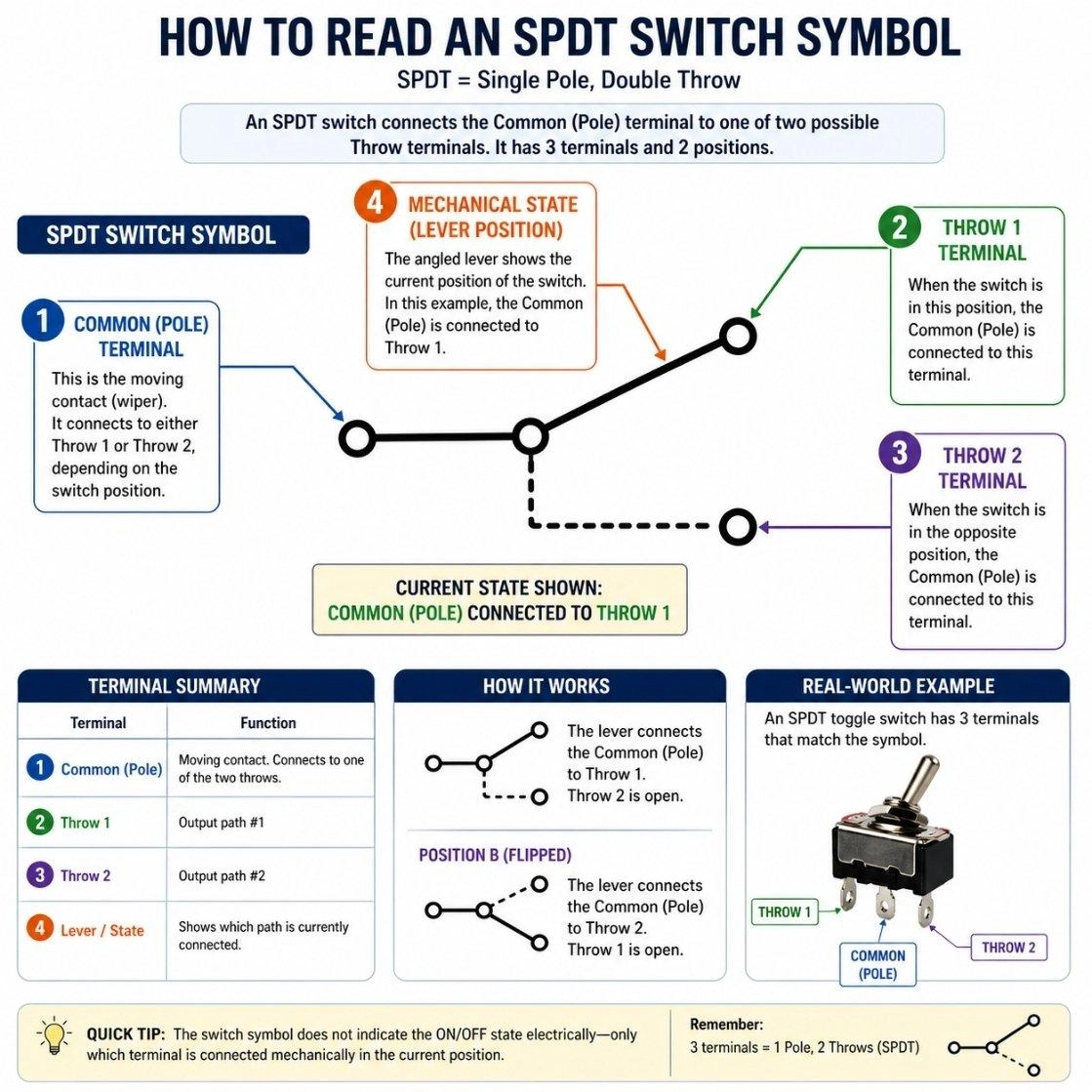
Figure: A step-by-step visual guide on how to read a switch symbol, highlighting poles, throws, and mechanical state.
Learning how to read a schematic switch symbol diagram is vital for troubleshooting. Just follow these steps:
Step 1: Identify Switch Type (SPST, SPDT, etc.)
Look at the number of inputs (poles) and the number of outputs (throws). This instantly tells you how many paths the switch can control.
Step 2: Check Default State (NO or NC)
Determine if the angled lever is drawn touching the terminals (Closed) or hovering above them (Open). This represents its unpowered or unpressed state.
Step 3: Observe Contact Movement
Look for dashed lines. A dashed line means multiple switch contacts are mechanically linked and will move together when actuated.
Step 4: Analyze Circuit Position
Trace the path before and after the switch to see what component is being energized or de-energized when the state changes.
Common Mistakes When Reading Switch Symbols
Ignoring NO vs NC: Assuming every button connects a circuit, when some are designed to cut power when pressed.
Confusing SPDT connections: Wiring the common input to a throw output, completely breaking the routing logic.
Misreading switch position: Forgetting that schematic symbols always show the circuit in its unpowered, resting state.
Assuming physical orientation: Expecting the physical pins on a toggle switch to perfectly match the left-to-right drawing on the schematic.
From Schematic to PCB: Using Switch Symbols in PCB Design
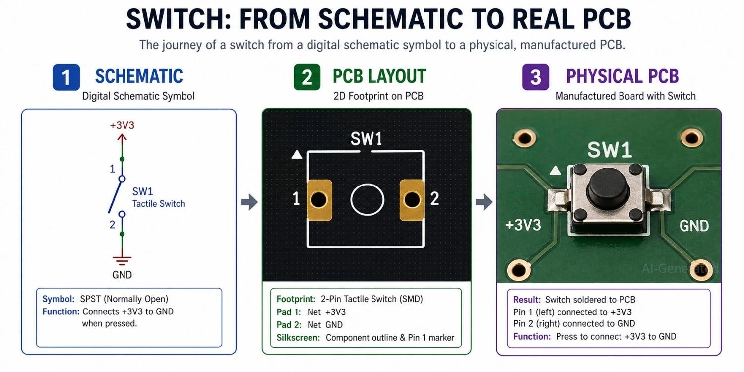
Figure: Showing a switch transitioning from a digital schematic symbol, to a PCB footprint layout, and finally to a physical SMD switch soldered on a manufactured board.
Map Schematic Symbol to PCB Footprint
The first and most critical step is linking the logical switch symbol to the correct physical footprint.
- Pin mapping: Ensure each schematic pin correctly corresponds to the physical pads on the PCB
- Orientation: Verify footprint rotation and alignment to avoid mirrored or reversed connections
- Pad geometry: Check pad size and shape for reliable soldering
- Datasheet validation: Always cross-check footprint dimensions and pin definitions with the manufacturer’s datasheet
Even a small mismatch here can lead to non-functional or difficult-to-debug boards.
Choose the Right Switch Footprint
Switches come in many mechanical forms, and selecting the right footprint is essential for both functionality and manufacturability.
- Through-hole vs SMD: Through-hole offers stronger mechanical stability, while SMD is better for compact designs
- Switch types: Tactile push buttons, toggle switches, and slide switches all require different layouts
- Mechanical clearance: Ensure enough space for actuation and enclosure integration
Incorrect footprint selection can result in assembly issues or poor user experience.
Route Signals and Power Correctly
Once the footprint is defined, routing determines how reliably the switch performs in the circuit.
- Trace width: Size traces based on expected current to prevent overheating or voltage drop
- Signal vs power paths: Distinguish between low-current signal switching and high-current power switching
- Noise considerations: Avoid routing sensitive signals near high-current paths to reduce interference
Proper routing ensures stable operation, especially in mixed-signal or high-speed designs.
Validate the Design Before Production
Before sending your PCB for fabrication, thorough validation is essential.
- ERC/DRC checks: Detect electrical and layout rule violations
- Netlist verification: Confirm that schematic and PCB connections are consistent
- Common mistakes:
- NO/NC misinterpretation
- Floating nodes
- Incorrect default switch state
Catching these issues early can save significant time and cost.
PCB Fabrication and Assembly
After validation, prepare your design for manufacturing.
- Generate and review Gerber files
- Provide a complete BOM (Bill of Materials) and CPL (Component Placement List)
- Confirm component availability and footprint compatibility
Ensuring Reliable Assembly with JLCPCB
To further improve build consistency, professional PCB assembly services can help reduce variability during production.
- Consistent solder quality: Automated SMT assembly ensures stable electrical connections
- Accurate component placement: Minimizes alignment and polarity errors
- Efficient prototyping to mass production: Streamlines the transition from design to finished product
This is especially valuable for switch-based designs that require repeated mechanical actuation and long-term reliability.

- Ready to turn your control circuits into physical reality?
- Ensure your physical components are routed and placed perfectly by relying on JLCPCB
FAQs About Switch Symbol
Q: What does a switch symbol represent?
It represents a component used to control circuit connections.
Q: What is normally open vs normally closed switch?
Normally Open (NO) means the circuit is broken by default. Normally Closed (NC) means the circuit is connected and flowing by default.
Q: What is SPST vs SPDT switch symbol?
SPST controls a single ON/OFF path. SPDT takes one input and lets you choose between two different output paths.
Q: How to identify switch position in a schematic?
Look at the angled line (the lever). If it touches both terminal circles, the switch is currently closed. If there is a gap, it is open.
Q: Are switch symbols standardized?
Yes, though you will see slight visual variations depending on whether the schematic follows US (ANSI) or international (IEC) design standards.
Conclusion
Understanding the switch symbol is a foundational skill in electronics. Because these symbols visually indicate how current flow is controlled, they are essential for deciphering user inputs, logic routing, and power management. By recognizing the difference between NO, NC, SPST, and SPDT switches, you can easily trace the operational states of any schematic diagram.
Popular Articles
• How to Identify SMD LED Polarity: Markings, Testing, and PCB Tips
• How to Create a Bluetooth-Controlled Car With Arduino: A Step-by-Step Guide
• How to Design and Assemble a Reliable ESP32 Module PCB on a 2-Layer Board
• The Ultimate Guide to Relay Symbol: Coil, Contacts, Diagrams, and Circuit Applications
• The Ultimate Guide to PCBA: Process,Types and Techniques for the Electronics Enthusiast
Keep Learning
How to Design an ESP32-S3 Development Board from Scratch: A 4-Layer PCB Design Tutorial
Designing your own ESP32-S3 development board gives you complete control over your hardware architecture while preparing your IoT projects for commercial production. Instead of relying on bulkier, off-the-shelf boards, building a custom design allows you to optimize the board space, expose only the required GPIO pins, and integrate peripherals directly onto a single substrate. In this tutorial, we will design a 4-layer ESP32-S3 development board from scratch. We will walk through the entire hardware d......
Circuit Breaker Symbols Explained: IEC, ANSI, MCB, and Pole Configuration Symbols
Electrical schematics are the universal language of power systems, control circuits, and printed circuit boards. Within these diagrams, the circuit breaker symbol is one of the most critical elements. Getting it right is essential for safety, troubleshooting, and manufacturing. An error as simple as mixing up a circuit breaker with a manual switch or an isolator can lead to catastrophic misinterpretations on the factory floor or during field maintenance. This guide provides a complete, technically acc......
How to Identify SMD LED Polarity: Markings, Testing, and PCB Tips
Surface-mount LED components are ubiquitous in electronics design, serving as everything from simple power indicators to complex lighting arrays. Unlike standard resistors, LEDs are polarized diodes. Identifying SMD LED polarity correctly is critical for prototype troubleshooting and high-volume PCB assembly. A reversed LED results in no light output, broken circuit paths, and potential diode breakdown if the reverse voltage exceeds the component's maximum rating (typically 5V or less for most indicat......
Arduino LED Driver Tutorial: Control More LEDs with 74HC595 and MAX7219
Arduino GPIO pins run out quickly in larger LED projects. By utilizing dedicated LED drivers and expansion ICs, you can drastically reduce pin usage, eliminate processor-heavy multiplexing loops, and simplify display wiring. In this guide, you will learn the operational architecture, wiring configurations, cascading techniques, and optimization strategies for the 74HC595 shift register and the MAX7219 LED driver. Why Arduino Projects Need LED Driver ICs Arduino GPIO and Current Limitations An ATmega32......
How to Create a Bluetooth-Controlled Car With Arduino: A Step-by-Step Guide
This tutorial walks through the complete engineering and implementation of a two-wheel Bluetooth RC car with an Arduino Nano module on a specially designed PCBA (Printed Circuit Board Assembly). While many hobbyists start by wiring motors and Bluetooth modules with jumper cables on a breadboard, this approach is prone to disconnection and signal noise. This guide upgrades that process by teaching you how to design a professional mainboard. Key Design Features Controller: Arduino Nano used as a plug-in......
Fiducial Marks in PCB and SMT Assembly: A Complete Guide to Accuracy and Design Rules
Modern Printed Circuit Boards (PCBs) are complex, integrating high-density components like 0.4mm pitch Ball Grid Arrays (BGAs), 0201 passives, and fine-pitch Quad Flat No-Lead (QFN) packages. In this advanced manufacturing environment, achieving placement accuracy measured in micrometers is crucial. A significant challenge in automated manufacturing is how pick-and-place machines, which handle thousands of components per hour, precisely locate the PCB. A board on a conveyor system is never in the perf......