How to Solder Pin Headers: A Step-by-Step Guide
12 min
- Introduction
- Quick Answer: How to Solder Pin Headers
- Types of Pin Headers
- What You Need to Solder Pin Headers
- How to Solder Through-Hole Pin Headers Straight, Step by Step
- How to Solder Right-Angle Pin Headers
- How to Solder SMD Pin Headers
- How to Desolder Pin Headers
- Common Pin Header Soldering Problems (and Fixes)
- FAQ about How to Solder Pin Headers
Key Takeaways
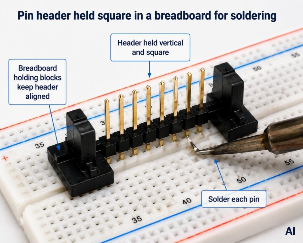
Breadboard or jig: Use a breadboard or jig to hold the header pin square while you work.
Tack one pin first: Check alignment before soldering the rest.
Keep heat brief: So the plastic housing doesn't melt.
Cut breakaway strips: Score the plastic between pins, not by forcing a cut mid-pin.
SMD headers: Soldered with paste and reflow rather than through-hole technique.
Desolder a pin: Add fresh solder plus wick or a pump, or use hot air.
Introduction
You solder a header pin, look at it, and it's leaning — so it won't seat cleanly into a breadboard or mating socket. Getting the header pins straight and clean is really a particular ability, apart from general soldering pin headers skills, and the crooked-header moment is a familiar irritation for anyone new to hand assembly. This guide covers how to solder pin headers — through-hole and SMD — so they come out straight every time, along with how to cut breakaway strips to length and how to desolder a header pin when one needs to come off.
For general iron, flux, and tinning fundamentals, see the PCB soldering basics guide; this article focuses specifically on header technique.
Quick Answer: How to Solder Pin Headers
To solder pin headers straight, seat the header in the board and hold it square using a breadboard or jig. Solder just one end pin first, check the alignment, and re-heat that pin to correct any lean. Once straight, solder the remaining pins and re-flow the first.
Types of Pin Headers
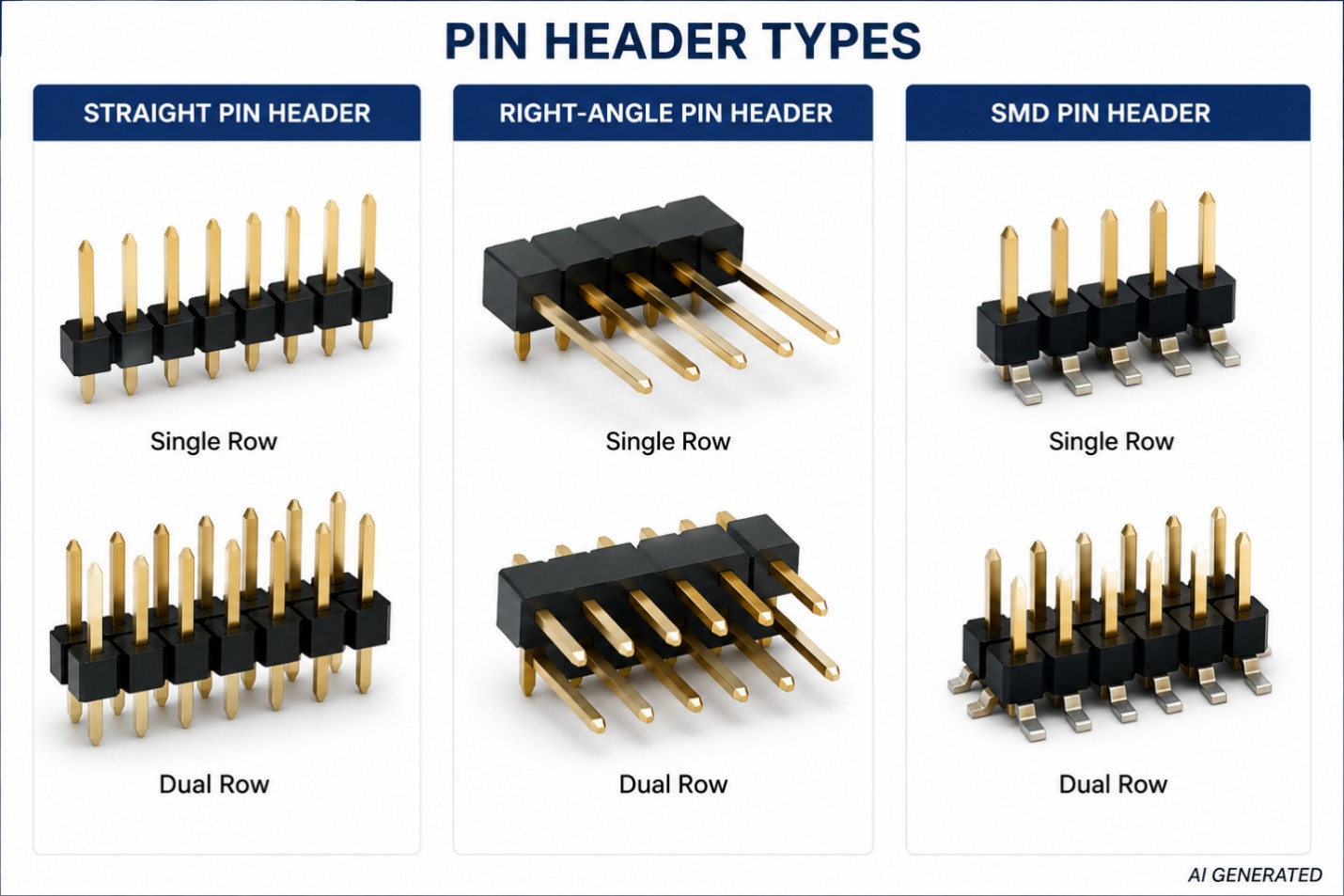
Pin headers come in a few variations, and each one changes how you should approach soldering pin headers. Male headers have exposed pins; female headers (sockets) accept a mating pin. Common pitches are 2.54 mm (0.1″), 2.0 mm, and 1.27 mm, with the pitch shrinking as boards get denser. In addition to straight and right-angle varieties, headers are available in single-row and multi-row configurations, as well as length-adjustable breakaway strips. In addition to the mounting manner, there are two types of headers: through-hole, which put the pins into plated holes, and SMD, which sits directly on top of the board.
All of these variations can be traced back to method. A smaller iron point and an increased likelihood of bridging adjacent pins are the results of a finer pitch. Because the body is flat on the board rather than standing on it, a right-angle header pin requires a different grip than a straight one. Also, surface-mount headers are not just a variant of the through-hole technique; they are their own distinct procedure that will be discussed further on in this manual.
What You Need to Solder Pin Headers
Aside from the standard soldering pin headers' kit, there are a handful of header-specific considerations:
- An iron that can be adjusted to the right temperature and has a chisel or bevel tip so it can make good contact with the pin and the pad.
- Solder with a rosin core, together with an additional small amount of flux for use with SMD headers and recalcitrant or oxidized pads.
- Flush cutters, for sizing breakaway strips cleanly.
- A breadboard or a 3D-printed jig, to hold the header square while it's soldered.
- Tweezers or helping hands, especially useful for SMD headers.
- Isopropyl alcohol (IPA), for cleaning flux residue once you're done.
How to Solder Through-Hole Pin Headers Straight, Step by Step
- To make the header pin the right size, use flush cutters to score the plastic in between the pins, and then either snap or neatly cut it. Protect your eyes from flying pins by wearing goggles.
- With the header's pins facing the side you will be soldering from, seat it in the board from the component side.
- To keep it level during soldering, wedge the pins into a breadboard or use a jig to position the strip at a right angle to the board.
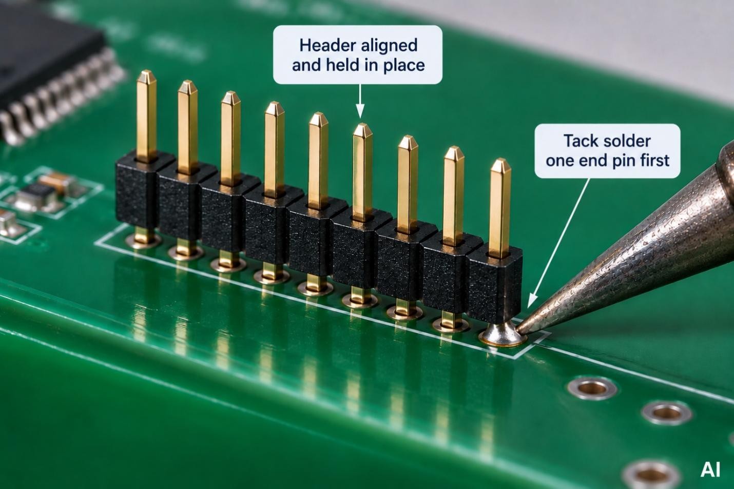
- Apply a small amount of solder to one end of the pin at a time while heating the pad and pin together; then, remove from heat.
- Reheat the one pin that is sagging and push it square before letting it cool; this will fix the header if it is leaning.
- After checking the alignment again, solder the pin at the other end. Then, using clean, cone-shaped fillets, solder all of the other pins.
- Because it was inserted prior to final alignment, the initial tack pin should be re-flowed since it might not be a fully formed joint at this point.
- Examine the end product; the fillets ought to be glossy and cone-shaped devoid of bridges, and the header ought to rest flat and parallel.
The One-Pin Trick: Getting Headers Perfectly Straight
The reason to tack a single pin — not two — is that one soldered joint can still be re-melted and nudged freely in any direction. As soon as a second pin is soldered, the header is locked into whatever angle it happened to be at, and correcting a lean means desoldering a joint instead of simply re-heating and adjusting it. Tacking one pin first, checking it, and only then committing to the rest is what separates a straight header from a crooked one.
Cutting Breakaway Headers to the Right Length
Count out the number of pins you need, then score the plastic body between that pin and the next one using flush cutters. Small strips can usually be snapped by hand once scored; for a cleaner edge, or on longer strips, cut through fully instead. On some header types, cutting mid-strip consumes the pin at the cut point, so it's worth counting on one extra pin.
How to Solder Right-Angle Pin Headers
Right-angle header soldering is trickier as to align as their body sits flat against the board instead of standing upright. Rest the board on its edge, or use a jig, so the pins are accessible and the header stays supported. Tack one pin first, verify that the horizontal row is parallel to the board's edge, then solder the rest. The same one-pin trick used for straight headers applies here — a single tacked joint can still be re-heated and adjusted before you commit to the whole row.
How to Solder SMD Pin Headers
SMD headers are a genuinely different process, since there are no through-holes involved — the header sits directly on surface pads. By hand, the approach is to add flux, tin one pad, place and tack the header on that pad, verify alignment, then solder the remaining pads. Fine-pitch SMD headers are often drag-soldered, dragging a small bead of solder along the row rather than working pad by pad.
The cleaner route for SMD headers — and for the rest of the SMT side of the board — is paste and reflow: a solder paste stencil deposits the right amount of paste on every pad in one pass, and the board is then reflowed as a batch rather than hand-soldered pad by pad. Through-hole headers on an otherwise SMT board can also be handled this way, using pin-in-paste: paste is deposited in the plated barrels and the header is reflowed along with the SMDs. For more on the reflow side of this, see the solder SMD components like a pro and reflow soldering guides. Ordering details for stencils are in the card below.
How to Desolder Pin Headers
Removing a whole multi-pin header is harder than removing a single component, because every pin needs to be molten at roughly the same time for the header to lift cleanly. There are three common approaches: adding fresh solder to bridge the row of pins and heating them together while gently pulling; working pin-by-pin with a solder sucker or wick; or, best of all, using hot-air rework to bring every pin up to temperature at once before lifting the header off.
If a header is damaged and being replaced anyway, it's often easier to cut the plastic body off with flush cutters first, then desolder each pin individually — without the plastic holding the pins together, there's less risk of tugging on the board. Clear each hole with wick or a solder pump before fitting the new header. See the solder bridging guide for more on clearing bridged or blocked pads.
Common Pin Header Soldering Problems (and Fixes)
| Problem | Cause | Fix |
|---|---|---|
| Crooked or tilted header | Too many pins were soldered before checking alignment. | Re-heat one end pin and nudge it square. |
| Solder bridges between pins | Too much solder, often on fine-pitch headers. | Add flux and wick away the excess, use a smaller tip, and feed less solder next time. |
| Melted or bulging plastic | The iron's temperature or the dwell time is too high. | Reduce the dwell time on each pin/pad and avoid keeping the soldering iron on one point; wait for each pin to cool before moving on to the next one. |
| Cold or dull joints | The joint did not receive enough heat, usually because a ground pin was drawing heat away from it. | Incorporate flux, heat the pad and pin for a longer period, and incorporate thermal-relief pads into the board's architecture. |
| Lifted pad | Excessive heat or force while desoldering. | Use hot air instead of prying and never yank a header free. |
For the acceptance criteria behind what counts as a good through-hole joint — fillet shape and hole fill — IPC-A-610 (Acceptability of Electronic Assemblies) is the standard reference, and IPC J-STD-001 covers the general soldering process requirements behind it.
FAQ about How to Solder Pin Headers
Q: What temperature should I use to solder pin headers?
Leaded solder works well with most pin headers between 315 and 370°C (600 and 700°F), while lead-free alloys require a little higher temperature. Since the plastic housing is melted by excess heat rather than a shortage of solder, it is best to start at the lower end and only increase if joints are not flowing quickly.
Q: Why does my header keep leaning even after I check it?
In most cases, this indicates that the lean was locked in by soldering a second or third pin before the first one was checked for straightness. Don't try to bend it straight while it's fully soldered. Instead, desolder back to a single tacked pin, re-align, and then re-solder the rest.
Q: Can I solder a header into a hole that's slightly too small?
While a snug fit may not always be an issue, it is possible to shatter the plated barrel or lift a pad by driving a pin into an inadequate hole. Make sure the hole is the same size as the header's pin diameter before applying further force if the pin still would not seat with gentle pressure.
Q: Do female headers solder any differently than male headers?
Although both use the one-pin approach, soldering female headers requires a shorter heat cycle to prevent melting the housing at the connection since their plastic bodies are closer to the pads.
Q: Is it safe to reuse a header after desoldering it?
You may usually reuse male headers with solid pins as long as they are in excellent shape. The plastic casing and internal connections of female headers make them more delicate and require careful examination. Make sure the housing is not melted or otherwise deformed, that the pins and contacts are straight, and that the plating is not broken from heat or mechanical stress before reusing. Instead of reusing a header that has sustained substantial damage during desoldering, it is recommended to get a new one.
Q: Why do my SMD header pads tombstone during reflow?
Tombstoning happens when one end of a pad heats and wets before the other, pulling the header up on one side. It's most common with uneven paste deposits or inconsistent pad heating, which is part of why a stencil-and-reflow approach tends to be more consistent than hand-tinning individual SMD pads.
Conclusion: Soldering Pin Headers Cleanly, Every Time
Two things are crucial while soldering pin headers: first, holding the strip square and tacking one pin before moving on to the rest; second, utilizing brief, controlled heat to ensure the plastic housing survives. That one-pin method is the foundation of through-hole headers, a manual skill. When it comes to surface-mount devices (SMD) and pin-in-paste through-hole headers, the use of paste and a stencil becomes necessary.
With the one-pin trick and the right heat, straight, reliable headers become routine. For related technique, see how to solder wires to a circuit board and 12 soldering tips for reliable joints.
Keep Learning
How to Solder SMD LEDs: A Step-by-Step Guide for Iron, Hot Air, and Reflow
Key Takeaways Confirm polarity and orientation first: Identify the anode and cathode before applying any heat, because a reversed SMD LED will not light and correcting it costs another thermal cycle. Match the method to the job: A fine-tip iron suits one or a few LEDs, hot air is best for rework and single-part replacement, and solder paste with reflow is fastest for complete boards. Keep solder and heat minimal: A small, fully wetted fillet and short dwell times protect the LED die, phosphor, and enc......
How to Solder a Potentiometer (PCB, Panel & Guitar Pots)
Key Takeaways Identify the wiper terminal: In most potentiometers, the middle pin is the wiper. Always verify with a multimeter before soldering. Pre-tin surfaces: Tin both the terminals and wires before joining to ensure strong, clean solder joints. Control heat carefully: Use a temperature-controlled iron and keep contact time short (below 260°C for a few seconds) to avoid damaging the internal resistive track. Test after soldering: Always check continuity and sweep the shaft while measuring output ......
How to Solder QFN Components: A Step-by-Step Guide
Key Takeaways A solder paste stencil is the most reliable way to achieve consistent QFN solder joints. Always use a window-pane paste pattern on the center thermal pad instead of one large paste deposit. Control solder paste volume to prevent floating, bridging, and excessive voiding. Reflow needs a proper soak-then-reflow-then-cool profile Hand soldering is practical only for certain QFN packages and usually cannot solder the center thermal pad effectively. Because QFN solder joints are hidden beneat......
How to Solder Pin Headers: A Step-by-Step Guide
Key Takeaways Breadboard or jig: Use a breadboard or jig to hold the header pin square while you work. Tack one pin first: Check alignment before soldering the rest. Keep heat brief: So the plastic housing doesn't melt. Cut breakaway strips: Score the plastic between pins, not by forcing a cut mid-pin. SMD headers: Soldered with paste and reflow rather than through-hole technique. Desolder a pin: Add fresh solder plus wick or a pump, or use hot air. Introduction You solder a header pin, look at it, an......
Hot Air Surface Mount Soldering: A Step-by-Step Guide
Key Takeaways Heat Control Is Everything: Hot air SMD soldering delivers uniform heat across all pads simultaneously, eliminating the lifted pads and cold joints common with iron-based soldering of fine-pitch components. Airflow Kills Small Parts: Set airflow to just 10–20% for 0402/0201 passives to avoid the Bernoulli Effect that turns tiny resistors into projectiles. Stencil Precision Prevents Tombstoning: A precision-cut SMT stencil deposits equal paste volume on both pads, balancing surface tensio......
Solder Bridging: Preventing a Common PCB Soldering Defect
Modern electronics demand compact PCB layouts with dense pad spacing and miniature components. Engineers deploy 0201 packages, fine pitch QFN devices, and large BGA arrays across SMT assembly lines. These layout conditions increase complexity during reflow soldering and raise the probability of PCB soldering defects. Solder bridging appears frequently within high-density boards that contain narrow pad spacing and large solder paste deposits. A solder bridge forms an unintended conductive path between ......