Capacitor Types Explained: Applications, Differences, and Selection Guide
17 min
- Capacitor Types Chart at a Glance
- Capacitor Type Comparison Table
- The Main Capacitor Types Explained
- Which Types of Capacitors Should You Use?
- How to Choose the Right Capacitor Type (5 Key Selection Criteria)
- Common Capacitor Selection Mistakes
- Capacitor Types and Their Applications
- Polarized vs Non-Polarized Capacitors
- From Capacitor Selection to PCB Assembly
- Conclusion
- FAQs about Capacitor Types
Capacitors are the most widely used parts in electronics design, from input/output coupling to bypassing and decoupling networks; they find applications everywhere. And if you get the wrong part/value placed, the consequences may be you get an audible whine from a supply rail, a bootloader that won't start, or a capacitor that lights up like a match.
The question that never comes up is "which brand?" It's always “which type and what value.” This tutorial does not waste time on a textbook explanation of the dielectrics, and only a few types are really relevant to the question you have on the bench: What type of capacitor should you put in this job?
Capacitor Types Chart at a Glance
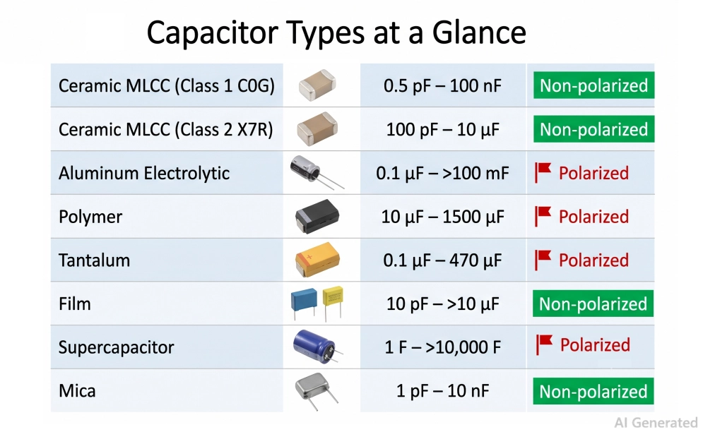
Figure: Capacitor types chart comparing ceramic, electrolytic, tantalum, film, polymer, supercapacitor, and mica capacitors with typical value ranges
The capacitor types are the families of capacitors that are formed based on the type of dielectric material and the type of insulator between the plates, which determines most of the important features, such as capacitor range, voltage rating, ESR, stability, size, etc., and also whether the capacitor is polarized or not.
They are mainly of the ceramic (MLCC), aluminum electrolytic, polymer, tantalum, film, supercapacitor, mica, and trimmer/variable types.
With that one sentence in mind, 90% of the selection is clear: select the dielectric which is appropriate to the job, then size the value and voltage. The quick reference chart is below. Scan it, and then go to the decision table for your particular application.
Capacitor Type Comparison Table
| Capacitor Type | Dielectric | Value Range | Voltage Range | ESR | Temp Stability | Polarized | Best For | Quick Take |
|---|---|---|---|---|---|---|---|---|
| MLCC Class 1 | C0G/NP0 ceramic | 0.5 pF – 100 nF | 4 V – 3 kV | Very low | Excellent (±30 ppm/°C) | No | RF, timing, precision filters | Ultra-stable, low-loss, small values |
| MLCC Class 2 | X7R/X5R/Y5V ceramic | 1 nF – 100 µF | 4 V – 100 V | Very low | Poor–fair (drifts, DC bias) | No | Decoupling, general bypass | High density, cheap, but drifts with voltage/temp |
| Aluminum electrolytic | Aluminum oxide | 1 µF – 100,000 µF | 6.3 V – 550 V | High | Fair | Yes | Bulk smoothing, mains filtering | Cheap bulk capacitance, higher ESR |
| Polymer | Al/Ta polymer | 1 µF – 2,200 µF | 2 V – 100 V | Very low | Good | Yes | SMPS output, CPU power | Low ESR bulk, long life, higher cost |
| Tantalum | Tantalum pentoxide | 0.1 µF – 1,000 µF | 2 V – 63 V | Low–medium | Good | Yes | Compact stable bulk | Stable, compact bulk, but hard to derate |
| Film | PP / PET | 1 nF – 100 µF | 50 V – 2 kV | Very low | Very good | No | Audio, snubbers, AC line | Precise, low-loss, AC-friendly, bulky |
| Supercapacitor | EDLC / activated carbon | 0.1 F – 3,000 F | 2.5 V – 5.5 V/cell | High | Fair | Yes | Backup power, energy storage | Energy storage/backup, very low voltage |
| Mica | Silver mica | 1 pF – 10 nF | 100 V – 10 kV | Very low | Excellent | No | RF resonant, precision | Extreme stability/precision for RF |
| Trimmer/variable | Air/ceramic/PTFE | 1 pF – 100 pF | 100 V – 250 V | Low | Good | No | Tuning, calibration | Tunable, for calibration/tuning |
- Get a PCBA quote and go from schematic to assembled boards fast.
The JLCPCB Parts Library stocks a huge range of ceramic, tantalum, polymer, aluminum, and film capacitors. All traceable and ready for automated placement. Pick your capacitor types in the BOM, upload your Gerbers, and JLCPCB fabricates the PCB and populates the caps in one order, so what you selected here is exactly what ships on your assembled board.
The Main Capacitor Types Explained
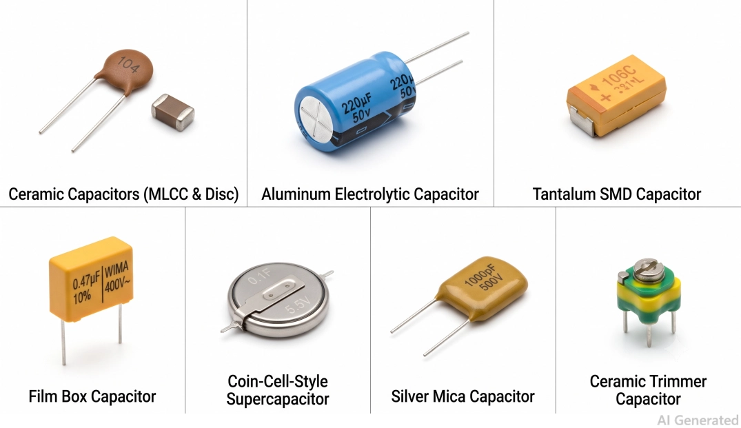
Figure: Different types of capacitors showing MLCC ceramic, aluminum electrolytic, tantalum, film, supercapacitor, mica, and trimmer capacitors
Ceramic Capacitors (MLCC) - Class 1 vs Class 2
Multilayer ceramic capacitors are non-polarized, inexpensive, and small, and serve as the backbone of today's boards.
Class 1 (C0G/NP0) is ultra-stable and low-loss, but is only applicable to a maximum of approximately 100 nF.
Class 2 (X7R, X5R, Y5V): Compromises for stability for density, excellent for decoupling, not for fixed value. For the full breakdown of dielectric codes and sizes, see the ceramic capacitor types guide.
Aluminum Electrolytic Capacitors
The lowest-priced microfarad available. Polarized, higher ESR, moderate lifetime (electrolyte dries with heat), but unbeatable for energy storage in large quantities and for smoothing out mains frequencies. Be aware of the temperature rating and ripple current since they determine its life.
Polymer Capacitors
Aluminum- or tantalum-polymer caps replace the liquid/oxide with a conductive polymer, providing very low ESR, long life, and no dry-out. They are the first choice for SMPS outputs and CPU/GPU power when transient response is a concern. This increase in cost and in voltage ratings is the trade-off.
Tantalum Capacitors
More compact, more polarization, more stable, bulk capacitance than aluminum. The downside: tantalums go short, and burn under reverse voltage, over-voltage, or high inrush, derate to <50% of the rated voltage, and use series resistance if inrush is high.
Film Capacitors (PP / PET)
Non-polarized, precise, low-loss, and happy with AC and high dV/dt. Polypropylene (PP) is the premium choice for audio, snubbers, and mains; polyester/PET is cheaper for general coupling. The downside is the size of the bulk film for a given capacitance.
Supercapacitors
Farads in a coin or can. Extremely high capacitance at low voltage for backup power, energy harvesting, and hold-up.
Silver Mica Capacitors
Silver mica offers exceptional stability, precision, and Q at high frequency, which is why it survives in RF-tuned circuits and precision timing despite the cost and limited value range.
Variable (Trimmer) Capacitors
Small adjustable capacitors (typically 1–100 pF) are used to tune oscillators, filters, and antenna matching by hand during calibration.
| Capacitor Type | Best For | Advantages | Limitations |
|---|---|---|---|
| Ceramic | Decoupling | Low ESR | DC Bias |
| Electrolytic | Bulk Filtering | High Capacitance | Shorter Lifetime |
| Polymer | SMPS | Very Low ESR | Lower Voltage Ratings |
| Tantalum | Compact Designs | High Capacitance Density | Sensitive to Surge |
| Film | Audio | Low Distortion | Large Size |
| Supercapacitor | Backup | Huge Capacitance | Low Voltage |
| Silver Mica | RF | High Q | Expensive |
| Variable | RF Tuning | Adjustable | Small Capacitance |
Which Types of Capacitors Should You Use?
| Application | Recommended Type | Why + Typical Value |
|---|---|---|
| Decouple /bypass an IC | Class 2 MLCC (X7R/X5R) | Low impedance at HF, 100 nF per power pin, plus 1–10 µF nearby |
| Bulk power-supply smoothing | Aluminum electrolytic or polymer | High capacitance for ripple hold-up; 100–1000 µF at a buck output |
| Low-ESR output filter (SMPS) | Polymer or ceramic bank | Low ESR kills ripple and improves transient response; 22–220 µF |
| Timing/oscillator/filter | C0G/NP0 MLCC or film | Value must not drift; 10 pF – 10 nF with very tight tolerance |
| Audio signal coupling | Film (PP/PET) or bipolar electrolytic | No DC-bias distortion, stable value; 0.1–10 µF |
| RF/matching /resonant | Class 1 MLCC or mica | Ultra-low loss, stable with frequency; 0.5 pF – 1 nF |
| Motor-run /start | Film (run), non-polar electrolytic (start) | Rated for continuous AC current; µF-class |
| AC line filtering (mains) | X and Y safety film | Fail-safe, agency-rated for mains; 10 nF – 1 µF X2 |
| Snubber across a switch | Film (PP) | Handles fast dV/dt and pulse current; 1–100 nF |
| Energy storage/backup | Supercapacitor | Rides through power loss, holds RTC/RAM; 0.1–10 F |
| High-temp / automotive | C0G, film, or AEC-Q200 MLCC | Survives 125–150 °C and vibration |
Note
Remember one thing: Choose ceramic for high frequency and decoupling, electrolytic/polymer for bulk energy storage, film for AC and precision, tantalum/polymer for compact, stable bulk, and supercap for backup.
How to Choose the Right Capacitor Type (5 Key Selection Criteria)
Once you know the application, five properties decide the exact part. Run through them in order, and the choice narrows to one or two types every time.
1. Capacitance and Voltage Rating
Start with the circuit's required value, then the working voltage. The rule of thumb is to derate the voltage to the maximum value, as they fail short and can ignite when overstressed.
Run ceramics at <50% of rated voltage where stability matters, aluminum electrolytics at 80%, and tantalums at 50% or less.
Example: A 16 V rail requires a 25 V (or higher) part, not a 16 V part. See our capacitor voltage rating guide for worked examples, and the capacitor value guide for reading values and codes.
2. ESR and Ripple Current
The series resistance found inside every capacitor is called the equivalent series resistance. Low ESR (Ceramic or Polymer) indicates low ripple voltage and cool operating under high ripple current.
For bulk hold-up, higher ESR (standard aluminum) is acceptable, but if the ripple is heavy, the device will self-heat, and its life will be shortened.
Always verify the ripple current rating, not only capacitance, of any bulk or output cap.
3. Frequency and Self-resonance
All capacitors are, in effect, LC circuits; they lose their ability to decouple above their self-resonant frequency (SRF). Low-value, small-package ceramics are superior in SRF, so 100 nF decoupling is preferable to a single 10 µF at high frequency.
Choose Class 1 ceramic or mica for RF and fast edge applications with low ESL and high SRF.
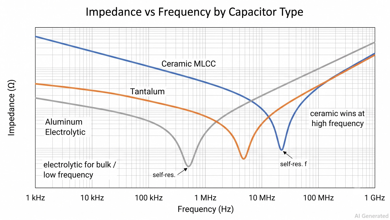
Figure: Capacitor impedance vs frequency curve comparing ceramic, tantalum, and electrolytic capacitor types across the frequency spectrum
4. Temperature Stability (Class 1 vs Class 2)
- Class 1 ceramics (C0G/NP0) are extremely stable (±30 ppm/°C), have no voltage dependence/aging, and are useful for small values.
- The capacitance loss of all Class 2 ceramics (X7R, X5R, Y5V) is significant and is lost over temperature (X7R ±15%, Y5V ±22%/-82%) and by DC-bias (all have a heavy loss).
Example: An X7R 10 µF can measure 3–4 µF at its rated voltage. Use Class 1 wherever the value must stay put.
5. Size, Cost, and Polarization
Last but not least, consider package size, cost, and if the part is polarized. If reversed, they are polarized and broken down to become electrolytes, tantalums, polymers, and supercapacitors. Non-polarized – goes either way – Ceramics, film, and mica.
In terms of size per microfarad, MLCC is the smallest, film is the largest, and tantalum is the cheapest.
Common Capacitor Selection Mistakes
Most capacitor failures trace back to a handful of avoidable errors. Check your design against these.
- Using X7R where C0G is needed: In a timing, filter, or precision circuit, a Class 2 ceramic drifts with temperature and loses capacitance to DC bias, so your frequency or cutoff moves. Use C0G/NP0 (or film) whenever the value must hold.
- Ignoring ripple and ESR on bulk caps: Specifying only microfarads on a supply cap gets it running hot. Check the ripple-current and ESR ratings; undersized electrolytics fail early, and high ESR means poor filtering and a warm part.
- Reversed or under-derated tantalum polarity; Tantalums fail short and can ignite under reverse voltage, over-voltage, or inrush. Confirm the + bar's orientation and derate to ≤50% of rated voltage.
- Non-safety-rated capacitor on the AC line: An ordinary ceramic or film cap across the mains can fail short and start a fire. Only agency-rated X (line-to-line) and Y (line-to-ground) safety capacitors belong there.
- Forgetting DC-bias loss in Class 2 MLCCs: That "10 µF" X7R can measure 3–4 µF at its rated voltage. Oversize the value or use a bigger case size so the effective capacitance is what you need.
Capacitor Types and Their Applications
Here's the core of the guide for the real-world jobs and the type that wins each one.
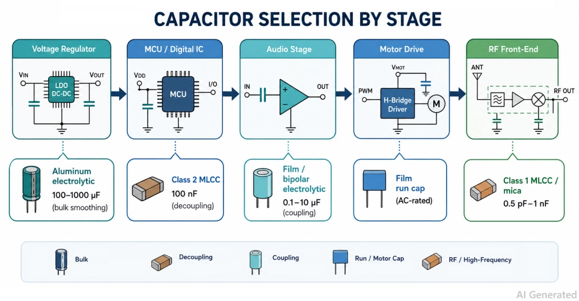
Figure: Mapping capacitor types to circuit applications, including decoupling, power supply smoothing, audio coupling, motor drive, and RF
Decoupling and Bypass
Each digital IC requires a local charge reservoir to provide the high currents that it demands during switching and prevent a sag in the power rail. It's a Class 2 MLCC (X7R/X5R) of 100 nF, right next to each power pin, with a 1-10µF bulk ceramic adjacent to it.
- The loop should be as small as possible, as the absolute value is not as important as the ESL. So, put the cap on the same side of the IC, via straight down to the plane.
- If a single value is insufficient, then a second, smaller ceramic can be added (e.g., 1nF), which will keep each part decoupled at its own self-resonant frequency. To read the difference between the two jobs, refer to the decoupling vs bypass capacitors.
Bulk Power-supply Smoothing
You must store energy and absorb ripple at a rectifier output/input or at any regulator. Use aluminum electrolytic for low cost, bulk (100 to 1000 µF and beyond), or polymer/tantalum when the same capacitance is needed in a smaller package with lower ESR.
The standard winning combination is a hybrid bank, a large electrolytic in parallel with an ESR-low ceramic or polymer that is fast enough to absorb high-frequency ripple that the electrolytic is too slow to capture.
Be mindful of the ripple-current rating and ESR; each 10 °C of SHT will approximately cut its rated life in half, providing some margin.
Audio Coupling
A coupling cap is used at each stage to pass the AC signal and to block the DC component(s); the value and linearity of the coupling cap should also be very steady.
- The superior sound and stability are obtained with the film (PP or PET), while for the large value, it is cheaper in the low-frequency path, using a bipolar (non-polar) electrolytic.
- If the value is related to load impedance, make the high-pass corner frequency around a factor of 10 lower than your lowest audio frequency, for "thinning out" the bass.
- Don't use Class 2 ceramics in the signal path: They change capacity as voltage changes, and this non-linearity becomes measurable harmonic distortion right at the point where the ear is sensitive to it.
Timing and Precision
RC timing, oscillators, filters, and integrators all fail if the capacitor drifts. Use C0G/NP0 Class 1 ceramic for small values or film for larger ones, both with tight tolerance. This is the classic mistake to avoid: an X7R in a timing network shifts your frequency with temperature and applied voltage.
RF and High-Frequency Circuits
At RF, you want minimal loss and stable capacitance versus frequency. Class 1 MLCC (C0G/NP0) handles most decoupling and matching; silver mica is the gold standard for high-Q resonant and tuned circuits. Both offer low ESL and a high self-resonant frequency, which cheap Class 2 parts can't match.
Motor, AC-line, and safety
Anything connected to AC mains or a motor winding must be rated for continuous AC and be fail-safe.
Motor run capacitors are film (µF-class, AC-rated) because they carry current continuously; motor start caps are non-polar electrolytic, sized larger but only in-circuit for a moment.
Across the mains, you must use safety-rated X and Y film capacitors, X2 across line-to-line, Y across line-to-ground. because they are designed to fail open, not short, and Y-class parts also meet the insulation requirement between mains and anything a person can touch.
Energy Storage and Backup Power
To ride through a power dropout or hold up an RTC/SRAM, you need farads, not microfarads. A supercapacitor stores enormous energy at low voltage and recharges for years, filling the gap between a big capacitor and a battery.
Mind the low working voltage (often 2.5–5.5 V per cell, so cells are stacked with balancing for higher rails), the leakage current that slowly drains it, and the inrush at power-up. A supercap looks like a near-short when empty, so add a charge-limiting resistor or current-limited path.
Polarized vs Non-Polarized Capacitors
The single fastest way to destroy a capacitor is sometimes the board around it when a polarized part is installed backward.
Polarized types (aluminum electrolytic, tantalum, polymer, supercapacitor) have a defined + and − and must see DC of the correct polarity.
Non-polarized types (ceramic, film, mica) work in either direction and handle AC.
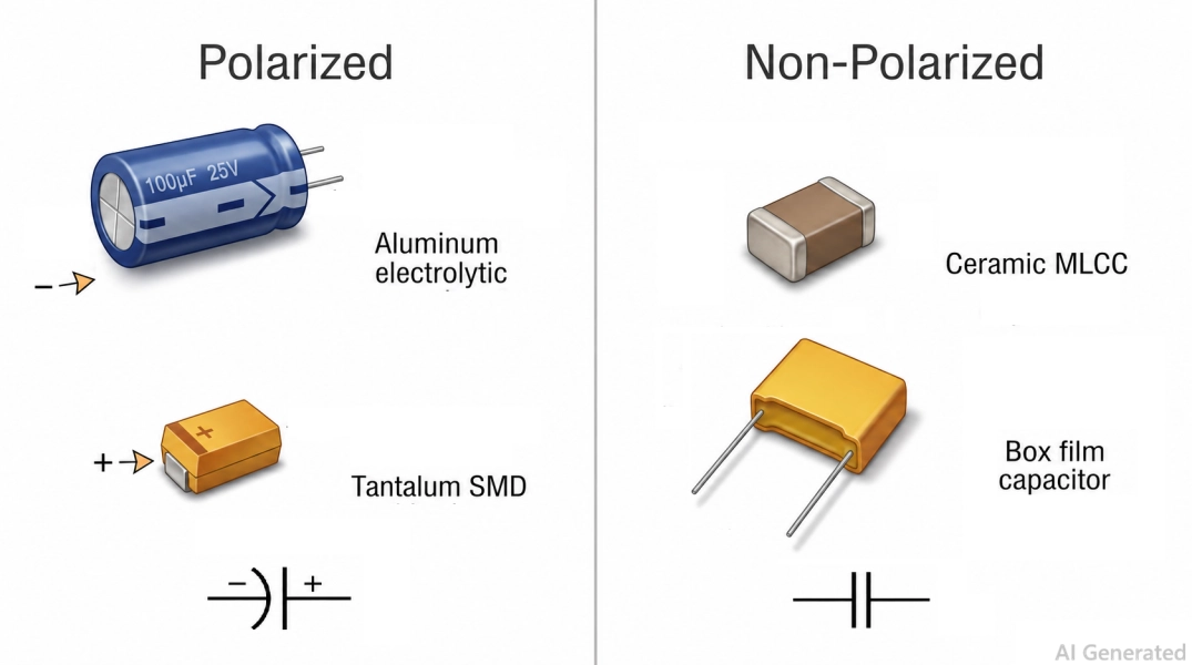
Figure: Polarized vs non-polarized capacitor types showing electrolytic and tantalum polarity marks versus ceramic and film capacitors
Identify polarity before you solder: aluminum cans mark the negative lead with a stripe; tantalums mark the positive end with a bar; through-hole electrolytics have a shorter negative leg.
On a schematic, the curved plate of the symbol is the negative side. If a node swings AC or you're unsure of polarity, use a non-polarized type.
From Capacitor Selection to PCB Assembly
Choosing the right capacitor type is only half the job; the part still has to land on a real board.
Once your BOM is set, you want genuine, in-stock components and clean SMT assembly, not counterfeits or hand-soldering hundreds of 0402s.
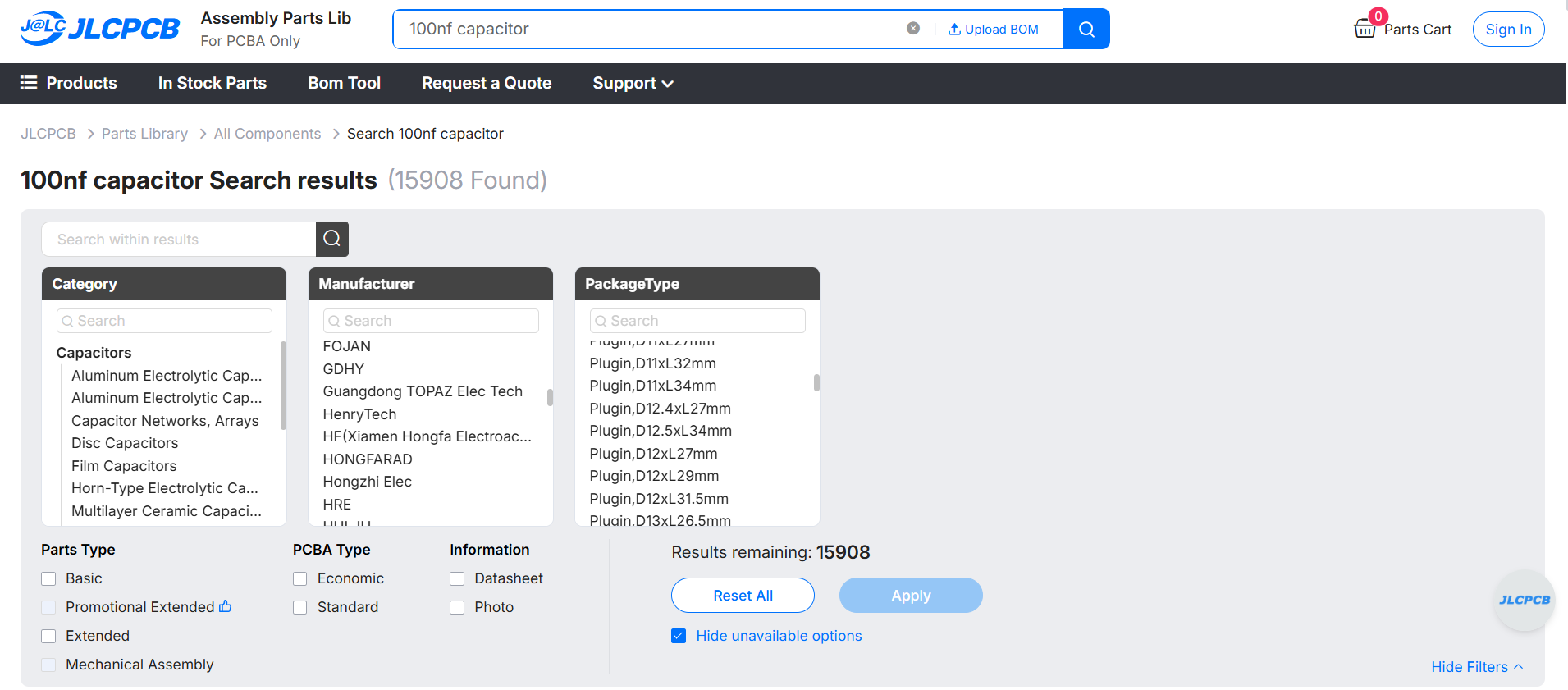
Figure: Search capacitor at JLCPCB Parts Library
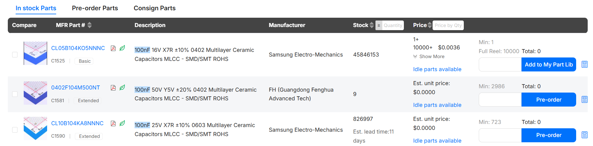
Figure: JLCPCB Parts Library showing capacitor types available for PCB assembly with stock and pricing
Conclusion
Choosing among capacitor types comes down to one habit: start from the application, not the parts bin.
Ceramic MLCCs handle decoupling and high frequency; aluminum, polymer, and tantalum store bulk energy; film owns AC, audio, and mains safety; supercapacitors cover backup.
Nail the five criteria: capacitance, voltage, ESR, frequency, and temperature stability. Remember to derate tantalums and account for Class 2 DC-bias loss, and you'll pick the right capacitor type every time.
When your BOM is ready, source verified capacitors and get them placed through the JLCPCB Parts Library.
FAQs about Capacitor Types
Q: How many types of capacitors are there?
There are around eight main capacitor types grouped by dielectric: ceramic (MLCC), aluminum electrolytic, polymer, tantalum, film, supercapacitor, mica, and trimmer/variable. Ceramic further splits into Class 1 (C0G/NP0) and Class 2 (X7R/X5R/Y5V). For most designs, you'll actually use ceramic, electrolytic, tantalum, and film.
Q: Which capacitor type should I use for decoupling?
Use a Class 2 MLCC (X7R or X5R). Place a 100 nF ceramic at each IC power pin with a 1–10 µF bulk ceramic nearby, keeping the loop short for low ESL. Their low high-frequency impedance and tiny footprint make them ideal for supplying the fast current spikes that digital ICs draw.
Q: What capacitor is best for power supply filtering?
For bulk smoothing, use aluminum electrolytic (cheap, high capacitance) or polymer/tantalum where you need low ESR in a smaller package. Combine a large electrolytic for energy storage with a small ceramic for high-frequency noise. Always check the ripple current and ESR ratings, not just the microfarad value.
Q: What's the difference between polarized and non-polarized capacitors?
Polarized capacitors (aluminum electrolytic, tantalum, polymer, supercapacitor) have a fixed + and − and must see DC of the correct polarity, or they fail. Non-polarized types (ceramic, film, mica) work in either direction and handle AC. Use non-polarized parts on any node that swings AC or coupling signals.
Q: Which capacitor type is best for audio coupling?
Film capacitors (polypropylene or polyester/PET) are best for audio coupling because their value is stable and linear with no DC-bias distortion. Bipolar (non-polar) electrolytes work when you need large values at low cost.
Popular Articles
• SMD Resistor Package Sizes: Complete Size Chart, Footprints & How to Choose
• How to Solder SMD Components Like a Pro [2026 Updated]
• SMD Resistor Codes: How to Read 3-Digit, 4-Digit, and EIA-96 Markings
• SMD Capacitor Codes: Identification, Markings, and Polarity
• SMD Capacitor Sizes: Complete Size Chart and Selection Tips for PCB Design and Assembly
Keep Learning
ESP8266 vs ESP32: Which One Should You Use?
Key Takeaways ESP32: Dual-core 240 MHz CPU, Bluetooth Classic and BLE, 520 KB SRAM, and up to 34 GPIOs. ESP8266: Single-core CPU, no Bluetooth, and around 50 KB of free RAM for applications. Lifecycle status: Espressif marks the ESP8266 Not Recommended for New Designs (NRND) and names the ESP32-C2 (ESP8684) as its upgrade, although the ESP8266 remains in production with a longevity commitment. Which ESP32 to use: Choose the ESP32-C2 for simple Wi-Fi or Bluetooth LE firmware, the ESP32-C3 for more memo......
What Is a Thermistor? A Practical Guide to NTC, PTC, Applications, and Circuit Design
Key Takeaways Definition: A thermistor is a thermally sensitive resistor whose resistance changes markedly and predictably with temperature, typically by about 4.4% per °C for a standard 10 kΩ NTC (B25/50 = 3950 K) near 25 °C. NTC vs. PTC: An NTC thermistor's resistance falls as temperature rises, which suits temperature sensing and inrush current limiting; a switching PTC's resistance rises steeply above its switch temperature, which suits circuit protection. Key Specifications: An NTC thermistor is ......
What Is the ESP32-CAM, and How to Wire, Power, and Program It?
Key Takeaways Board, not chip: The ESP32-CAM is an AI-Thinker development board, not an Espressif product. It carries AI-Thinker's ESP32-S module, an OV2640 camera, PSRAM, a microSD slot, and a flash LED. No USB port: The board has no USB connector or USB-to-UART bridge, so you program it via its serial pins using a 3.3 V USB-to-serial adapter, with GPIO0 held low at reset. Few free pins: The camera, PSRAM, and microSD card occupy most GPIOs. With the microSD card unused, GPIO2, GPIO4, GPIO12, GPIO13,......
ESP32 Versions: Which One Should You Use for Your Project?
Key Takeaways Radios decide first: ESP32 versions differ mainly in their radios, CPU cores, and peripherals. Common defaults: The ESP32-C3 suits low-cost Wi-Fi and Bluetooth LE, the ESP32-S3 suits camera, display, voice, and on-device AI. Original ESP32: The chip is still in production and remains the choice for Bluetooth Classic. Versions without Wi-Fi: The ESP32-H2 targets battery-powered Thread and Zigbee devices. Chip, module, or board: Prototype on a development board, then design a module onto y......
SOIC Package: A Complete Guide to Specifications, Types, Uses, and SMT Assembly
As designs transition from legacy through-hole components to high-density Surface Mount Technology (SMT), the Small Outline Integrated Circuit (SOIC) remains the industry standard for operational amplifiers, flash memory, sensors, and microcontrollers. It reflects a well-balanced engineering design, offering a practical compromise between the miniaturisation demanded by modern consumer electronics and the ruggedness required for industrial applications. In this guide, you will learn: SOIC package dime......
What Is a 100nF Capacitor and How Do You Choose the Right One
Key Takeaways Value: A 100nF capacitor has a nominal capacitance of 0.1 µF, or 100,000 pF, and all three names describe the same part value. Marking: Many through-hole ceramic and film capacitors use the three-digit code 104, while most SMD MLCCs are unmarked. Main use: Its most common function is local decoupling at an IC power pin, where it supplies fast transient current and shunts high-frequency noise to ground. Default choice: For general decoupling, an X7R or X5R MLCC is a common starting point;......