Ceramic Capacitor Code Guide: Values, Tolerance, and Voltage
14 min
- Ceramic Capacitor Code Chart: Values in pF, nF, and µF
- What Is a Ceramic Capacitor Code?
- How to Read a Ceramic Capacitor Code in 3 Steps
- Common Ceramic Capacitor Codes: 104, 103, and Other Frequent Values
- Other Ceramic Capacitor Marking Codes: R, p, n, and Decimal Notation
- Ceramic Capacitor Tolerance Codes: J, K, M, and More
- Ceramic Capacitor Voltage Codes and Ratings
- How to Read Full Ceramic Capacitor Marking: Dielectric, Safety, and Examples
- Ceramic Capacitor with No Code: How to Identify Unmarked SMD MLCCs
- Conclusion
- FAQs About Ceramic Capacitor Codes
Key Takeaways
- Three-Digit Rule: The first two digits represent the significant figures, while the third indicates the power-of-ten multiplier. The resulting capacitance is expressed in picofarads (pF).
- Common Values: Code 104 represents 100,000 pF (100 nF or 0.1 µF), while 103 represents 10,000 pF (10 nF or 0.01 µF).
- Tolerance Letters: Letters indicate capacitance tolerance. Common examples include J (±5%), K (±10%), and M (±20%). For small capacitance values, B, C, and D specify tolerances in pF.
- Voltage and Dielectric: The three-digit code does not specify voltage rating or dielectric type.
- Unmarked Capacitors: Most small SMD ceramic capacitors have no printed markings. Identify their values using the bill of materials (BOM), component reel label, or an LCR meter with the capacitor removed from the circuit.
A ceramic capacitor code helps you identify a capacitor’s capacitance value.
For example, the three-digit code 104 represents 100,000 pF, equal to 100 nF or 0.1 µF. A letter after the code, such as K in 104K, indicates the capacitance tolerance (±10%).
Voltage ratings and dielectric types must be identified through additional markings, the manufacturer's part number, or the datasheet.
In this guide, you will learn:
- How to read a three-digit ceramic capacitor code in three steps
- A code chart for common values in pF, nF, and µF
- What tolerance letters, voltage codes, and full markings mean
- How to identify ceramic capacitors that carry no printed code
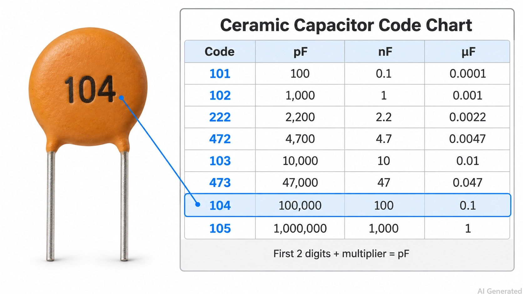
Figure: 100nF ceramic disc capacitor with a quick-reference chart of common ceramic capacitor codes in pF, nF, and µF.
Ceramic Capacitor Code Chart: Values in pF, nF, and µF
Common ceramic capacitor codes run from 100 (10 pF) to 226 (22 µF). To convert, divide the pF value by 1,000 to get nF, and divide the nF value by 1,000 to get µF.
| Code | Value in pF | Value in nF | Value in µF |
|---|---|---|---|
| 100 | 10 | 0.01 | 0.00001 |
| 101 | 100 | 0.1 | 0.0001 |
| 151 | 150 | 0.15 | 0.00015 |
| 221 | 220 | 0.22 | 0.00022 |
| 331 | 330 | 0.33 | 0.00033 |
| 471 | 470 | 0.47 | 0.00047 |
| 681 | 680 | 0.68 | 0.00068 |
| 102 | 1,000 | 1 | 0.001 |
| 152 | 1,500 | 1.5 | 0.0015 |
| 222 | 2,200 | 2.2 | 0.0022 |
| 332 | 3,300 | 3.3 | 0.0033 |
| 472 | 4,700 | 4.7 | 0.0047 |
| 682 | 6,800 | 6.8 | 0.0068 |
| 103 | 10,000 | 10 | 0.01 |
| 153 | 15,000 | 15 | 0.015 |
| 223 | 22,000 | 22 | 0.022 |
| 333 | 33,000 | 33 | 0.033 |
| 473 | 47,000 | 47 | 0.047 |
| 683 | 68,000 | 68 | 0.068 |
| 104 | 100,000 | 100 | 0.1 |
| 154 | 150,000 | 150 | 0.15 |
| 224 | 220,000 | 220 | 0.22 |
| 334 | 330,000 | 330 | 0.33 |
| 474 | 470,000 | 470 | 0.47 |
| 684 | 680,000 | 680 | 0.68 |
| 105 | 1,000,000 | 1,000 | 1 |
| 225 | 2,200,000 | 2,200 | 2.2 |
| 475 | 4,700,000 | 4,700 | 4.7 |
| 106 | 10,000,000 | 10,000 | 10 |
| 226 | 22,000,000 | 22,000 | 22 |
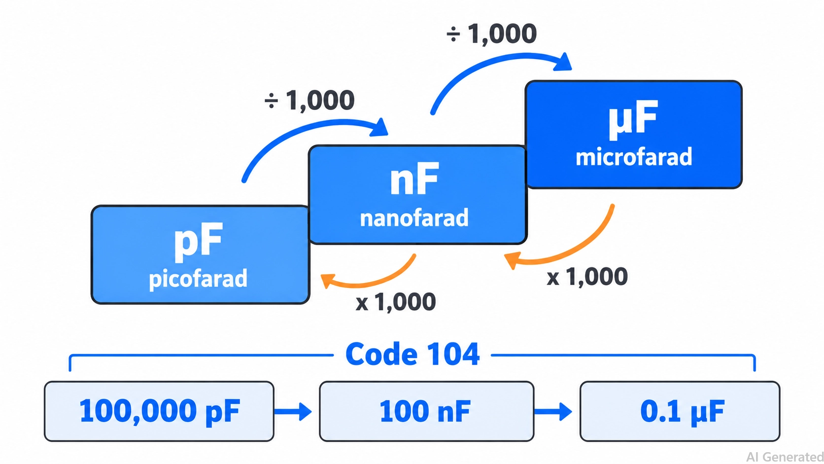
Figure: Unit ladder for ceramic capacitor values from pF to nF to µF, with each step dividing by 1,000.

Once you've verified the capacitance, tolerance, voltage rating, and dielectric type of each ceramic capacitor in your BOM, you're ready to proceed with PCB fabrication.
Upload your Gerber files to JLCPCB to check manufacturing options, pricing, and lead times for your board.
What Is a Ceramic Capacitor Code?
A ceramic capacitor code is a short marking, usually three digits, that gives the capacitance in picofarads (pF). The first two digits are the significant figures, and the third digit usually tells you how many zeros to add. For example, 104 is 10 followed by four zeros, or 100,000 pF (100 nF).
A complete marking can carry four kinds of information:
- Capacitance code: Three digits, such as 104, or a short value such as 22 or 4n7 on small parts.
- Tolerance letter: One letter after the digits, such as the K in 104K.
- Rated voltage: A value such as 50V or 1KV, printed when the body is large enough.
- Dielectric or safety class: A code such as X7R, or a safety class such as Y2 on mains-rated discs.
How to Read a Ceramic Capacitor Code in 3 Steps
To read a three-digit ceramic capacitor code, take the first two digits as a number, multiply it by ten raised to the power of the third digit, and read the result in pF. Then convert it to nF or µF.
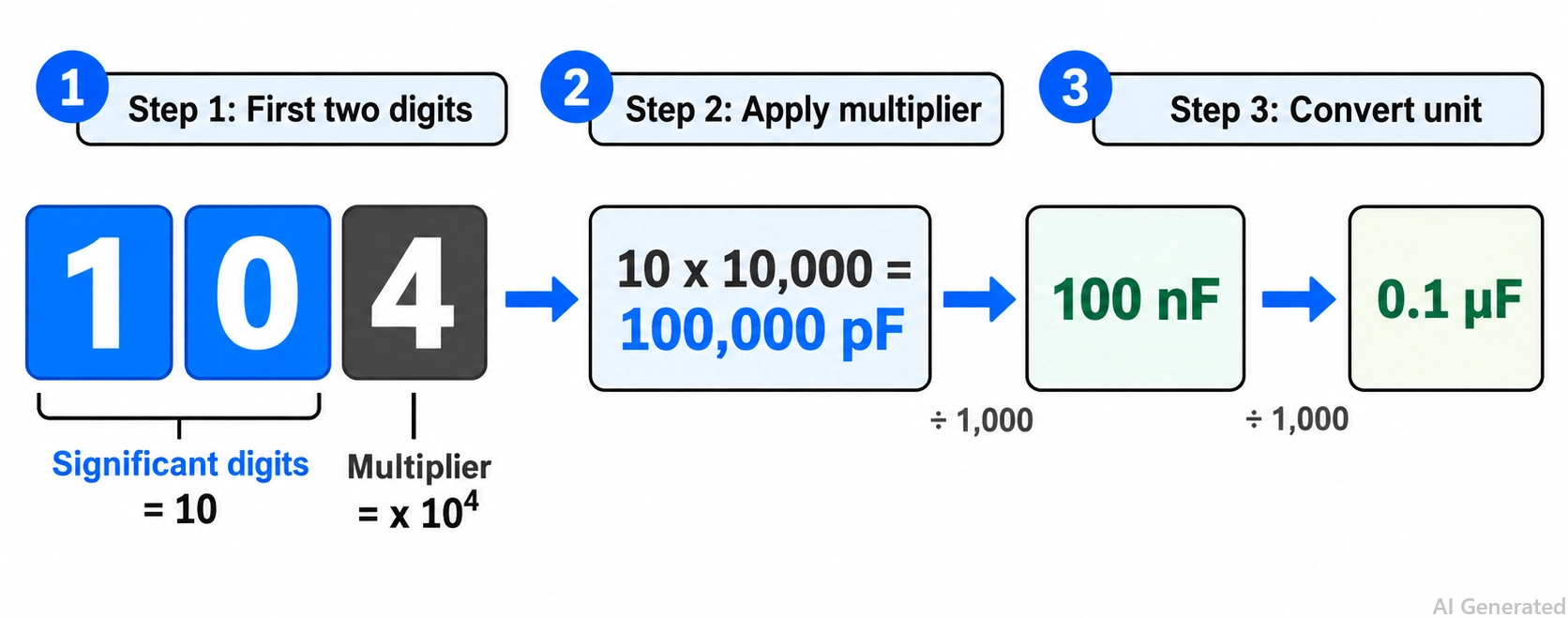
Figure: Ceramic capacitor code 104 decoded as 10 × 10⁴ pF, equal to 100 nF or 0.1 µF.
Step 1: Take the first two digits: For 104, the significant figures are 1 and 0, which gives 10.
Step 2: Apply the multiplier: The third digit, 4, means × 10⁴, so 10 × 10,000 = 100,000 pF.
Step 3: Convert the unit: Divide by 1,000 to get 100 nF, or by 1,000,000 to get 0.1 µF.
Common Ceramic Capacitor Codes: 104, 103, and Other Frequent Values
A 104 code is 100 nF (0.1 µF), and a 103 code is 10 nF (0.01 µF). They are among the most frequently used ceramic capacitor codes, because 100 nF and 10 nF are standard decoupling and filtering values.
104 Ceramic Capacitor Value
A 104 ceramic capacitor is 100,000 pF, which equals 100 nF or 0.1 µF. It is the most widely used decoupling value, typically placed close to each supply pin of a microcontroller or logic IC.
When replacing a 104 part, match the nominal capacitance and required tolerance, use a suitable voltage rating, and check the replacement's effective capacitance under the circuit's DC bias and temperature conditions.
103 Ceramic Capacitor Value
A 103 ceramic capacitor is 10,000 pF, which equals 10 nF or 0.01 µF. It commonly appears in RC filters, switch-debounce networks, and high-frequency bypassing beside a 100 nF part.
Other codes that appear frequently include:
- 102: 1 nF, for signal filtering and high-frequency bypassing.
- 472: 4.7 nF, for filters and noise suppression on signal lines.
- 105: 1 µF, for decoupling near regulators and IC supply pins.
- 106: 10 µF, at regulator inputs and outputs, usually as an unmarked SMD part.
Other Ceramic Capacitor Marking Codes: R, p, n, and Decimal Notation
Values below 10 pF often use an R code, such as 4R7 for 4.7 pF, or a third digit of 8 or 9. Older or European parts may instead use a letter as the decimal point (IEC 60062), as in 4n7 for 4.7 nF, or a decimal value in µF.
| Format | Example | Value | How to Read It |
|---|---|---|---|
| Two-digit number | 22 | 22 pF | Read directly in pF |
| R code | 4R7 | 4.7 pF | R marks the decimal point, and the value is in pF |
| Multiplier 9 | 479 | 4.7 pF | 47 × 0.1 |
| Multiplier 8 | 228 | 0.22 pF | 22 × 0.01, found mainly on RF parts |
| p code | 2p2 | 2.2 pF | p marks the decimal point and the unit (pF) |
| n code | 4n7 or n47 | 4.7 nF or 0.47 nF (470 pF) | n marks the decimal point and the unit (nF) |
| Decimal value | .01 or .1 | 0.01 µF or 0.1 µF | On older discs, a decimal value is typically in µF |
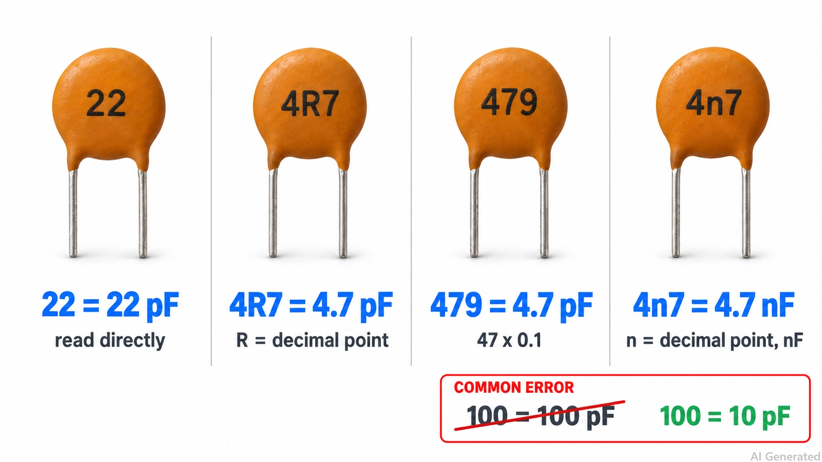
Figure: Small ceramic capacitors marked 22, 4R7, 479, and 4n7 with their decoded values.
Note
In the three-digit system, the code 100 means 10 × 10⁰ = 10 pF, not 100 pF. A 100 pF capacitor is marked 101. If a part carries a plain number with no other context, confirm the value against the datasheet or measure it off the board.
Ceramic Capacitor Tolerance Codes: J, K, M, and More
A letter after the capacitance code gives the tolerance: how far the actual capacitance may differ from the marked value under the manufacturer's test conditions. In 473J, the J means ±5%, so the 47 nF part may measure from 44.65 nF to 49.35 nF.
| Letter | Tolerance | Typical Use |
|---|---|---|
| B | ±0.1 pF | Low-capacitance parts; confirm the series-specific range |
| C | ±0.25 pF | Low-capacitance parts; confirm the series-specific range |
| D | ±0.5 pF | Low-capacitance parts; confirm the series-specific range |
| F | ±1%; confirm alternatives from datasheet | Precision C0G parts |
| G | ±2%; confirm alternatives from datasheet | Precision C0G parts |
| J | ±5% | C0G timing and filter parts |
| K | ±10% | General-purpose X7R and X5R parts |
| M | ±20% | X7R, X5R, and Y5V parts, and safety discs |
| Z | +80% / −20% | Older Y5V and Z5U discs |
B, C, and D are absolute tolerances in picofarads, not percentages. A 4.7 pF part marked C, for example, may measure from 4.45 pF to 4.95 pF.
Ceramic Capacitor Voltage Codes and Ratings
The three-digit capacitance code carries no voltage information. A voltage rating is printed on the body when the part is large enough, usually as a plain value such as 50 V or 1 kV; otherwise, it appears as a two-character voltage code, such as 1H for 50 V, in the part number and on the reel label.
| Voltage Code | Rated Voltage (DC) |
|---|---|
| 0J | 6.3 V |
| 1A | 10 V |
| 1C | 16 V |
| 1E | 25 V |
| 1V | 35 V |
| 1H | 50 V |
| 2A | 100 V |
| 2D | 200 V |
| 2E | 250 V |
| 2G | 400 V |
| 2J | 630 V |
| 3A | 1,000 V |
For example, the 1H in Murata part number GRM188R71H104KA93D indicates a 50 V rating. The same part number also carries R7 for X7R, 104 for 100 nF, and K for ±10%.
These codes are common but not universal. Murata uses YA for 35 V, and Samsung uses single letters, so confirm the code against the datasheet for that series. If the original rating is unknown, take it from the BOM or datasheet, or choose one with a margin above the circuit's highest voltage.
How to Read Full Ceramic Capacitor Marking: Dielectric, Safety, and Examples
A full ceramic capacitor marking combines the capacitance code with a tolerance letter, a voltage rating, and sometimes a dielectric or safety code. Read it field by field: the digits first, then the letter, then any voltage, temperature-characteristic, or safety code.
Dielectric Codes on Ceramic Capacitors
A dielectric code, such as X7R, describes how the capacitance changes with temperature. It is not a tolerance code.
- C0G (NP0): 0 ±30 ppm/°C from −55 °C to +125 °C; Class 1, stable, used for timing and filters.
- X7R: ±15% capacitance change from −55 °C to +125 °C; Class 2, general purpose.
- X5R: ±15% capacitance change from −55 °C to +85 °C; Class 2, common in high-value MLCCs.
- Y5V: +22% / −82% capacitance change from −30 °C to +85 °C; Class 2, high capacitance, low stability.
Class 2 dielectrics, such as X7R and X5R, can also lose a significant portion of their capacitance under DC bias. Check the manufacturer's DC-bias curve at your operating voltage and see how the dielectric classes compare for ceramic capacitors.
Safety Class Codes on Ceramic Capacitors: X1, X2, Y1, and Y2
Mains-rated ceramic discs carry a safety class certified under IEC 60384-14:
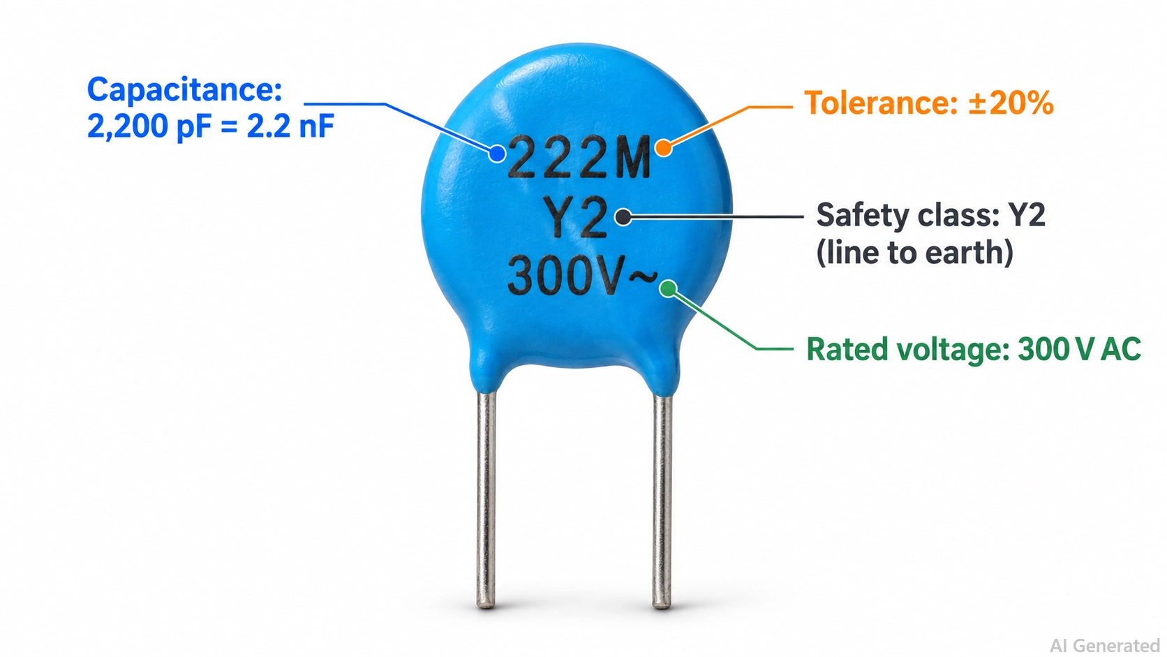
Figure: Y2 safety ceramic disc capacitor marked 222M Y2 300V~ with each marking field labeled.
- X1 and X2: Connected across the line, where a capacitor failure does not create a shock hazard.
- Y1 and Y2: Connected from line to protective earth or across the isolation barrier, where a failure could expose a user to shock. Y1 is rated for reinforced insulation, and Y2 for basic insulation.
When replacing a safety capacitor, use a component with the appropriate X or Y safety classification, an equal or higher rated AC voltage, and the required safety approvals. Do not select a replacement based on voltage rating alone.
Ceramic Capacitor Marking Examples Explained
| Marking | Capacitance | Tolerance | Voltage | Other Information |
|---|---|---|---|---|
| 104 | 100 nF | Not marked | Not marked | Typical of small leaded MLCCs |
| 104K | 100 nF | ±10% | Not marked | Check the datasheet for the voltage |
| 103K 1KV | 10 nF | ±10% | 1 kV DC | High-voltage ceramic disc |
| 2A104J | 100 nF | ±5% | 100 V (2A) | Format is also common on film capacitors |
| 222M Y2 300V~ | 2.2 nF | ±20% | 300 V AC | Y2 safety class |
| GRM188R71H104KA93D | 100 nF | ±10% | 50 V (1H) | X7R, 0603 package, from the reel label |
Ceramic Capacitor with No Code: How to Identify Unmarked SMD MLCCs
Most SMD multilayer ceramic capacitors (MLCCs) in 0402, 0603, and 0805 packages carry no printed code because the ceramic body is too small for legible markings. Identify them from documentation, and measure them when documentation is missing.
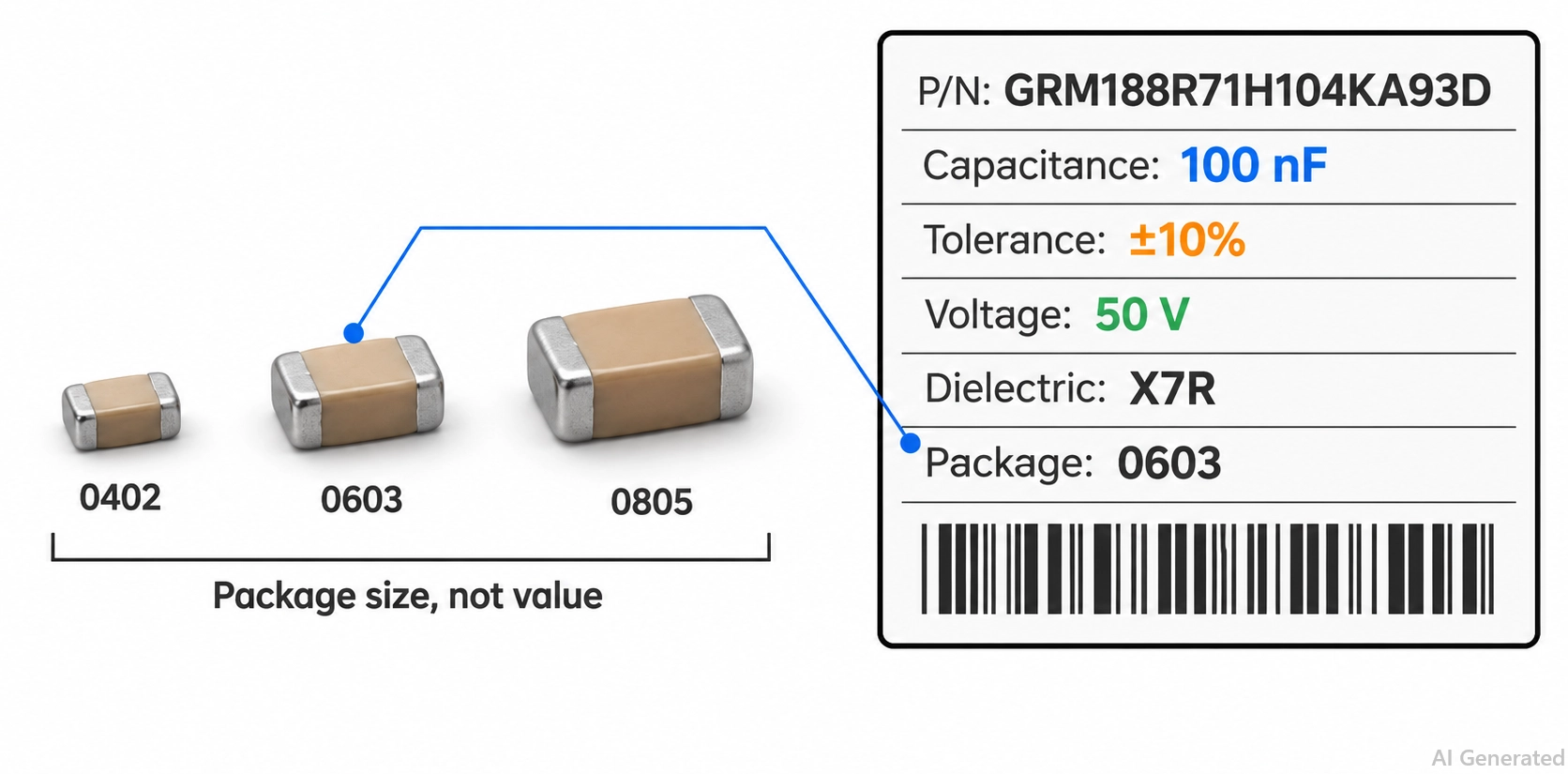
Figure: Unmarked 0402, 0603, and 0805 SMD ceramic capacitors showing value, voltage, and dielectric.
How to Identify an Unmarked SMD MLCC
Use these sources first:
- BOM and schematic: Find the reference designator (e.g., C12) and read the value, voltage, and dielectric from the BOM line.
- Reel or bag label: The manufacturer's part number decodes into capacitance, tolerance, voltage, and dielectric.
A code such as 0402 or 0603 is the package size, not the capacitance. See SMD capacitor sizes for the dimensions of each package. For codes printed on tantalum and other SMD capacitors, see how to read an SMD capacitor code.
How to Measure a Ceramic Capacitor Value
Without documentation, measure the capacitor off the board:
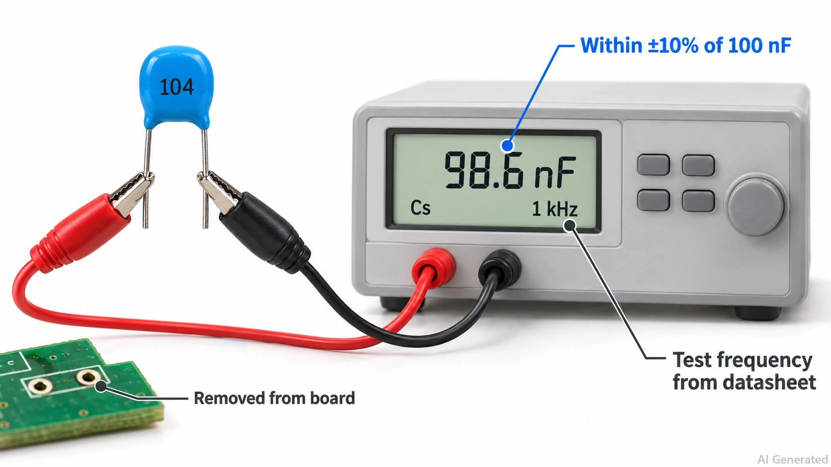
Figure: Ceramic capacitor removed from a PCB and measured on an LCR meter at 1 kHz.
Step 1: Discharge the capacitor. Power the board off, then discharge high-voltage parts through a resistor rather than a direct short.
Step 2: Remove the capacitor. In-circuit readings include parallel components and are often unreliable.
Step 3: Measure with an LCR meter. Use the test frequency and voltage specified in the datasheet, typically 1 kHz for Class 2 parts.
Step 4: Compare with the tolerance. Round the reading to the nearest standard value within the expected tolerance.
A meter reading gives capacitance only; choose the voltage rating and dielectric from the circuit.
Conclusion
Understanding a ceramic capacitor code makes it easier to identify capacitance values and select the correct components. Remember that the first two digits represent the significant figures, while the third is the multiplier. For example, 104 means 100 nF, and 103 means 10 nF.
Always check the tolerance letter, voltage rating, and dielectric type before choosing a replacement. If the capacitor has no printed markings, refer to the BOM, component label, or datasheet to confirm its specifications.
FAQs About Ceramic Capacitor Codes
What Is the Difference Between a 104 and a 105 Capacitor?
A 105 capacitor is ten times larger. A 104 part is 100 nF (0.1 µF), while a 105 part is 1 µF, so they are not interchangeable where the value sets timing or filtering.
Is 0.1 µF the Same as 100 nF?
Yes. 0.1 µF, 100 nF, and 100,000 pF are the same capacitance, and all three correspond to the three-digit code 104.
What Does 104K Mean on a Ceramic Capacitor?
104K means a nominal capacitance of 100 nF with a ±10% tolerance. Under the specified test conditions, its capacitance should fall between 90 nF and 110 nF. The K indicates tolerance, not voltage rating.
Can I Replace a Ceramic Capacitor with a Higher Voltage Rating?
Usually yes. A higher voltage rating is acceptable when the capacitance, tolerance, dielectric, and package match, although the higher-rated part may be physically larger or cost more.
Why Does My 104 Capacitor Measure Less Than 100 nF?
A 104 capacitor may measure below 100 nF because of its tolerance, test conditions (frequency and AC voltage), or aging. For example, a 104K capacitor (±10%) can read as low as 90 nF and still be within specification. Class 2 dielectrics such as X7R and X5R also lose capacitance over time (aging), and in a circuit, DC bias can reduce the effective capacitance further.
Popular Articles
• SMD Resistor Package Sizes: Complete Size Chart, Footprints & How to Choose
• How to Solder SMD Components Like a Pro [2026 Updated]
• SMD Resistor Codes: How to Read 3-Digit, 4-Digit, and EIA-96 Markings
• SMD Capacitor Codes: Identification, Markings, and Polarity
• SMD Capacitor Sizes: Complete Size Chart and Selection Tips for PCB Design and Assembly
Keep Learning
Ceramic Capacitor Code Guide: Values, Tolerance, and Voltage
Key Takeaways Three-Digit Rule: The first two digits represent the significant figures, while the third indicates the power-of-ten multiplier. The resulting capacitance is expressed in picofarads (pF). Common Values: Code 104 represents 100,000 pF (100 nF or 0.1 µF), while 103 represents 10,000 pF (10 nF or 0.01 µF). Tolerance Letters: Letters indicate capacitance tolerance. Common examples include J (±5%), K (±10%), and M (±20%). For small capacitance values, B, C, and D specify tolerances in pF. Vol......
What is a HDMI RF Modulator? A Complete Guide
What is an HDMI RF Modulator? An HDMI RF modulator is a device that converts high-definition multimedia interface (HDMI) signals into Radio frequency (RF) signals. This allows HDMI-compatible devices, such as Blu-ray players, gaming consoles, and streaming devices, to transmit audio and video content over coaxial cables, making them compatible with older television sets or distribution systems that use RF signals. These modulators are particularly useful in settings where legacy TV systems are still i......
SMD Inductor Code: How to Read Inductor Markings and Values
Key Takeaways Three digits are read in µH: 100 is 10 µH and 101 is 100 µH. The third digit is the number of zeros, not part of the value. R and N are decimal points: R in microhenries (4R7 = 4.7 µH), N in nanohenries (2N2 = 2.2 nH). A trailing letter is a tolerance: K is ±10% and M is ±20%. On RF inductors below about 10 nH, C and D mean ±0.2 nH and ±0.5 nH. Most small chip inductors are unmarked: identify them from the BOM or reel label first, then with an LCR meter at the right test frequency. The m......
A Complete Guide to Surface Mount Device (SMD)
Imagine holding a smartphone in your hand. Inside that sleek device lies a complex network of thousands of miniature components — resistors smaller than a grain of rice, capacitors thinner than a fingernail, and integrated circuits containing millions of transistors. Without Surface Mount Technology (SMT) and its compact Surface Mount Devices (SMDs), none of this would exist. Just a few decades ago, electronics were bulky. Radios filled desks, computers filled rooms, and assembling a circuit meant dri......
TSSOP Package Guide: Dimensions, Pitch, Footprint & SMT Soldering
Key Takeaways Lead span, not body width: Build the footprint from the lead span (6.4 mm or 8.1 mm tip to tip), not the 4.4 mm or 6.1 mm body width. MSOP vs TSSOP: Check the width in the drawing before reusing a footprint: MSOP-8 and TSSOP-8 share pitch and body length, and some vendors label a 3.0 mm-wide package TSSOP8. Mask dams: A standard TSSOP footprint leaves a 0.20 mm pad gap: enough for solder mask dams on 1 oz copper, no margin on 2 oz, and no dams on JLCPCB flex boards. Thermal pad: On HTSSO......
Understanding the Role of PCB Controllers in Electronic Design
A PCB Controller is an important part of designing and building electrical systems. It controls the functions of different mechanical parts on a printed circuit board (PCB) and makes sure they can talk to each other easily. People use PCB controllers in a lot of different situations, from home technology to factory automation. The purpose of this article is to discuss the importance of PCB controllers, including the different kinds, their uses, and the best ways to choose and use them. 1. What is a PC......