
Capacitor Value Guide: Charts, Codes, Selection & Practical Uses
15 min
- Capacitor Value Chart
- What Capacitor Value Should I Use? (Quick Answer)
- Understanding Capacitor Values and Capacitor Units
- E12 Capacitor Values
- Common Capacitor Values and Their Uses
- How to Read Capacitor Value
- How to Choose the Right Capacitor Value
- How Capacitor Type Affects Effective Capacitor Value
- Why Your 10µF Capacitor May Not Actually Be 10µF
- Common Capacitor Selection Mistakes
- FAQs about Capacitor Value
- Conclusion
Whether you're adding a 100nF bypass capacitor to a microcontroller, sizing a smoothing capacitor for a power supply, or selecting a capacitor for an RC filter, choosing the wrong value can lead to noise, instability, or poor circuit performance. Capacitor selection is one of the most frequent decision points in hardware engineering, yet finding the right balance between theory and physical constraints is rarely straightforward.
In this guide, you'll learn how capacitor values work, how to read capacitor markings, how to calculate capacitance for common circuits, and how to choose the right capacitor value using practical engineering examples.
Capacitor Value Chart
| Three-Digit Marking Code | Value in picofarads (pF) | Value in nanofarads (nF) | Value in microfarads (µF) |
|---|---|---|---|
| 101 | 100 pF | 0.1 nF | 0.0001 µF |
| 102 | 1,000 pF | 1 nF | 0.001 µF |
| 103 | 10,000 pF | 10 nF | 0.01 µF |
| 104 | 100,000 pF | 100 nF | 0.1 µF |
| 105 | 1,000,000 pF | 1,000 nF | 1.0 µF |
| 473 | 47,000 pF | 47 nF | 0.047 µF |
What Capacitor Value Should I Use? (Quick Answer)
Check the capacitor value reference table
| Circuit Application | Typical Value Range | Primary Capacitor dielectric type | Primary Function |
|---|---|---|---|
| DIigital MCU Decoupling | 100nF | Multi-layer Ceramic (MLCC X7R) | High-frequency noise filtering |
| LDO Voltage Regulator | 1µF to 22µF | Low-ESR Tantalum or Ceramic | Control loop stability |
| Analog Filters | 100pF to 47nF | Ultra-stable C0G / NP0 Ceramic | Signal Frequency Filtering |
| Crystal Oscillator | 12pF to 33pF | High-Precision Ceramic Disc / SMD | Clock frequency tuning |
| Power Supply Smoothing | 470µF to 4700µF | Radial Aluminum Electrolytic | AC mains ripple smoothing |
| Audio Coupling | 1µF to 10µF | Film or Polyester Cap | DC blocking and signal pass |
Note
As a general rule, always start with the component datasheet recommendation, then verify capacitance, voltage rating, ESR, and package size.
Understanding Capacitor Values and Capacitor Units
A capacitor value, or capacitance (C), measures a component's electrical characteristic to store an electrostatic charge (Q) per unit of potential difference (V).
This fundamental relationship is governed by the physics formula Q = C × V.
The fundamental unit of capacitance is the Farad (F). Because a one-Farad capacitor stores an exceptionally large volume of charge, practical PCB designs use smaller sub-units: microfarads (µF), nanofarads (nF), and picofarads (pF).
- 1 µF = 10-6 F
- 1 nF = 10-9 F
- 1 pF = 10-12 F
Manufacturers do not produce parts in random increments. Instead, components are grouped into standardized sets of values called preferred number series.
The most common of these is the E12 series, which divides a decade into 12 logarithmic steps: 10, 12, 15, 18, 22, 27, 33, 39, 47, 56, 68, and 82.
Understanding pF, nF, and uF
Choosing the right unit category corresponds directly to the target frequency domain of your circuit.
Picofarad-range components are selected for radio-frequency (RF) impedance-matching networks, LC filters, and clock crystal tuning.
Nanofarad-range components are used for digital IC bypass networks and high-frequency noise suppression.
Microfarad-range components serve as local power-storage reservoirs, linear-regulator output stabilizers, and power-rail ripple-smoothing filters.
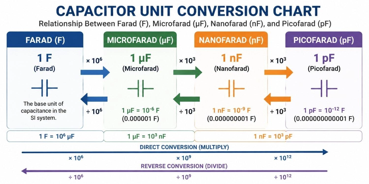
Figure: Capacitor unit conversion chart displaying relationships between Farads, microfarads (µF), nanofarads (nF), and picofarads (pF).
E12 Capacitor Values
| Multiplier Class | Standard E12 Logarithmic Numerical Bases | Typical Hardware Application Domain |
|---|---|---|
| Common picofarads (pF) Range | 10, 12, 15, 18, 22, 27, 33, 39, 47, 56, 68, 82 | Crystal Oscillators, RF impedance matching, high-frequency tuning |
| Common nanofarads (nF) Range | 1.0, 1.2, 1.5, 1.8, 2.2, 2.7, 3.3, 3.9, 4.7, 5.6, 6.8, 8.2, 10, 22, 47, 100, 220, 470 | Digital IC bypass, high-frequency noise suppression, and analog filters |
| Common microfarads (µF) Range | 1.0, 2.2, 3.3, 4.7, 10, 22, 47, 100, 220, 470, 1000, 2200, 4700 | DC-DC buck output filters, LDO stability, power rail bulk smoothing |
Common Capacitor Values and Their Uses
Selecting specific standard values keeps production moving smoothly. The table below details the most common capacitor values found across real-world circuit designs:
| Value | Typical Intended Use Case | Dominant Hardware Selection Context |
|---|---|---|
| 22pF | Crystal Load Balancing | Microcontroller system clock stability networks |
| 100nF | Local IC decoupling | High-frequency digital noise suppression per supply pin |
| 10µF | Linear Regulator Output | LDO stability and high-frequency transient recovery |
| 10 µF | Bulk decoupling | Mid-frequency noise suppression on local DC power rails |
| 100 µF | Buck Converters | Output ripple filtering on buck and boost regulators |
| 1000 µF | Low-Frequency Smoothing | Suppressing heavy voltage ripple after the AC bridge rectifiers |
22pF Capacitors
Almost every modern microcontroller uses an external quartz crystal oscillator to generate its system clock. These crystals need precisely matched load capacitors (typically between 12pF and 33pF, with 22pF being the most common) to vibrate at the correct frequency. If the load capacitance value is too low, the clock runs too fast; if it is too high, the oscillator might fail to start up.
100nF Capacitors
This is the most widely used capacitor value in digital electronics. Housed in small surface-mount devices like 0402 or 0603 footprints, 100nF ceramic capacitors feature an exceptionally high self-resonant frequency. This makes them highly effective at absorbing fast, high-frequency digital switching noise that would otherwise interfere with the IC's logic states.
1uF and 10uF Capacitors
These values represent the transition point between high-frequency noise bypass and bulk charge storage. They are usually placed at the output of linear drop-out (LDO) regulators to keep the internal feedback loop stable and to handle transient current demands from downstream loads during sudden processing steps.
100uF and 1000uF Capacitors
These bulk values are predominantly aluminum electrolytic or polymer capacitors. Due to their large physical size and higher internal parasitics, they cannot filter high-frequency noise, but they are highly effective as low-frequency bulk reservoirs that smooth out AC voltage ripple in power supplies or power heavy switching loads like DC motor drives.
How to Read Capacitor Value
Surface Mount Device (SMD) ceramic caps and small radial disc capacitors use a three-digit marking code system where the baseline unit is always picofarads (pF).
The first two digits represent the significant figures of the value, and the third digit represents the multiplier (the number of zeros to append).
Suffix letters indicate the tolerance rating (J = ±5%, K = ±10%, M = ±20%).
For help identifying tiny SMD components, review the guide to read SMD capacitor codes directly.
Understanding the 3-Digit Capacitor Code
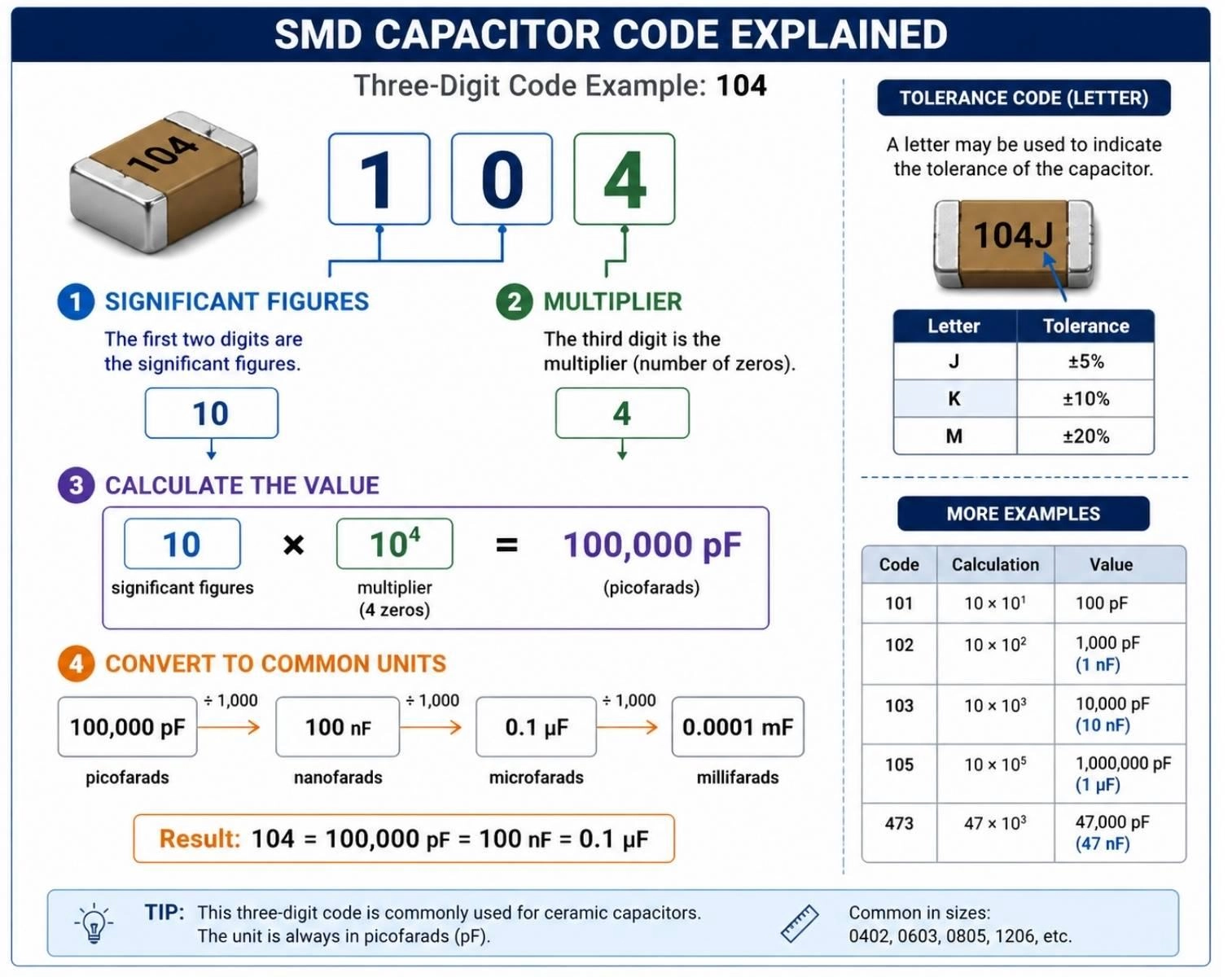
Figure: Showing a three-digit SMD capacitor marking code converting to nanorad units.
Capacitor Tolerance Markings
A fourth letter is often printed next to the three-digit code to signify manufacturing tolerances.
Class I ceramic components (like C0G/NP0 dielectrics used in precision timing) typically display a 'J' (±5%) tolerance stamp.
Class II decoupling ceramics (like X7R used in bypass paths) commonly feature 'K' (±10%) or 'M' (±20%) markings, which are perfectly acceptable for bulk rail smoothing where exact capacitance values are not critical.
How to Choose the Right Capacitor Value
Capacitor selection is not based on capacitance alone. Engineers must also consider voltage rating, dielectric type, ESR, tolerance, package size, and operating temperature. There is no universal capacitor value. The correct value depends completely on the circuit function in your schematic.
Engineering Tip: For digital circuits, 100nF is often recommended as a starting point for decoupling, but always verify capacitor values against the IC manufacturer's datasheet because power requirements vary significantly between devices.
Decoupling Capacitor (STM32 Microcontroller Example)
Digital microcontrollers draw current in brief, aggressive bursts corresponding to their system clock speed. A decoupling capacitor acts as a local high-frequency battery, suppressing noise before it spreads through the power grid.
For standard microcontrollers like the STM32, placing a dedicated 100 nF ceramic capacitor immediately adjacent to every VDD pin is mandatory. Additionally, the main power entry trace requires a shared bulk 4.7uF-10uF tantalum or ceramic capacitor to handle low-frequency transient load swings.
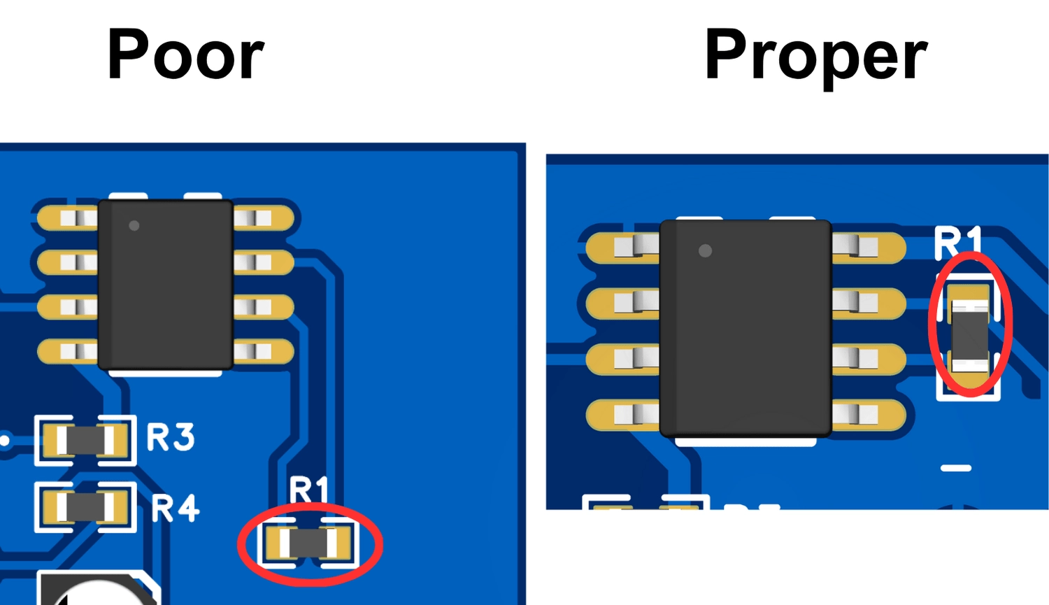
Figure: Showing high-frequency decoupling capacitor placement adjacent to active component pins.]
Voltage Regulators (AMS1117 LDO Example)
The datasheet for the common AMS1117 Linear Regulator specifies a 10µF input capacitor to counter the parasitic inductance of upstream power wiring. For output stability and clean load transient recovery, it mandates a minimum 10µF low-ESR Tantalum or aluminum electrolytic capacitor. Mismatching the ESR can trigger severe voltage oscillations in the control loop.
Buck Converters
High-frequency step-down Buck Converters demand low-ESR input capacitors, such as a pair of 10µF or 22µF X7R ceramic caps, to handle high RMS ripple currents. The output filter requires a combined 22µF to 100µF low-ESR ceramic or polymer capacitor network to keep output voltage ripple minimal and maintain control loop stability.
Power Supply Filtering
To calculate the bulk filter capacitance needed to keep the power supply output ripple voltage below a specific threshold, use the ripple equation:
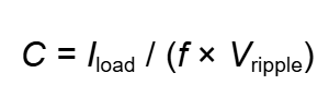
Where I_load is the continuous load current in Amperes, f is the post-rectification frequency (such as 100 Hz for a 50 Hz full-wave rectified transformer), and V_ripple is the maximum allowable peak-to-peak voltage ripple.
- Example: For a 12V DC linear power supply delivering 1.0 A with a maximum allowable peak-to-peak ripple of 2.0 V over a 100 Hz full-wave rectified bridge, the calculation is: C = 1.0 / (100 × 2.0) = 0.005 F = 5,000 µF
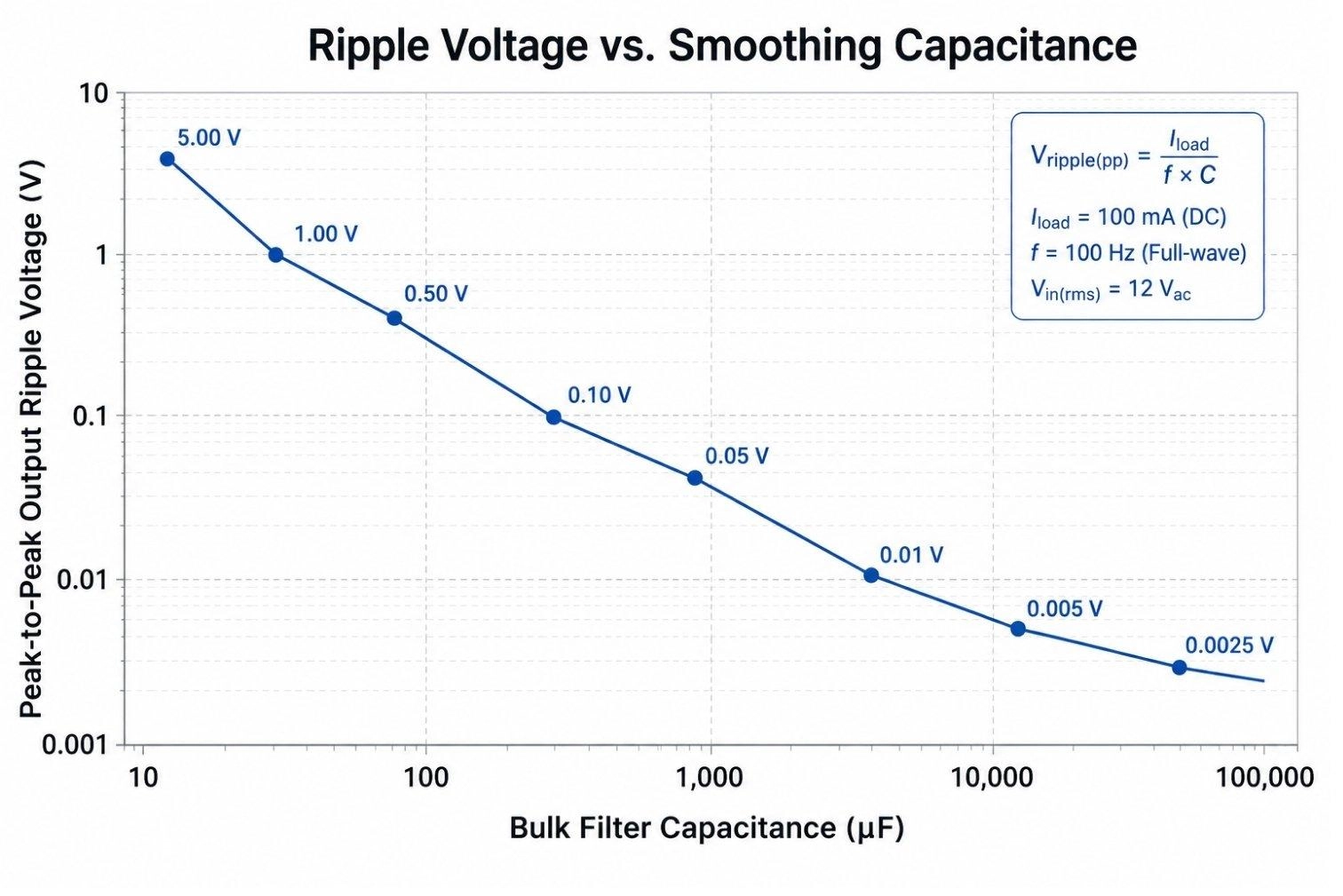
Figure: Illustrating peak-to-peak voltage ripple reduction as bulk filter capacitance increases.
RC Timing
To calculate the time delay (tau) of a basic resistor-capacitor charging network, use the time constant equation:

Where tau is time in seconds to reach 63.2% of the total supply charge, R is resistance in Ohms, and C is capacitance in Farads.
- Example: If you pair a 100 kOhm pull-up resistor with a 10µF capacitor to create an automated hardware power-on reset delay, your time constant is: τ = 100,000 × (10 × 10-6) = 1.0 seconds
Filters
To find the exact -3 dB cutoff frequency (fc) of a passive single-order RC filter network, use the standard cutoff formula:
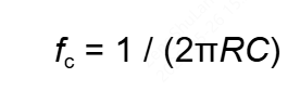
- Example: If you need to strip out high-frequency sensor noise above 15 kHz using a fixed 1 kOhm series resistor, rearrange the formula to find the necessary capacitor value: C = 1 / (2 × π × 1000 × 15000) = 10.61 nF Adjust this calculated value to match the nearest standard E12 series size, which is a 10nF ceramic capacitor.
After selecting capacitor values, upload your PCB files to JLCPCB for automated DFM analysis, real-time quoting, and full PCB assembly services.
Get Quote Now >
How Capacitor Type Affects Effective Capacitor Value
A common trap is assuming that any two capacitors with identical microfarads (µF) ratings will behave the same way in a circuit. Component construction materials introduce unique physical trade-offs that drastically alter real-world circuit performance.
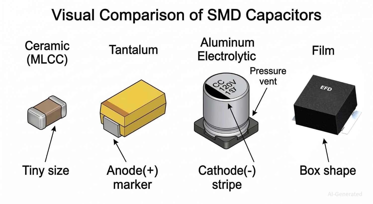
Figure: Main types of SMD capacitors: Ceramic (MLCC), Tantalum, Aluminum Electrolytic, and Film
Multi-layer Ceramic Capacitor (MLCC)
Offers exceptionally low Equivalent Series Resistance (ESR) and Equivalent Series Inductance (ESL). However, it has lower voltage-to-volume efficiency and suffers from significant capacitance loss under DC bias conditions. It is best suited for local high-frequency decoupling.
Aluminum Electrolytic Capacitor
Provides excellent bulk capacitance-per-volume density at a low cost. On the downside, it has high internal ESR and higher leakage currents, and its liquid electrolyte can dry out over time. It is primarily used for low-frequency power supply filtering.
Tantalum Capacitor
Delivers stable bulk capacitance in a compact footprint with low ESR and excellent temperature stability. Crucially, Tantalum capacitors can fail catastrophically by short-circuiting or catching fire if exposed to voltage spikes above their rated limits. Take note of the voltage margins outlined in the JLCPCB capacitor polarity guide when working with polarized packages.
Film Capacitors
Film capacitors use thin plastic films (such as polyester, polypropylene, or polycarbonate) as their dielectric. They are non-polarized, physically robust, and offer excellent parameter stability over temperature and time. With exceptionally low dielectric absorption, low leakage current, and high peak-current handling capabilities, they are highly favored in audio signal path coupling, precision analog timing circuits, AC power line filters, and industrial snubber networks, though they are physically larger than ceramic options of equivalent value.
Why Your 10µF Capacitor May Not Actually Be 10µF
One of the most surprising issues with Class II ceramic capacitors (like X5R and X7R) is their susceptibility to DC Bias Dependency.
When a continuous DC voltage is applied across a ceramic capacitor, its internal ferroelectric crystalline structure undergoes partial polarization lock. This structural shift drastically reduces its active capacitance.
Understanding DC Bias Effects of Capacitor
| Nominal Listed Capacitor Value | Dielectric Class | Maximum DC Voltage Rating | Active DC Operating Bias Voltage | Real Functional Capacitance Value |
|---|---|---|---|---|
| 10 µF | X5R Ceramic | 6.3 V | 5.0 V Applied Bias | 3.8 µF (62% value loss) |
| 10 µF | X7R Ceramic | 25 V | 5.0 V Applied Bias | 8.4 µF (16% value loss) |
| 10 µF | Tantalum | 16 V | 12.0 V Applied Bias | 10.0 µF (0% value loss) |
How to Reduce Capacitance Loss
To prevent DC bias loss from compromising your circuit, pick a ceramic capacitor with a voltage rating significantly higher (at least 2x to 3x) than your actual operating rail.
Alternatively, you can allocate larger footprints (such as 0805 or 1206 instead of 0402) because physically larger case sizes preserve active capacitance much better under DC load.
Common Capacitor Selection Mistakes
- Ignoring MLCC DC Bias Dependency: Selecting a ceramic capacitor based solely on its nominal value without accounting for capacitance drop under voltage.
- Using Aluminum Electrolytics for High-Frequency Filtering: High internal ESL renders electrolytic capacitors useless for filtering fast digital logic switch noise above a few Megahertz.
- Choosing Odd, Non-Standard Values: Specifying non-standard values drives up sourcing costs and slows down automated pick-and-place assembly lines. Standardizing on common parts optimizes your bill-of-materials (BOM).
- Neglecting Footprint Sizing Availability: Choosing a value and voltage combination that forces you to use a massive component size that overcomplicates footprint optimization. For clean layout implementation rules, refer to the SMT solder pad design guide.
FAQs about Capacitor Value
Q: What capacitor value should I use?
Your target value depends on the application. Use 100nF for local digital IC power pin decoupling, 10µF to 47µF for linear voltage regulator loops, and use explicit filter formulas for analog signal lines.
Q: Is higher capacitance better?
No. Larger capacitors provide more bulk energy storage but typically introduce higher parasitic inductance (ESL) and lower self-resonant frequencies. This reduces their ability to filter high-frequency noise.
Q: Can I replace a 10µF capacitor with a 100µF value?
In basic low-frequency power supply smoothing networks, yes. However, in switching regulators or sensitive LDO feedback circuits, this change can alter loop stability and cause voltage oscillations.
Q: Why is the 100nF capacitor value so common?
It strikes an optimal balance between low parasitic inductance (ESL) and enough energy capacity to suppress high-frequency switching noise in common 3.3V and 5V digital circuits.
Q: Why does my 10µF capacitor measure less than 10µF?
This is usually caused by DC Bias Dependency effects in ceramic capacitors, which polarize the internal dielectric structure and drop active capacitance, or testing at an AC frequency that doesn't match the component's rated test specifications.
Q: Can I use a higher voltage rating capacitor?
Yes. A capacitor's voltage rating is its maximum safe operating limit. Using a higher voltage capacitor provides an excellent safety margin and reduces DC Bias Dependency capacitance drops in ceramic components.
Q: What happens if my circuit capacitance is too low?
Insufficient capacitance leads to poor noise filtering, power rail voltage drops during logic steps, control loop instability, and shifted cutoff frequencies in analog filters.
Q: What is the value of a capacitor labeled 102?
A Capacitor labeled with code “102” has a value of 1,000 pF (picofarads), which is equal to 1 nf (nanofarads) or 0.001 uF (microfarads). The code decodes to 10 followed by 2 zeros.
Q: What does 104 mean on a capacitor?
The code “104” means 100,000 pf (picofarads). This converts directly to 100 nF (nanofarads) or 0.1 uF (microfarads). It is the most common bypass and decoupling capacitor value used in modern digital circuits.
Q: What is the difference between uF and nF?
The difference is scale. One microfarads(uF) is equal to 1,000 nanofarads(nf). To convert uF to nF, multiply by 1,000 (e.g., 0.1uF = 100nF). To convert nF to uF, divide the value by 1,000.
Conclusion
There is no single "correct" capacitor value for every circuit. The best choice depends on whether the capacitor is used for decoupling, filtering, timing, coupling, or energy storage.
Successfully choosing a capacitor value requires analyzing the circuit function first and the physical limitations of the component second. Balancing nominal capacitance against DC bias loss, equivalent series resistance (ESR), and voltage rating keeps your power rails quiet and your control loops stable.
By designing with standard E12 series values and understanding your target operational frequencies, you will build more robust hardware and avoid common PCB design mistakes.
Popular Articles
• SMD Capacitor Sizes: Complete Size Chart and Selection Tips for PCB Design and Assembly
• SMD Diode Code Lookup: Full List, Marking Guide & Identification [2026 Guide]
• SMD Resistor Package Sizes: Complete Size Chart, Footprints & How to Choose
• SMD Capacitor Codes: Identification, Markings, and Polarity
• How to Solder SMD Components Like a Pro [2026 Updated]
Keep Learning
Thin Film vs. Thick Film Resistors: Key Differences, Advantages & Applications
Key Takeaways Default to thick film resistors for most designs. They are cost-effective, robust, and ideal for pull-ups, LED current-limiting, digital circuits, and surge-prone applications. Choose thin-film resistors whenever a resistor defines an analog quantity, such as a voltage divider, reference network, gain-setting circuit, or current-sensing signal chain. Their tight tolerance and low TCR help maintain measurement accuracy over temperature and time. Most PCB designs use thick film or thin fil......
What Is the ESP32? A Complete Guide to Features, Architecture, Modules, Programming, and Applications
From Wi-Fi-enabled temperature sensors and wearable health monitors to industrial gateways and AI-powered cameras, the ESP32 microcontroller has become one of the world's most widely adopted wireless embedded platforms. Combining a powerful processor with integrated Wi-Fi and Bluetooth, it lets engineers build connected devices without separate networking hardware. This guide covers ESP32 specifications, architecture, the full family of variants, development boards, programming tools, and real-world E......
How to Choose the Right STM32 Microcontroller: Compare Series, Cortex-M Cores, and Key Features
STMicroelectronics ships thousands of STM32 MCU part numbers across more than a dozen series, and that variety is exactly what makes STM32 microcontroller selection difficult. Pick the wrong family, and you pay for it later: oversized BOM cost, wasted power budget, or a board respin when a peripheral turns out to be missing. This STM32 microcontroller selection guide breaks the decision into a five-step framework built on practical engineering criteria, not datasheet marketing copy, so you can match a......
SMD Transistor Code Lookup: Identify Markings, Pinout & Multimeter Test Guide
Repairing a circuit board often brings a familiar frustration: staring at a tiny, three-legged black component with an obscure two- or three-letter code. Whether troubleshooting a bare prototype or a mass-produced PCBA, knowing how to quickly decode these surface-mount device (SMD) markings is an essential skill for any electronics engineer or repair technician. In this comprehensive guide, you will learn: 1. How to decode SMD transistor marking codes 2. How to identify BJT vs MOSFET types 3. How to f......
SMD Capacitor Sizes: Complete Size Chart and Selection Tips for PCB Design and Assembly
In the world of modern electronics, surface mount devices (SMDs) have revolutionized board design, allowing for smaller, faster, and more efficient printed circuit boards. When designing a PCB, selecting the correct SMD capacitor sizes is one of the most critical decisions an engineer must make to ensure both electrical reliability and manufacturability. In this article, you will find practical, authoritative guidance on: Comprehensive SMD capacitor size charts for quick reference. How to read imperia......
SMD Diode Code Lookup: Full List, Marking Guide & Identification [2026 Guide]
In modern electronics, surface-mount diodes are used everywhere - from power input protection circuits to high-speed signal routing. Because these components are extremely small, manufacturers cannot print full part numbers on their bodies. Instead, they use short marking codes such as A2, M7, SS14, or SL, which often confuse beginners during PCB repair, reverse engineering, or component replacement. This guide explains how to decode SMD diode codes, identify polarity, test components using a multimet......