How Engineers Choose Capacitor Voltage Ratings for PCB Circuits
13 min
- Capacitor Voltage Ratings Table at a Glance
- How to Choose the Right Capacitor Voltage Rating
- Can I Use a Higher Voltage Capacitor?
- Effect of Capacitor Voltage Rating on MLCC Capacitance (DC Bias Effect)
- Capacitor Voltage Rating Selection by Application
- Choosing the Right Capacitor Voltage for Common Power Rails
- Common Capacitor Voltage Ratings and Their Uses
- Common Mistakes When Choosing Capacitor Voltage Ratings
- FAQs
- Conclusion
Choosing a capacitor's voltage rating looks trivial on a schematic, but it quietly drives reliability, board size, and BOM cost. Pick too low, and the cap fails. Pick too high carelessly, and you waste space and (for MLCCs) may still lose capacitance you didn't know you had. Balancing these factors is critical for successful hardware development.
In this guide, you will learn:
- How to apply voltage derating (the 1.5x and 2x rules)
- How to select the right rating for 3.3 V, 5 V, 12 V, 24 V, and 48 V rails
- Why higher-rated capacitors often deliver better real-world performance
Capacitor Voltage Ratings Table at a Glance
What capacitor voltage rating should I use? Here is the quick answer:
| Circuit Voltage | Typical Capacitor Voltage Rating | Recommended Voltage Rating | Example Applications |
|---|---|---|---|
| 3.3 V | 6.3 V - 10 V | 10 V | STMM32/ ESP32 Decoupling (3.3v) |
| 5 V | 10 V - 16 V | 16 V | 5V Rail (USB Power, Logic) |
| 12 V | 25 V | 25 V | 12V Rail (Buck Converter/LED) |
| 24 V | 35 V - 50 V | 50 V | 24V Industrial Rail |
| 48 V | 63 V - 100 V | 100 V | 48V POE/ Telecom |
Quick Rule
Use a capacitor voltage rating at least 1.5x-2x higher than the highest voltage the circuit will experience, including startup surges and transient spikes, then round up to the next standard value (6.3 V, 10 V, 16 V, 25 V, 35 V, 50 V, 63 V, 100 V).
How to Choose the Right Capacitor Voltage Rating
Step 1: Determine Maximum Operating Voltage
Identify the worst-case continuous voltage, not just the nominal rail:
- 3.3 V rail from an LDO can ride to 3.45 V during transients
- 5 V USB rail is spec'd at 4.75-5.25 V, with upstream noise pushing it higher
- 12 V rail from a buck converter can overshoot to 13-14 V at startup
Step 2: Apply Voltage Derating
| Capacitor Type | Recommended Derating | Equivalent Rule |
|---|---|---|
| Ceramic (X7R / X5R) | 80% of VR | ~1.25x rail |
| Aluminum electrolytic | 80% of VR (commercial); 50% for long life | 1.25x-2x rail |
| Tantalum (MnO2) | 50% of VR | 2x rail |
| Polymer tantalum/ niobium oxide | 80% of VR | ~1.25x rail |
| Film (AC service) | 50-60% of VR | 1.67-2x rail |
| Actual Rail Voltage | Recommended Voltage Rating |
|---|---|
| 3.3 V | 6.3 V - 10 V |
| 5 V | 10 V - 16 V |
| 12 V | 25 V |
| 24 V | 50 V |
The 1.5x rule is a quick mental check for ceramics and electrolytics. The 2x rule applies strictly to MnO2 tantalums and any node exposed to highly inductive transients.
Step 3: Consider Voltage Spikes and Transients
- Relay coils/ solenoids: switching a 12 V relay without a flyback diode produces reverse spikes of 50-150 V
- DC motors: similar inductive kickback plus continuous brush noise
- Automotive (ISO 7637-2 / ISO 16750-2 load dump): an unclamped 12 V alternator load-dump pulse reaches ~100 V; centralized suppression still limits spikes to 35 V on a 12 V system and 58 V on a 24 V system, which is well above nominal
For these noisy nodes, clamp the transients with a TVS diode or MOV upstream and size the capacitor to the clamped voltage.
Step 4: Verify Datasheet Requirements
- AMS1117: recommends a 22 uF tantalum on the output for stability; the input absolute maximum is 15 V, meaning the input cap should be rated >= 25 V when feeding from a 12 V supply.
- STM32 (AN4488): requires one 100 nF X7R bypass capacitor per VDD pin placed within a few millimeters of the pin, plus one 4.7-10 uF bulk capacitor per supply group. These act as local decoupling components. ST recommends at least 2x the rail voltage for the bypass capacitor voltage rating.
- LM7805 / 78xx: datasheet calls for 0.33 uF on the input and 0.1 uF on the output, ceramic, close to the pins; bulk 10-100 uF electrolytic upstream when the source is far.
- Buck converters (e.g., AP1507): Diodes Inc. app note specifies an input cap rated at ~1.5x maximum input voltage, and an output cap at >=1.5x output voltage.
Can I Use a Higher Voltage Capacitor?
Yes, and it is usually beneficial. Substituting a higher-rated cap of the exact same capacitance and dielectric type is electrically safe in almost all cases.
Benefits of Higher Voltage Ratings (Reliability & Effective Capacitance)
- More reliability margin: operates at a smaller fraction of its maximum rated voltage
- Lower leakage current from reduced electrical stress
- Better effective capacitance on MLCCs (explained next)
Tradeoffs: Size, Cost, and Lower Capacitance Density
- Larger physical package size
- Higher component cost (10 V → 50 V ceramics are typically 2-4x more expensive)
- Lower capacitance density in the same footprint
| Replacement | Safe? |
|---|---|
| 10 V → 16 V | Yes |
| 16 V → 25 V | Yes |
| 25 V → 50 V | Usually (verify footprint, ESR for switching apps) |
| 50 V → 100 V | Usually (size grows) |
Effect of Capacitor Voltage Rating on MLCC Capacitance (DC Bias Effect)
It is the most common hidden cause of circuit instability on assembled boards.
The MLCC DC Bias Effect Explained (Capacitance Loss at DC Voltage)
Class II ceramics (X5R, X7R, Y5V) use ferroelectric barium-titanate dielectrics. When you apply a DC voltage across these materials, it polarizes and saturates the crystal domains, reducing the effective permittivity and therefore the effective capacitance. The closer the bias voltage gets to the rated voltage, the worse this loss becomes.
Class I (C0G / NP0) dielectrics are non-ferroelectric and essentially immune, though they are limited to low values (<=100 nF) in small SMD packages.
How DC Bias Reduces Effective Capacitance (Real Measurement Data)
A 10 uF 6.3 V X5R 0805 biased at 5 V shows approximately -60% capacitance loss due to the DC bias effect, leaving you with roughly 4 uF of effective capacitance (Murata manufacturer data, cited via passive-components.eu). The loss spread between different manufacturers for equivalent X7R parts ranges from -35% to -65% at rated voltage.
| Capacitor | Operating Bias | Effective Capacitance |
|---|---|---|
| 10 uF 6.3 V X5R (0805) | 3.3 V | ~5-7 uF (~50-70% retention) |
| 10 uF 6.3 V X5R (0805) | 5 V | ~4 uF (~40% retention) |
| 10 uF 25 V X7R (1206) | 5 V | ~8.5-9.5 uF (~85-95% retention) |
| 10 uF 25 V X7R (1206) | 12 V | ~7 uF (~70% retention) |
The Fix
Use a 10 uF 25 V X7R instead of a 10 uF 10 V X5R on a 5 V rail. The 25 V part retains ~85-95% of its capacitance at 5 V.
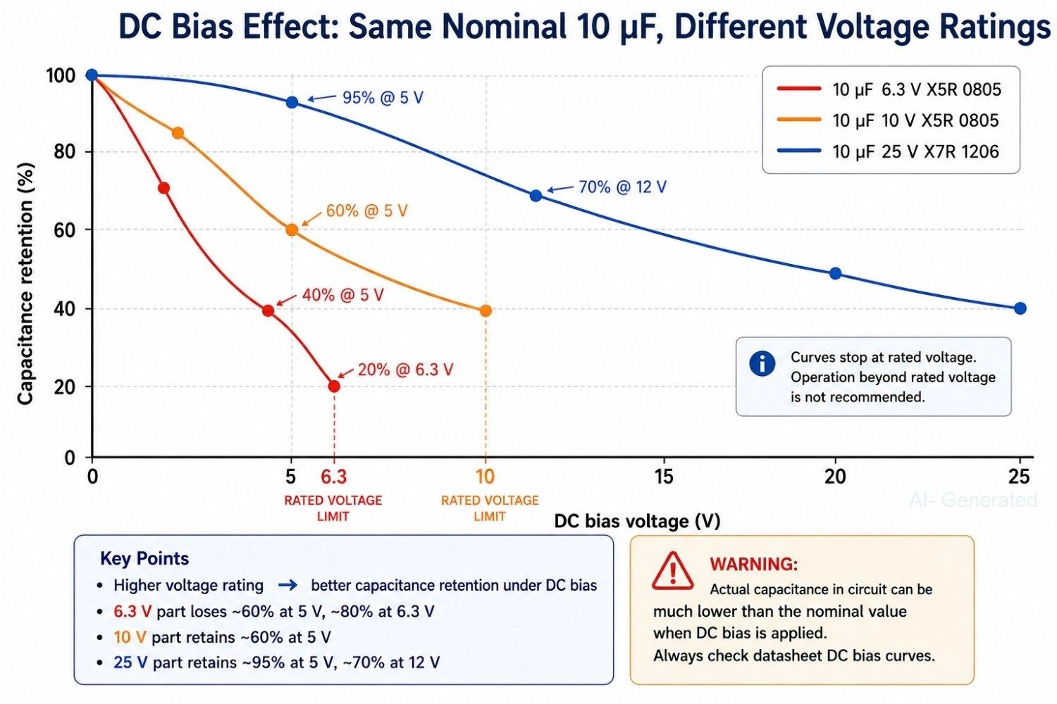
Figure: DC bias curves comparing capacitance retention vs applied voltage for 10 uF MLCCs at 6.3V X5R, 10V X5R, and 25V X7R ratings, showing higher-voltage parts preserve significantly more effective capacitance.
Capacitor Voltage Rating Selection by Application
Microcontrollers (STM32, ESP32, RP2040)
Running on 3.3 V. Standard: 100 nF X7R per VDD pin, 10 V rated, plus 4.7-10 uF bulk per supply group.
A 6.3 V cap has zero derating margin and suffers severe DC-bias loss. Default to 10 V or 16 V ceramics.
Linear Regulators (AMS1117, LM7805)
Size the input cap to the input rail:
- AMS1117-3.3 fed from 12 V → input cap rated >= 25 V
- Output cap on 3.3 V output → 10 V or 16 V
Buck Converters
Input caps see full input voltage plus significant high-frequency switching ripple.
For a 12 V → 5 V buck: 25 V X7R on the input, and 10 V or 16 V X7R on the output. Always follow the converter datasheet for minimum capacitance and ESR requirements.
Power Supplies
- 5 V rails → 10-16 V caps
- 12 V rails → 25 V caps
- 24 V rails → 50 V caps with TVS if exposed
Motor and Relay Circuits
Always assume inductive kickback. Minimum 2x the rail voltage.
On a 12 V relay rail: 25-35 V caps plus a flyback diode placed as close to the coil as possible.
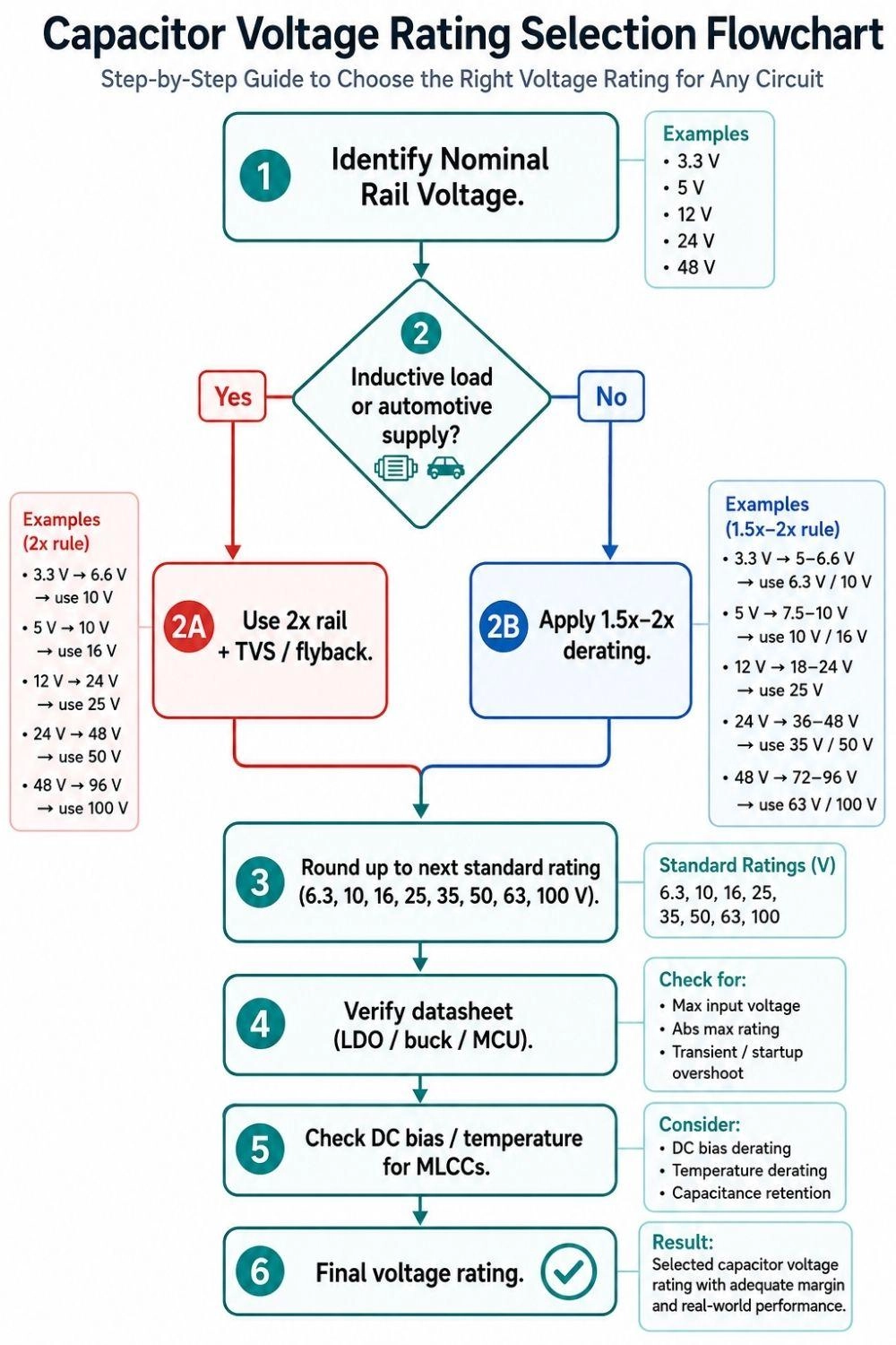
Figure: Decision flowchart for selecting a capacitor voltage rating
Choosing the Right Capacitor Voltage for Common Power Rails
3.3 V Rail: 6.3 V or 10 V?
Use 10 V. A 6.3 V cap on a 3.3 V rail has less than 2x safety margin, and at 3.3 V, an X5R 6.3 V cap may already lose 30-50% of its nominal capacitance to DC bias. The 10 V part is the same physical size in most common values and costs a fraction of a cent more. Default to 10 V; use 16 V for tantalums and safety-critical lines.
5 V Rail: 10 V or 16 V?
Either works electrically, but 16 V is highly preferred. A 10 V cap on a 5 V rail sits exactly at 50% of rated voltage (which is acceptable), but a 16 V cap sits at 31%, giving far better capacitance retention on X7R parts (typically 90%+ versus 60-70% for 10 V X5R at 5 V). For bulk electrolytics on a 5 V supply, 10 V is the bare minimum; 16 V is the safer default.
12 V Rail: 16 V or 25 V?
Use 25 V, not 16 V. A 12 V rail frequently overshoots to 13-14 V during startup transients. A 16 V cap operating at 14 V is running at 87.5% of its rated voltage, exceeding the 80% safe derating threshold. A 25 V cap at 14 V sits comfortably at 56%, well inside safety margins. This distinction matters especially for output bulk filtering on 12 V buck converters.
24 V Rail: 35 V or 50 V?
Use 50 V. A 24 V rail with any inductive switching can easily spike to 28-30 V. A 35 V cap at 30 V is at 86% of its rated voltage with no meaningful margin left. A 50 V cap at 30 V sits at 60%, well within the safe operating range. For 24 V industrial circuits with relay or solenoid switching, use 50 V minimum (63 V or 100 V if transient clamps are absent).
Common Capacitor Voltage Ratings and Their Uses
| Voltage Rating | Typical Applications |
|---|---|
| 6.3 V | Tight-space decoupling on 3.3 V rails (use with caution due to DC bias risk) |
| 10 V | 3.3 V and 5 V logic, MCU decoupling, LDO outputs |
| 16 V | 5 V circuits, USB devices, sensor modules |
| 25 V | 12 V power rails, buck converter inputs, automotive 12 V with TVS |
| 35 V | 24 V industrial logic, 12 V rails with extra margin |
| 50 V | 24 V systems, industrial electronics, snubbers, audio coupling |
| 63 V - 100 V | 48 V telecom / PoE, LED drivers, power electronics |
| >= 200 V | Off-line SMPS, motor drives, EV traction inverters |
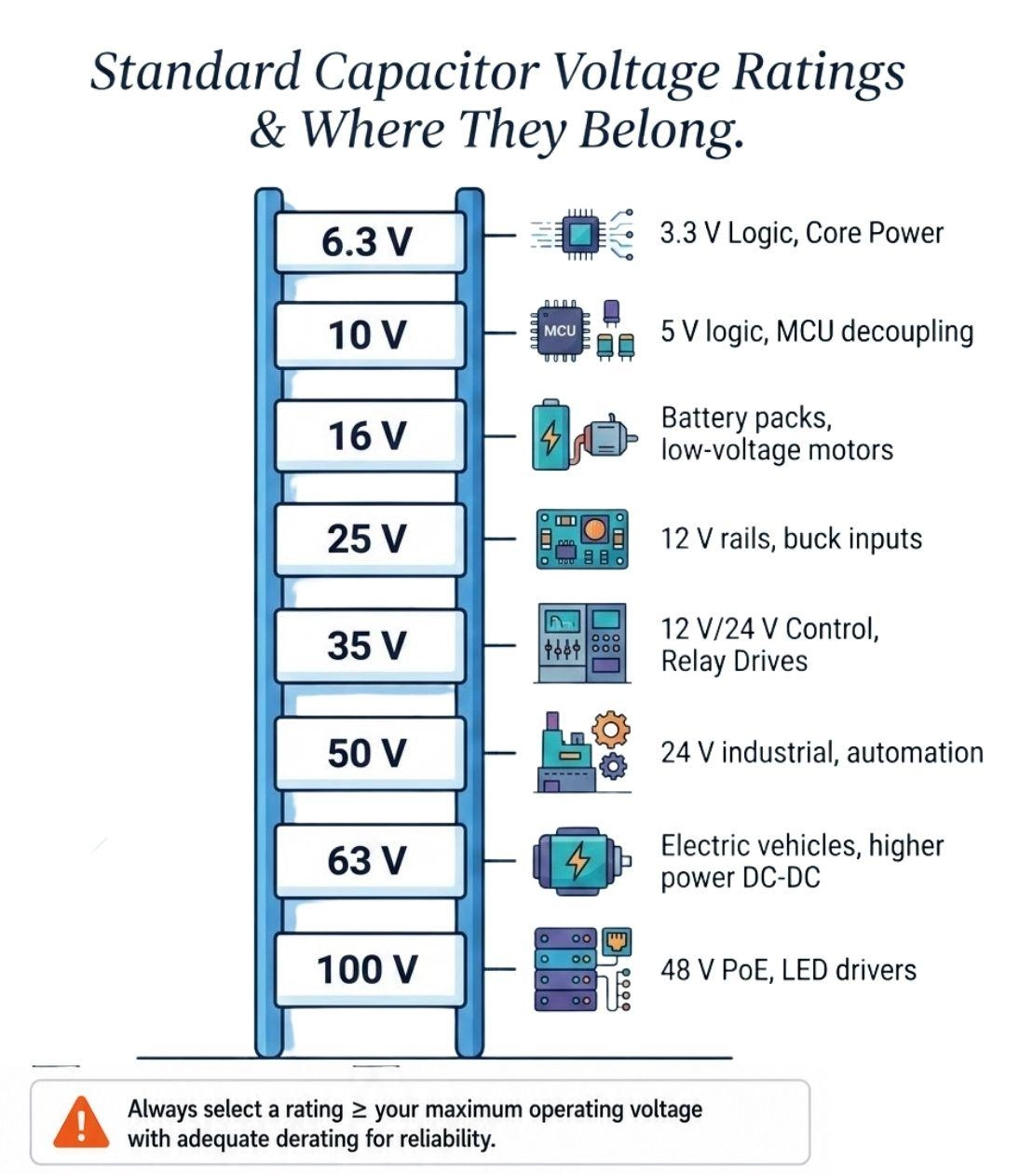
Figure: Standard capacitor voltage ratings from 6.3 V to 100 V with typical PCB application.
Common Mistakes When Choosing Capacitor Voltage Ratings
Matching Supply Voltage Exactly
A 5 V cap on a 5 V rail is the most common beginner mistake. It leaves zero margin for ripple, overshoot, or a supply rail variation to 5.25 V. A 5 V rail needs a 10 V or 16 V cap, never a 5 V or 6.3 V part.
Ignoring Startup Surges
Bulk capacitors on unregulated AC-DC rails and battery-supplied designs see their highest voltage at startup under light load. Always size your components to that peak voltage, not the steady-state nominal run voltage.
Ignoring MLCC DC Bias
Spec'ing a 10 uF 6.3 V X5R for a 5 V decoupling position and expecting 10 uF of actual capacitance is the single most common power-integrity error in PCB design. Refer to the MLCC section above to ensure you avoid this pitfall.
Oversizing Everything
Reflexively jumping three or four voltage steps (such as using a 100 V cap on a 3.3 V rail) wastes board area, complicates routing, and dramatically increases BOM costs. Use standard derating rules to find the perfect middle ground.
Ignoring the Datasheets of the Capacitor
Some LDOs require minimum capacitance and specific ESR (equivalent series resistance) ranges. Low quiescent-current (Low-IQ) LDOs occasionally become unstable or oscillate with too-low-ESR ceramics on the output. Always read the regulator's stability section before finalizing component selection.
Sourcing note: Consolidating your design around one or two common voltage ratings (typically 16 V and 50 V for general-purpose boards) simplifies procurement and SMT assembly. JLCPCB's massive in-stock parts library carries extensive inventory at 10 V, 16 V, 25 V, and 50 V, reducing reel changes and lowering assembly setup costs.

- When you are ready to move from design to production, you can instantly upload your Gerber and BOM files to the Quotation Page to receive an immediate estimate.
- JLCPCB provides state-of-the-art raw PCB fabrication alongside seamless PCB Assembly services for both rapid prototypes and large production builds.
FAQs
Q: How does AC ripple voltage impact DC capacitor voltage selection?
Peak DC voltage plus peak AC ripple voltage must never exceed the rated DC voltage. High ripple currents also generate internal heat; select low-ESR capacitors rated 1.5x to 2x higher than the combined peak voltage to manage thermal stress.
Q: Why do larger MLCC package sizes (like 1206 vs 0402) have better DC bias stability?
At identical ratings, physically larger capacitors have thicker internal dielectric layers. This reduces the internal electric field intensity (V/um) at a given bias voltage, preventing barium-titanate saturation and preserving capacitance.
Q: How does ambient temperature affect aluminum electrolytic capacitor life?
Operating life doubles for every 10 C drop in temperature. High voltage stress accelerates this by increasing leakage currents and internal self-heating, which hastens electrolyte dry-out. Derating to 50-80% protects the capacitor in hot environments.
Q: What are the risks of replacing a tantalum capacitor with a ceramic capacitor?
MLCCs have extremely low ESR. Many older regulators (like LDOs) rely on a capacitor's higher ESR to stabilize their feedback loops. Substituting an MLCC can cause high-frequency oscillation unless a small series resistor is added.
Q: What is the difference between working voltage (WVDC) and dielectric withstanding voltage (DWV)?
WVDC is the maximum continuous DC voltage a capacitor can safely handle over its lifetime. DWV is a short-term, factory-test voltage (often 1.5x to 2.5x WVDC) applied for seconds to identify manufacturing voids or cracks.
Conclusion
A capacitor's voltage rating is just as important as its capacitance value. Selecting the right rating improves reliability, reduces electrical stress, and prevents unexpected failures. Apply appropriate derating (1.5x-2x for ceramics and electrolytics, 2x for MnO2 tantalums), account for startup surges and inductive transients, and always verify the component requirements in the device's datasheet.
Popular Articles
• SMD Resistor Package Sizes: Complete Size Chart, Footprints & How to Choose
• How to Solder SMD Components Like a Pro [2026 Updated]
• SMD Resistor Codes: How to Read 3-Digit, 4-Digit, and EIA-96 Markings
• SMD Capacitor Codes: Identification, Markings, and Polarity
• SMD Capacitor Sizes: Complete Size Chart and Selection Tips for PCB Design and Assembly
Keep Learning
SMD MOSFET Code Guide: How to Identify, Test and Replace a MOSFET
Figure: AO3400A (C20917) in the JLCPCB parts library. The listing gives RDS(on) at 2.5 V gate drive, the number that matters in the replacement example later in this guide. An SMD MOSFET code is the two or three characters printed on top of the package, and on its own it rarely tells you which part you're holding. SMD resistors follow standard marking schemes, such as three- and four-digit codes and EIA-96. MOSFETs don't. The same short code can appear on unrelated parts from different manufacturers, ......
ESP8266 vs ESP32: Which One Should You Use?
Key Takeaways ESP32: Dual-core 240 MHz CPU, Bluetooth Classic and BLE, 520 KB SRAM, and up to 34 GPIOs. ESP8266: Single-core CPU, no Bluetooth, and around 50 KB of free RAM for applications. Lifecycle status: Espressif marks the ESP8266 Not Recommended for New Designs (NRND) and names the ESP32-C2 (ESP8684) as its upgrade, although the ESP8266 remains in production with a longevity commitment. Which ESP32 to use: Choose the ESP32-C2 for simple Wi-Fi or Bluetooth LE firmware, the ESP32-C3 for more memo......
What Is a Thermistor? A Practical Guide to NTC, PTC, Applications, and Circuit Design
Key Takeaways Definition: A thermistor is a thermally sensitive resistor whose resistance changes markedly and predictably with temperature, typically by about 4.4% per °C for a standard 10 kΩ NTC (B25/50 = 3950 K) near 25 °C. NTC vs. PTC: An NTC thermistor's resistance falls as temperature rises, which suits temperature sensing and inrush current limiting; a switching PTC's resistance rises steeply above its switch temperature, which suits circuit protection. Key Specifications: An NTC thermistor is ......
What Is the ESP32-CAM, and How to Wire, Power, and Program It?
Key Takeaways Board, not chip: The ESP32-CAM is an AI-Thinker development board, not an Espressif product. It carries AI-Thinker's ESP32-S module, an OV2640 camera, PSRAM, a microSD slot, and a flash LED. No USB port: The board has no USB connector or USB-to-UART bridge, so you program it via its serial pins using a 3.3 V USB-to-serial adapter, with GPIO0 held low at reset. Few free pins: The camera, PSRAM, and microSD card occupy most GPIOs. With the microSD card unused, GPIO2, GPIO4, GPIO12, GPIO13,......
ESP32 Versions: Which One Should You Use for Your Project?
Key Takeaways Radios decide first: ESP32 versions differ mainly in their radios, CPU cores, and peripherals. Common defaults: The ESP32-C3 suits low-cost Wi-Fi and Bluetooth LE, the ESP32-S3 suits camera, display, voice, and on-device AI. Original ESP32: The chip is still in production and remains the choice for Bluetooth Classic. Versions without Wi-Fi: The ESP32-H2 targets battery-powered Thread and Zigbee devices. Chip, module, or board: Prototype on a development board, then design a module onto y......
SOIC Package: A Complete Guide to Specifications, Types, Uses, and SMT Assembly
As designs transition from legacy through-hole components to high-density Surface Mount Technology (SMT), the Small Outline Integrated Circuit (SOIC) remains the industry standard for operational amplifiers, flash memory, sensors, and microcontrollers. It reflects a well-balanced engineering design, offering a practical compromise between the miniaturisation demanded by modern consumer electronics and the ruggedness required for industrial applications. In this guide, you will learn: SOIC package dime......