Altium MCP: AI PCB Design with GPT-6 and Codex [Step-by-Step Guide]
20 min
- What Is Altium MCP and How Does It Work?
- The Altium MCP Server We Chose and What It Can Do
- How to Connect GPT-6 in Codex to Altium MCP
- The Project: A BL0942 Energy Meter for 230 VAC and 10 A
- Step 1: Let the AI Choose the Components
- Step 2: How the BL0942 Schematic Is Connected
- Step 3: How the AI Placed the Components
- Step 4: How the AI Routed the PCB
- Step 5: Verification and the Fabrication Files Altium MCP Produced
- Altium MCP Accuracy: Where the Engineer Still Had to Step In
- GPT-6 vs. Claude for Altium MCP: Why Computer Use Mattered
- Conclusion
- FAQs About Altium MCP
Altium MCP connects Altium Designer to an AI assistant through a Model Context Protocol (MCP) server, so the AI calls Altium's own scripting functions instead of clicking through screenshots. We tested it with GPT-6 in Codex and the open-source eda-agent server on a 230 VAC, 10 A BL0942 energy-metering board, from datasheet to DRC-clean fabrication files.
The AI chose the parts, drew the schematic, and placed, routed, and checked the board. The circuit decisions, the placement reference, and the corrections stayed with the engineer.
In this guide, you will learn:
- How Altium MCP and the eda-agent server work
- How to connect GPT-6 in Codex to Altium and check the link
- How the AI chose the parts, drew the schematic, and placed and routed the board
- What it exported, and where the engineer still had to correct it
Note
These servers are independent third-party open-source projects. JLCPCB and Altium do not make, own, review, endorse, or support them, and are not responsible for loss or damage to designs, files, computers, or shared information. This article is for educational purposes only.
Before installing one, check its documentation for the data it accesses and shares and what it can do, and review its code, license, security policy, and open issues.
What Is Altium MCP and How Does It Work?
Altium MCP is an MCP server that exposes Altium Designer's scripting functions as tool calls an AI client can request. The AI requests an operation, such as listing nets or placing tracks, and the server executes it in Altium and returns a structured result.
No AI model runs inside Altium Designer. The model runs in the AI client, and the data path to the live design has four layers:
| Layer | What It Does | In Our Test |
|---|---|---|
| AI client | Runs the model and sends tool calls over stdio | Codex running GPT-6 |
| MCP server | Translates tool calls into bridge commands | eda-agent 0.8.1 (Python) |
| Workspace | Passes request and response files between both sides | A local folder in the user profile |
| Altium-side script | A DelphiScript polling loop that runs each command on the open documents | Altium Designer 26.11.1.5 |
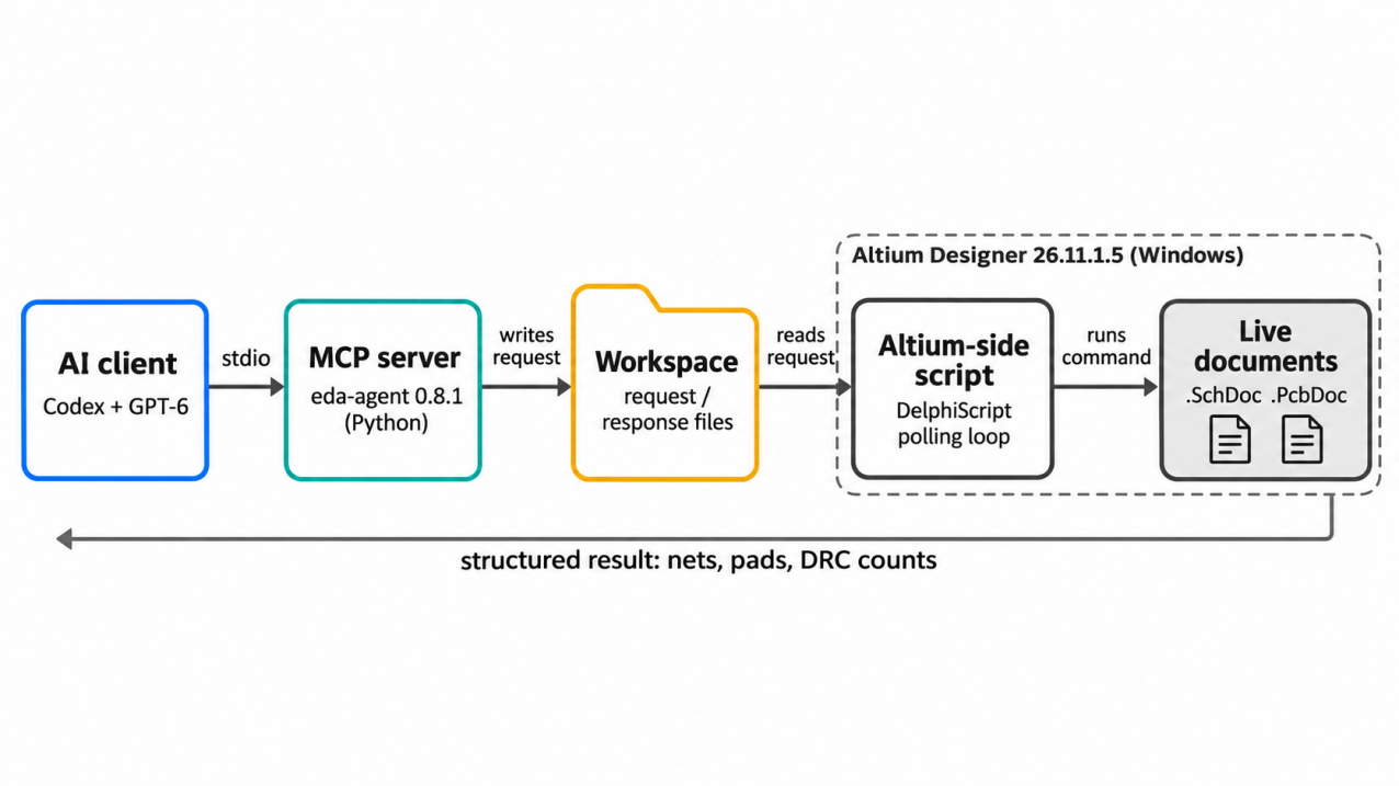
Figure: Altium MCP data path from Codex and GPT-6 to the live Altium documents.
Altium MCP vs. Computer Use
A computer-use agent clicks and types on the screen, then reads a new screenshot. Altium MCP returns structured data instead, such as a net list or a DRC count.
We chose MCP to save tokens: a short text reply should carry the answer in fewer tokens than a screenshot the model must interpret.
The Altium MCP Server We Chose and What It Can Do
We used eda-agent, an Apache-2.0 open-source Altium MCP server by salitronic. Its README describes around 600 Altium tools over a persistent DelphiScript bridge and marks the project as experimental.
What eda-agent can do in Altium:
- Libraries: create schematic symbols and PCB footprints in a project library
- Schematics: place parts, wires, and net labels, then read the compiled netlist back
- PCB: place components, tracks, vias, and copper pours, and start the autorouter
- Checks: run native DRC and ERC and return each violation as data
- Outputs: generate fabrication files through an Altium output job (OutJob)
- Controls: a read-only mode and a UI-automation fallback that you can turn off
- Other EDA tools: KiCad and EasyEDA Pro backends
Other Altium MCP Servers
There is no official Altium MCP server yet. The Altium developer portal lists "MCP Server for Altium Designer" and "MCP Server for Altium 365" as Coming Soon, checked on November 2, 2026. Other third-party options include:
| Server | Needs Altium Open | What It Does | License |
|---|---|---|---|
| altium-mcp (coffeenmusic) | Yes | Symbols, footprints, design queries, and output jobs | MIT |
| Altium-MCP-Suite | Yes | Edits schematics, PCBs, and libraries; packaged for Codex | MIT |
| altium-designer-mcp | No | Edits .PcbLib and .SchLib files offline | GPL-3.0 |
| altium-monkey-mcp | No | Read-only schematic, netlist, BOM, and PCB inspection | AGPL-3.0 |
Note
The MCP servers discussed in this article are independent, third-party open-source projects. Neither JLCPCB nor Altium develops, owns, reviews, endorses, or supports these tools. They are not responsible for any loss or damage involving your designs, files, computer, or shared data. This article is for educational purposes only.
How to Connect GPT-6 in Codex to Altium MCP
Install eda-agent on the Windows PC that runs Altium Designer, register it in Codex, start the bridge in Altium, and confirm the link with read-only queries. Back up the project first.
Install and Register the Altium MCP Server
eda-agent needs Windows, Python 3.11 or later, and a recent Altium Designer, with AD20 or later preferred:
|
|---|
Register it as a local stdio server in ~/.codex/config.toml, pointing to your Python executable. Codex needs the --headless flag:
|
|---|
The easy way: after you have reviewed the repository, give its GitHub link to Codex and ask it to set up the environment. Codex follows the README, installs the Python package, and copies the Altium scripts.
Start the Bridge and Check the Connection
- Open Preferences → Scripting System → Global Projects, click Install, and select Altium_API.PrjScr. Older versions label this menu DXP → Preferences.
-
Open File → Run Script, expand Dispatcher.pas, and run StartMCPServer. The EDA Agent MCP status window opens.
- Ask the AI to run app_ping, then to list the open documents and the active document.
- Check the request counter in the status window. In our first test, six read requests completed.
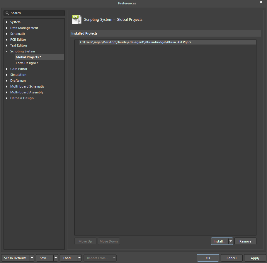
Figure: Altium Preferences showing the eda-agent Altium_API.PrjScr script project under Global Projects.
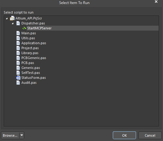
Figure: Altium Run Script dialog with Dispatcher.pas and the StartMCPServer procedure selected.
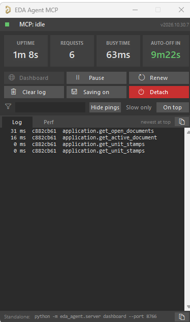
Figure: EDA Agent MCP status window after six read requests from the AI client.
Note
The polling loop stops itself after 10 minutes with no commands and no keep-alive pings from the MCP client. If tool calls start to time out, run StartMCPServer again.
Model and Token Use in Our GPT-6 Run
The design ran on GPT-6.1 Sol, the GPT-6 model we used in Codex, at high reasoning effort. Finding and vetting the MCP servers used GPT-6.1 Terra, which was also high effort.
| Session | Model | Tokens |
|---|---|---|
| Server search, vetting, and setup | GPT-6.1 Terra | About 7 M |
| Components, schematic, placement, routing, and checks | GPT-6.1 Sol | About 92 M |
| Compaction to 80 × 64 mm and fabrication files | GPT-6.1 Sol | 9.85 M in about 30 minutes |
The board used about 102 M tokens. In the main session, about 98% of the input tokens were cached, because each MCP turn re-sends the conversation and the tool schemas. Cached tokens count far more cheaply than new input. Output in the main session was only 422 K tokens, 236 K of them reasoning.
The Project: A BL0942 Energy Meter for 230 VAC and 10 A
We had built a similar energy-metering project before, around a lower-accuracy metering IC. This time we wanted better measurement on a properly designed PCB, so we selected the Belling BL0942 (TSSOP-14) before the AI started. Belling specifies the BL0942 for 10 mA to 30 A with a 1 mΩ shunt, and under 1% gain error without calibration when the external components meet its conditions.
What the board does:
- Measures a single-phase 230 VAC load of up to 10 A continuous
- Reports voltage, current, active power, and energy over UART to an external MCU
- Outputs energy pulses on CF1 and a zero-crossing signal on ZX
- Runs from an external 5 V supply through an isolated DC/DC converter
The board has not been fabricated, assembled, or powered. Every result in this guide is a CAD result.
Step 1: Let the AI Choose the Components
We asked GPT-6 to choose the components before drawing anything, and gave it three inputs:
- The reference circuit: a picture of the BL0942 reference application circuit
- The shunt: a Yezhan ASR-M-3-1F, 1 mΩ, LCSC C469427, which we had already chosen
- An application summary: a mains energy meter for a 10 A load that talks to an MCU
Without this picture, an earlier and shorter brief left out the shunt and the mains divider.
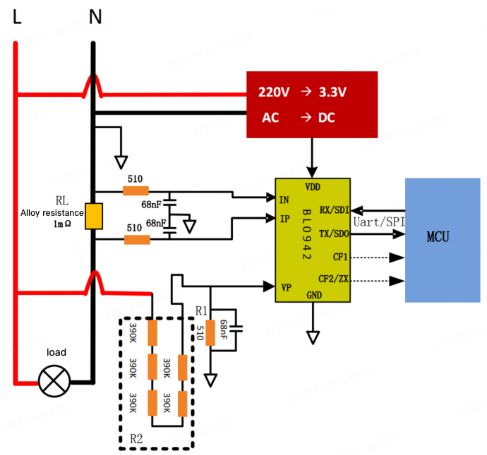
Figure: BL0942 reference application circuit from the datasheet, given to the AI with the application summary.
Before drawing, the AI asked about the load current, the power source, and the MCU connection. We answered: 10 A continuous, keep the external isolated 5 V input with an AMS1117-3.3, and an isolated MCU interface. It then returned this parts list:
| Function | Selected Part | Key Value |
|---|---|---|
| Metering IC | Belling BL0942-TSSOP14L | UART output |
| Current shunt | Yezhan ASR-M-3-1F | 1 mΩ, 1%, 5 W, 2512 |
| Voltage divider | 5 × YAGEO RV1206FR-07390KL | 390 kΩ, 1%, high voltage |
| Filter resistors | 3 × YAGEO RT0805BRD07510RL | 510 Ω, 0.1% |
| Filter capacitors | 3 × KEMET C1206C683J5GACTU | 68 nF, C0G, 50 V |
| Isolated DC/DC | RECOM R05CT05S-R | 5 V to 5 V, 500 mW, reinforced |
| Regulator | AMS1117-3.3 | 3.3 V meter supply |
| Surge protection | Littelfuse TMOV14RP275E | 275 VAC thermal MOV |
| Terminals | Phoenix Contact 1731721 | 7.62 mm pitch, 24 A |
Every proposed part still needs engineering review before acceptance. Component availability should also be verified before layout. You can use the JLCPCB Parts Library to check part numbers, stock, and assembly availability before approving the BOM.
Step 2: How the BL0942 Schematic Is Connected
The AI drew the circuit on two sheets in Altium through MCP: the mains meter and the isolated power and UART interface.
Sheet 1: Mains Input, Current Sensing, and Voltage Sensing
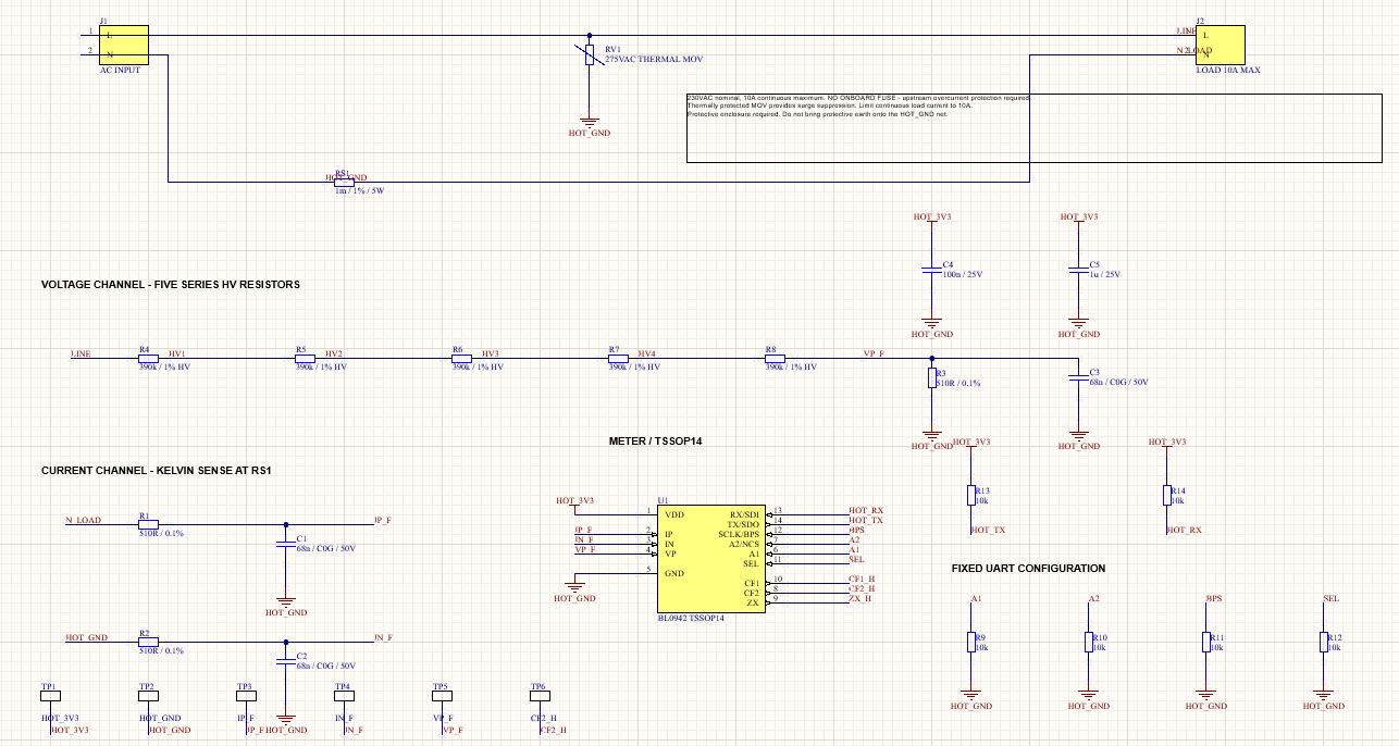
Figure: Mains meter schematic sheet with the shunt, voltage divider, input filters, and BL0942.
- Mains path: the line runs straight from J1 to the load terminal J2 (10 A maximum). With no onboard fuse, upstream overcurrent protection is required.
- Surge protection: RV1, a 275 VAC thermally protected MOV, is installed between the line and HOT_GND.
- Current shunt: RS1 (1 mΩ, 1%, 5 W) sits in the neutral return between HOT_GND and N_LOAD. At 10 A, it develops 10 mV and dissipates 0.1 W.
- Current channel: R1 (510 Ω, 0.1%) and C1 (68 nF, C0G) filter the N_LOAD side into IP_F, and R2 and C2 filter the HOT_GND side into IN_F. Both are Kelvin taps at RS1.
- Voltage channel: five 390 kΩ resistors in series (R4 to R8) run from LINE to VP_F, over R3 (510 Ω) and C3 (68 nF) to HOT_GND. The five parts share the mains voltage.
- BL0942 (U1): VDD takes HOT_3V3 with C4 (100 nF) and C5 (1 µF). CF1, CF2, ZX, RX, and TX leave as HOT-side nets for J4.
- Fixed UART setup: 10 kΩ pull-downs on A1, A2, BPS, and SEL (R9 to R12) select UART mode, address 0, and 4800 bps. R13 and R14 pull TX and RX up to 3.3 V, as the datasheet requires.
- Test points: TP1 to TP6 sit on HOT_3V3, HOT_GND, IP_F, IN_F, VP_F, and CF2_H.
The divider ratio is 510 / (1,950,000 + 510), about 1/3,825. At 230 VAC, VP sees about 60 mV RMS, and at 253 VAC (230 V + 10%) about 66 mV RMS.
Both fit the BL0942's 70 mV RMS voltage-channel range, with little headroom at high line. The shunt's 10 mV sits well inside the 30 mV RMS current-channel range. Because the C0G capacitors have a 5% tolerance, the BOM requires C1-C3 to be matched to within 1%.
Sheet 2: Isolated Power and the HOT UART Header
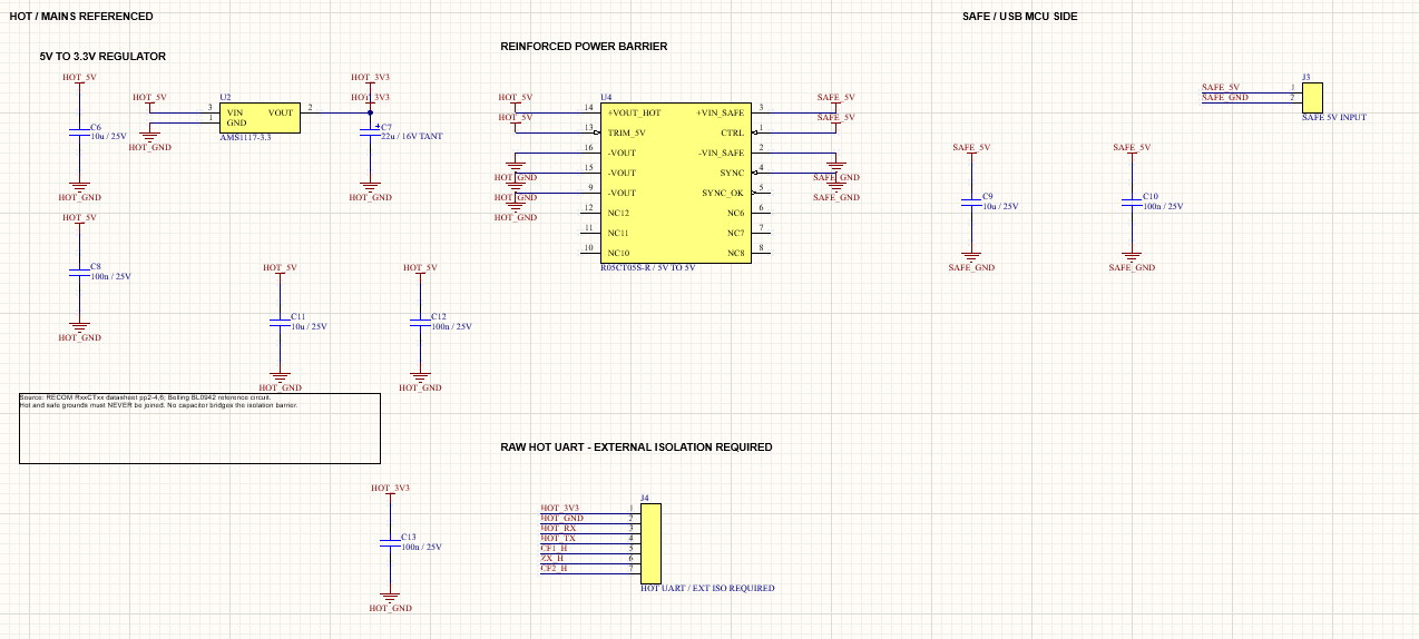
Figure: Power and interface schematic sheet with the isolated DC/DC converter, regulator, and HOT UART header.
- Safe input: J3, "SAFE 5V INPUT", brings SAFE_5V and SAFE_GND in from the MCU side.
- Isolated converter: U4, a RECOM R05CT05S-R, turns SAFE_5V into HOT_5V across a reinforced barrier, with C9 and C10 on its safe side and C11 and C12 on its HOT side. Seven unused pins stay open.
- Regulator: U2, an AMS1117-3.3, converts HOT_5V to HOT_3V3, with C6 (10 µF) and C8 (100 nF) on the input and C7 (22 µF tantalum) on the output.
- Isolation rule: a sheet note states, "Hot and safe grounds must NEVER be joined. No capacitor bridges the isolation barrier."
- J4, raw HOT UART: seven pins carry HOT_3V3, HOT_GND, HOT_RX, HOT_TX, CF1_H, ZX_H, and CF2_H, with C13 (100 nF) on HOT_3V3.
The UART is referenced to HOT_GND, the mains neutral, so every J4 pin must be treated as hazardous mains potential. The converter isolates only the power, so the MCU must connect through an external isolated UART adapter.
The Fuse and Isolator the AI Added That We Removed
The AI's first mains schematic added an onboard fuse (F1) and an ISO7741 digital isolator (U3) with its own decoupling. After reviewing the first placement, we removed both:
- Fuse: the line now runs directly from input to load, the MOV stays, and the board calls for upstream overcurrent protection.
- Isolator: the AI asked whether to remove only the ISO7741 or the DC/DC converter too. We kept the converter and moved signal isolation to an external isolated UART adapter.
Step 3: How the AI Placed the Components
GPT-6 placed every component through Altium MCP, but its first placement ignored the current path and the isolation boundary. After we gave it a placement reference, it produced a placement we could route. Without that human input, it could not yet reach one on its own.
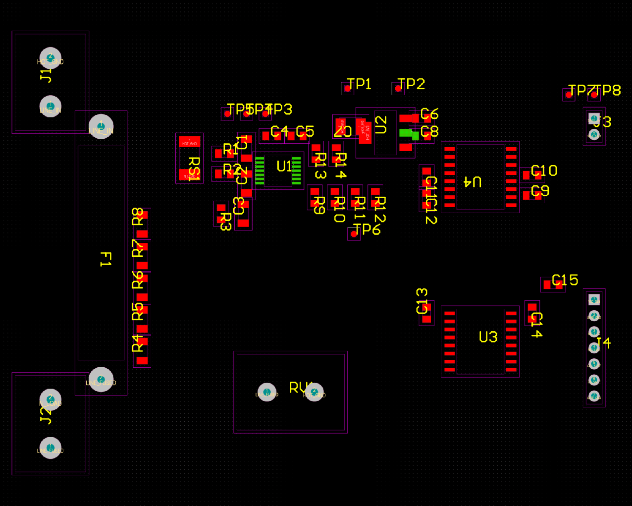
Figure: First AI placement of the BL0942 board with fuse F1 and isolator U3 still fitted.
What was wrong with the first placement:
- Parts were spread across the board instead of following the current path. The MOV sat away from the AC terminals, and the UART header sat far from the meter IC.
- There was no defined boundary between the mains-referenced parts and the safe 5 V input.
The placement reference we gave:
- Keep the AC input and load terminals on one edge.
- Follow the current path, with the shunt and divider between the terminals.
- Keep the BL0942 and its filters close to the shunt.
- Put the isolated 5 V input on the far side of an isolation barrier under the converter.
With that reference, the AI regrouped the board: the AC terminals on one edge, the shunt and divider between them, the BL0942 beside the shunt, and the isolated 5 V input on the far side of the isolation barrier under the converter.
Step 4: How the AI Routed the PCB
GPT-6 routed the board in Altium MCP, prioritizing the high-current and sensing paths.
- Route critical paths first: the 10 A current path uses 6 mm copper narrowing to 4.4 mm near the terminals, on 70 µm (2 oz) copper. Kelvin sense traces leave the inner edges of the shunt pads, so they carry no load current.
- Hold the isolation gap: an 8 mm HOT_COLD clearance rule separates the mains-referenced side from the isolated input. It is a CAD constraint, not a claim of insulation compliance.
- Complete the remaining connections: the autorouter completed 57.8% of the routing, leaving 35 connections. The AI routed the rest through MCP with explicit track coordinates.
- Finish and check: the AI added separate bottom-layer ground pours for the HOT and SAFE sides, stitching vias, and silkscreen labels such as "NO ONBOARD FUSE". It then ran native DRC and fixed the reported violations until none remained.
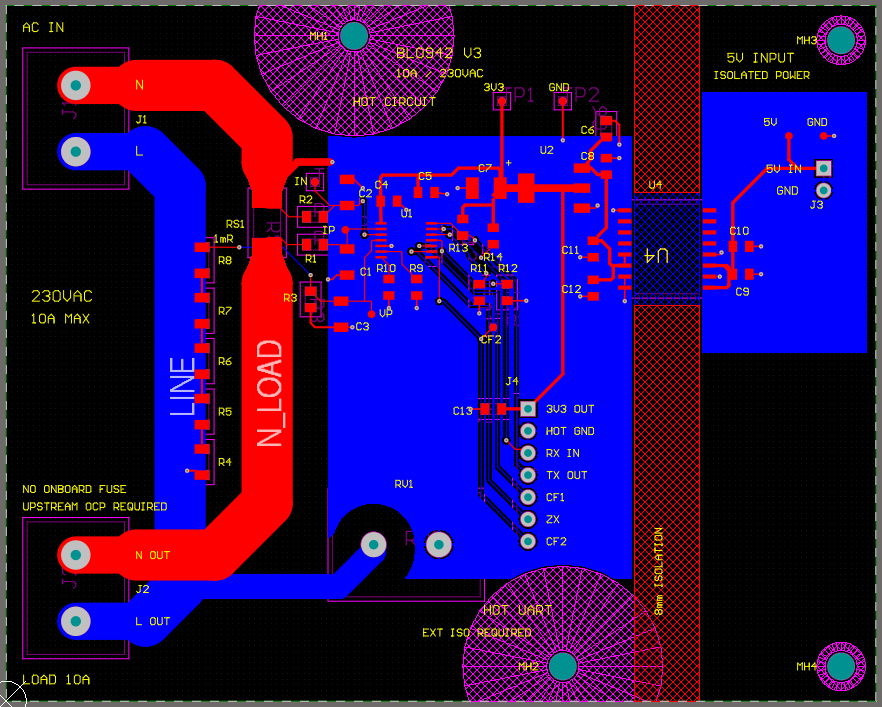
Figure: Routed BL0942 layout at 100 × 80 mm with the 8 mm isolation gap.
As the final step on the same PCB, we asked the AI to compact the layout. It reduced the outline from 100 × 80 mm to 80 × 64 mm, about 36% less area.
It moved the five divider resistors into a horizontal row, rotated the UART header J4 to a horizontal orientation, and relocated the mounting holes. Connectivity did not change, and the 8 mm HOT_COLD clearance rule was not relaxed.
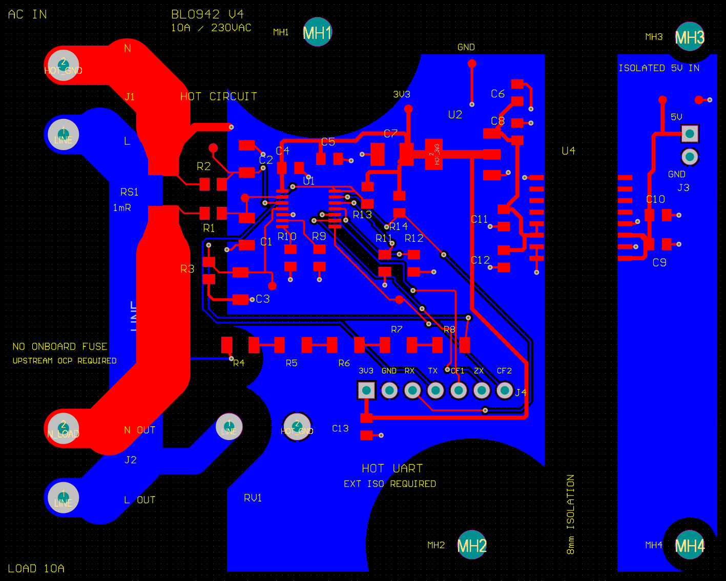
Figure: Final BL0942 layout after compaction to 80 × 64 mm through Altium MCP.
Step 5: Verification and the Fabrication Files Altium MCP Produced
Through Altium MCP, the AI checked the final board against the rules with native DRC and against the schematic pin by pin, then checked the exported files against the live PCB.
Checks on the Final Board
| Check on the 80 × 64 mm Board | Result |
|---|---|
| Multi-pad nets fully routed | 23 of 23 |
| Native Altium DRC violations | 0 |
| Schematic pins vs. component copper pads | 112 vs. 113, 0 mismatches |
| ERC result | 0 errors, 8 warnings kept visible |
| Return-via proximity advisories | 20, documented rather than cleared |
| Drill hits matched to the live PCB | 61 plated and 4 non-plated, 0 mismatches |
| Gerber outline | Closed rectangle, 80.00009 × 64.00013 mm |
- 113 pads for 112 pins: the AMS1117 tab is a second copper pad on its output pin.
- 8 ERC warnings: nets with no driving source, such as the passive sensing inputs. They were kept, not suppressed.
On the 100 × 80 mm layout, the last DRC run before sign-off reported 27 net antennae and 5 silkscreen-to-solder-mask clearance violations. The AI cleared them, and the board passed with zero violations before and after compaction.
Fabrication Files and Documents Created
| File | What It Is For |
|---|---|
| Gerber layers: GTL, GBL, GTS, GBS, GTO, GTP | Copper and solder mask on both sides, plus top silkscreen and top paste |
| Board outline: GKO, from Mechanical 3 | The 80 × 64 mm profile |
| Plated and non-plated Excellon drill files | 61 plated holes and 4 mounting holes, in separate files |
| Fabrication notes | 2 layers, 70 µm copper per side, about 1.6 mm, four 3.2 mm NPTH holes, main warnings |
| BOM and placement CSV files | 36 physical parts with MPN, LCSC number where available, datasheet link, and position |
| OutJob, DRC, and footprint-comparison reports | Regenerating the outputs and recording the checks |
| Per-pin connection CSV | Every pad compared with its schematic net |
The package also holds the native Altium project and libraries. Confirm the placement file's rotation conventions with your assembler. Before you order, run a design rule check against your fabricator's limits, generate Gerber files in Altium Designer, and compare your rules with the JLCPCB PCB capabilities.
Altium MCP Accuracy: Where the Engineer Still Had to Step In
In our experience, AI through Altium MCP can shorten the time to a prototype, but it cannot yet design a full PCB without human input. GPT-6 misread the intent at several points, and each needed correction.
Where the AI saved time:
- Drafting speed: it created files, schematics, footprints, and symbols much faster than manual CAD work.
- Component search: it can help identify parts that a plain search-engine query may miss, compare them, and suggest a suitable alternative.
- Repeatable checks: DRC, ERC, and pin-to-pad results came back as data that could be checked again.
Where the engineer stepped in:
- Components: the AI needed the reference circuit before it included the shunt and the mains divider.
- Schematic: it added an onboard fuse and a signal isolator, which we chose to handle off-board.
- Placement: its first placement ignored the current path until we gave it a reference.
- Routing: the autorouter stopped at 57.8%, so the remaining routes needed explicit, reviewed geometry.
At least 1,300 MCP tool calls were logged across the project, counted from the saved job files. Treat each AI output as a draft to review.
GPT-6 vs. Claude for Altium MCP: Why Computer Use Mattered
The main difference we observed was computer use. Codex gives GPT-6 a computer-use skill so the model can interact with the live Altium window. In our run, it used this once, while revising the main schematic: its screenshot tool had been capturing a minimized window instead of the schematic, so it checked the live Altium window directly.
We covered the same Altium MCP workflow with Claude Code in a companion article. In our Claude Code setup, no computer-use tool was connected, so visual checks relied on exported renders and the engineer's review. For an open-source EDA flow, see our guide to KiCad MCP with Claude Code.
Conclusion
Altium MCP can help you design a PCB with GPT-6 in Altium, but not without an engineer: the AI chose the parts, drew the schematic, and placed, routed, and checked the board, while the engineer supplied references and corrected each stage.
The key is to give AI the right inputs: datasheets, reference circuits, and clear design requirements. Review the MCP server before granting write access, check each stage, and never assume a routed board is ready for manufacturing. The real test comes when your PCB becomes a physical board.
FAQs About Altium MCP
Is Altium MCP Safe to Use on a Real Project?
Only with precautions. These servers are third-party code, and most can write to a live design, so back up the project, review the repository and its data handling, and start eda-agent with EDA_AGENT_READONLY=1.
Can AI Design a Complete PCB in Altium Designer?
Not without an engineer. In our test, GPT-6 chose the parts, drew the schematic, and placed, routed, and checked the board, but it needed a reference circuit, a placement reference, and corrections at each stage.
Does Altium MCP Work with Codex and Claude?
Yes. eda-agent speaks standard MCP over stdio, and its README gives Claude Code setup steps. In our setup, Codex could also check the live Altium window through computer use.
Does Altium MCP Control the Mouse and Keyboard?
Usually not. eda-agent works through Altium's scripting bridge, but it can fall back to UI automation for dialogs with no API. EDA_AGENT_UI_AUTOMATION=0 turns it off.
Which Altium Designer Versions Work with Altium MCP?
Recent versions on Windows, with AD20 or later preferred by the eda-agent README. Our test ran eda-agent 0.8.1 on Altium Designer 26.11.1.5.
Popular Articles
• AI Tools for PCB Design: Which Tool Fits Your Workflow Stage?
• AI PCB Design: From Prompt to PCB with EasyEDA Pro
• GPT-6 Astra PCB Design in KiCad: From Brief to Verified Native Project
• GPT-6 Astra PCB Design in EasyEDA Pro: What Worked, What Failed, and What We Learned
• How to Design Your Own Keyboard PCB: From Layout to Firmware
Keep Learning
KiCad MCP: How to Design a PCB with Claude Code [Step-by-Step]
Key Takeaways Claude can design PCBs in KiCad: By connecting Claude to KiCad through an MCP server, you can use AI to create and modify PCB designs. In this project, Claude helped turn a 5 A XL4015 buck converter netlist into a two-layer, 63 × 33 mm PCB layout with zero ERC violations and zero DRC errors after minor initial fixes. Set up Claude securely: Use a KiCad MCP server that starts in read-only mode. Review the server code before installing it, connect through stdio, and allow editing only in a......
Altium MCP: AI PCB Design with GPT-6 and Codex [Step-by-Step Guide]
Altium MCP connects Altium Designer to an AI assistant through a Model Context Protocol (MCP) server, so the AI calls Altium's own scripting functions instead of clicking through screenshots. We tested it with GPT-6 in Codex and the open-source eda-agent server on a 230 VAC, 10 A BL0942 energy-metering board, from datasheet to DRC-clean fabrication files. The AI chose the parts, drew the schematic, and placed, routed, and checked the board. The circuit decisions, the placement reference, and the corre......
AI Tools for PCB Design: Which Tool Fits Your Workflow Stage?
Note This article is intended to provide an independent technical overview of AI-powered PCB design tools based on publicly available product information. Product features and capabilities may change over time. AI tools can now assist with PCB architecture, schematic generation, component selection, placement, routing, and design verification. However, different tools target different stages of the PCB workflow. This guide compares AI tools for PCB design based on what they actually do, what inputs th......
From Concept to Production: PCB DFM Guidelines and Analysis
Key Takeaways PCB DFM (Design for Manufacturing) is the bridge between design intent and manufacturing reality, ensuring a board can actually be fabricated and assembled with high yield. Essential DFM guidelines cover trace width and spacing, annular rings, via placement and drill sizes, soldermask and silkscreen, surface finish, and panelization. Modern DFM analysis is data-driven and automated, and many manufacturers now offer free DFM tools that check Gerber and drill files against fabrication and ......
Understanding PCB Resistance: Key Factors, Testing Methods, and Design Best Practices
How easily current flows through a circuit board is determined by its resistance. Although some resistance is provided by each trace and component on the board, the objective is to reduce it. When the material that electrons pass through blocks or slows down their flow, resistance results. Energy is lost as a result of this obstruction, frequently as heat. Trace resistance is a crucial factor in determining the circuit's operational current in power-related circuits, such as amplifier units. To guaran......
PCB Routers: Essential Tools for Modern Circuit Design
Introduction In modern PCB production, routing machines (commonly called PCB routers or CNC routers) play a critical role. They are used to cut the board outline, create V-grooves for depanelization, mill slots, and finish edges with high precision. As electronic devices become smaller and more complex, PCB routers ensure clean, accurate, and repeatable results. This article explains what PCB routers are, their types, key applications, best practices, and how JLCPCB integrates advanced routing in its ......