A Beginner's Guide to Basic Electronic Components: Functions, Symbols & Uses
11 min
- Basic Electronic Components List: Quick Comparison
- Understanding Electronic Component Categories
- Top 10 Basic Electronic Components and Their Functions
- Common Electronic Component Symbols
- Common Electronic Components on a PCB
- How to Choose the Right Electronic Components
- Conclusion
- FAQs about Electronic Components

Every circuit, from a simple LED flashlight to a microcontroller board, is built from the same handful of common electronic components. This guide breaks down the ten basic electronic components you will encounter most often:
- What each component does
- How it works
- Key specifications
- Where engineers use it
By the end, you will be able to recognize these electronic circuit components on a schematic, a PCB, or a parts bin, and know exactly why each one is there. These electronic components are the building blocks of nearly every PCB and electronic circuit.
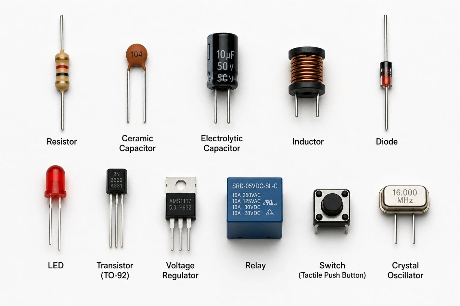
Figure: Basic electronic components including resistors, capacitors, diodes, transistors, relays, and crystal oscillators.

- JLCPCB Parts Library is designed specifically for PCB assembly. It provides access to 700,000+ electronic components from authorized distributors, allowing users to pre-select verified parts ready for manufacturing.
- By combining component sourcing with PCB assembly, this helps streamline BOM preparation, reduce sourcing risks, and ensure a smoother transition from circuit design to finished assembled boards.
Basic Electronic Components List: Quick Comparison
Here is a quick reference electronic components list showing what each part does and which category it belongs to.
| Component | Primary Function | Category |
|---|---|---|
| Resistor | Limits current | Passive |
| Capacitor | Stores electrical charge | Passive |
| Inductor | Stores magnetic energy | Passive |
| Diode | Allows one-way current flow | Active |
| LED | Emits light | Active |
| Transistor | Amplifies or switches signals | Active |
| Voltage Regulator | Maintains stable voltage | Power |
| Relay | Electrically controlled switch | Electromechanical |
| Switch | Opens or closes a circuit | Electromechanical |
| Crystal Oscillator | Generates clock signals | Timing |
Understanding Electronic Component Categories
These common electronic components are essential to modern design and are generally categorized as basic electronic components, including passive, active, electromechanical, and timing devices.
Passive components store or control energy, active components regulate signal flow, electromechanical components physically switch circuits, and timing components generate clock signals.
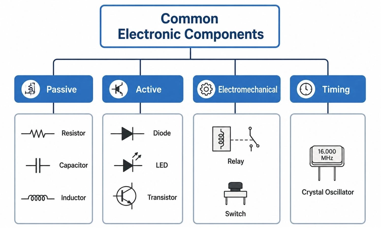
Figure: Common electronic components chart classifying passive, active, electromechanical, and timing devices with circuit symbols.
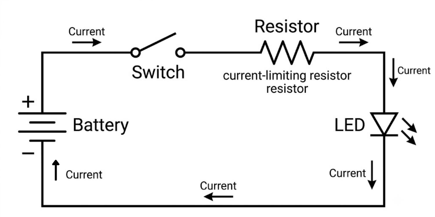
Figure: Basic electronic circuit demonstrating how multiple electronic components work together.
Top 10 Basic Electronic Components and Their Functions
1. Resistor
A resistor opposes the flow of current in a circuit. This behavior follows Ohm's Law (V = IR), which relates voltage, current, and resistance.
Why It Matters: Without resistors, LEDs would burn out instantly and logic signals would become unstable.
Typical Resistor Values: 220 ohms, 1 kohm, 10 kohms
Key Specifications
- Resistance (ohms)
- Tolerance
- Power rating
Common Applications
- Current limiting for LEDs
- Pull-up and pull-down resistors
- Feedback networks in amplifiers
Learn More: For assistance with identifying the markings on surface-mount variations, refer to this detailed SMD resistor code guide.
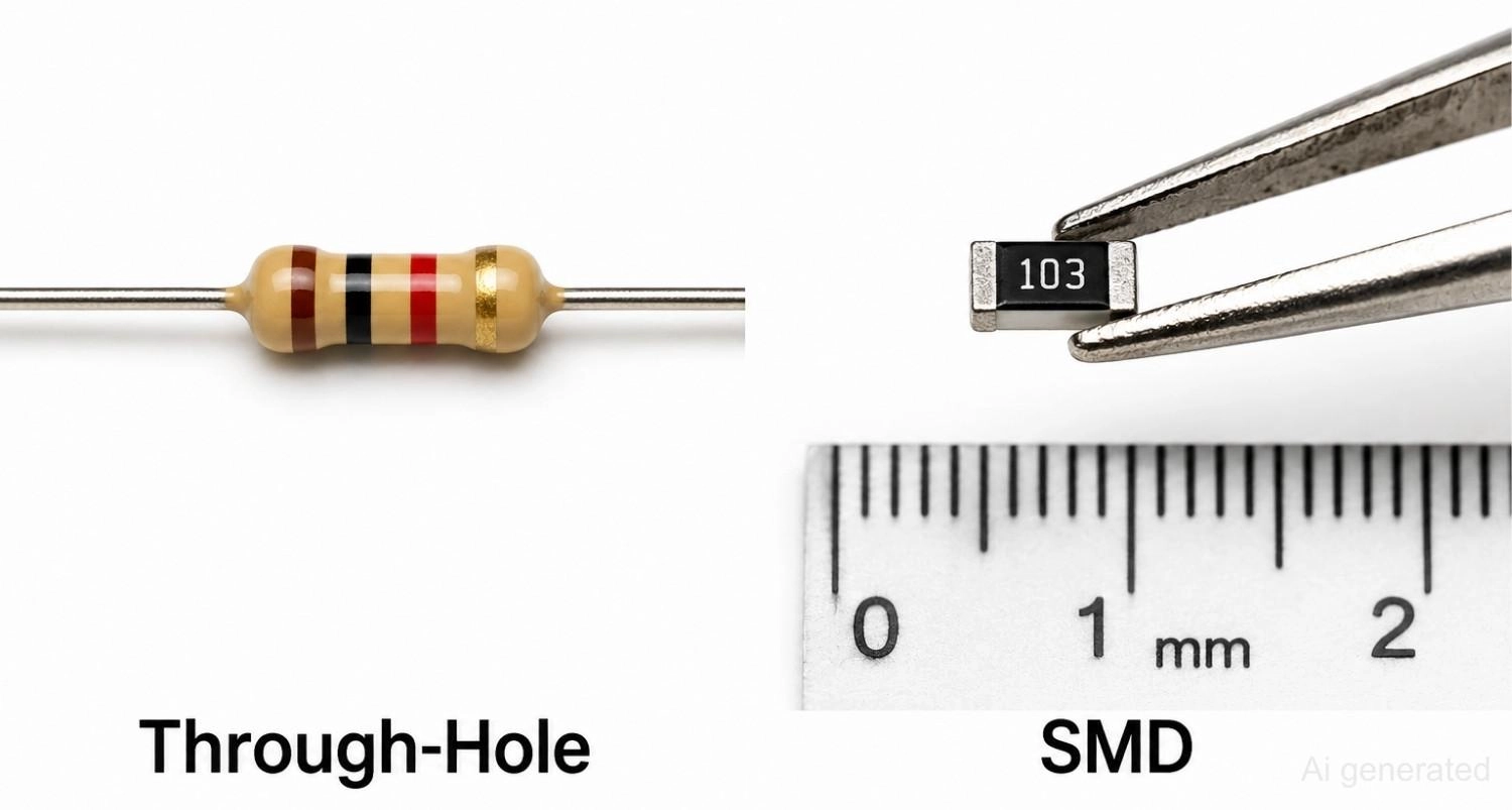
Figure: Comparison of through-hole and SMD resistor types.
2. Capacitor
A capacitor stores electrical charge in an electric field between two conductive plates. As the voltage changes, a capacitor charges or discharges, making it useful for smoothing and filtering signals.
Why It Matters: Without capacitors, power supplies would be noisy and digital circuits would suffer from voltage glitches.
Typical Capacitor Values: 100 nF, 10 uF, 100 uF
Key Specifications
- Capacitance
- Voltage rating
- Equivalent series resistance (ESR)
Common Applications
- Power supply filtering
- Noise suppression and decoupling
- Timing circuits
Learn More: Ensuring proper orientation is crucial during assembly; you can study how to orient these polarized devices in our comprehensive capacitor polarity guide.
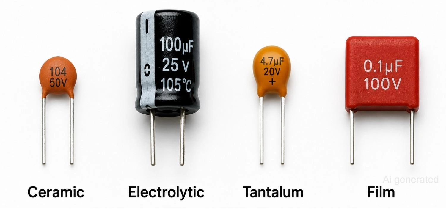
Figure: Comparison of ceramic, electrolytic, tantalum, and film capacitor types.
3. Inductor
An inductor stores energy in a magnetic field when current passes through its coiled wire. Inductors resist sudden changes in current, which makes them valuable for filtering and energy conversion.
Why It Matters: Without inductors, switching power supplies couldn't smooth their output current efficiently.
Key Specifications
- Inductance
- Saturation current
- DC resistance (DCR)
Common Applications
- Buck converters
- EMI filters
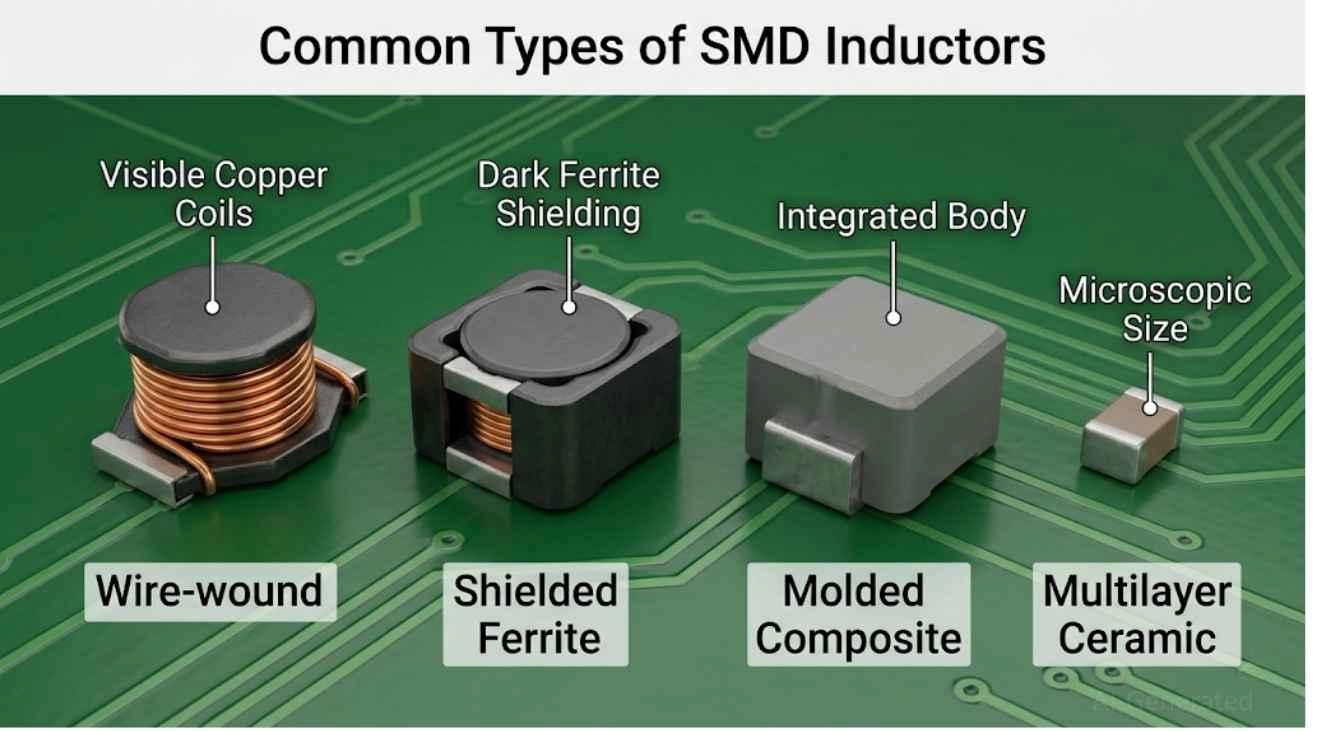
Figure: Common SMD Inductor Types
4. Diode
A diode allows current to flow in only one direction. When forward-biased, current passes through with minimal resistance; when reverse-biased, the diode blocks current flow almost entirely.
Why It Matters: Without diodes, reverse power connections could destroy an entire circuit board instantly.
Key Specifications
- Forward voltage
- Reverse voltage
- Current rating
Common Applications
- Rectifier circuits
- Reverse polarity protection
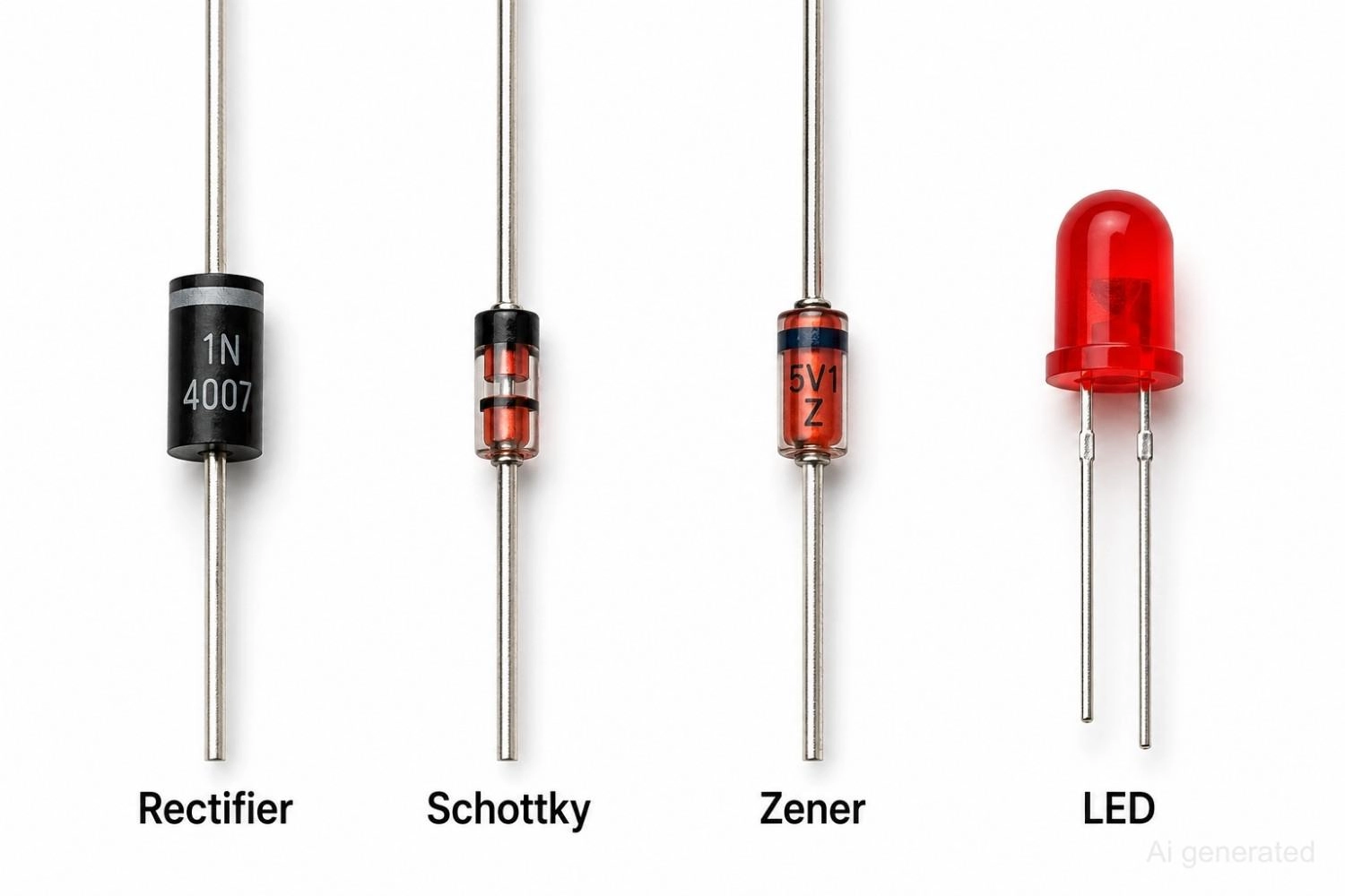
Figure: Comparison of rectifier, Schottky, Zener, and LED diode types.
5. Light Emitting Diode (LED)
An LED produces light when current flows through it in the forward direction. Because LEDs are current-sensitive, they almost always require a series resistor to limit current and prevent damage.
Why It Matters: Without a current-limiting resistor, an LED can burn out within seconds of power-up.
Key Specifications
- Forward voltage
- Forward current
- Brightness (luminous intensity)
Common Applications
- Status indicators
- Digital displays
- General lighting
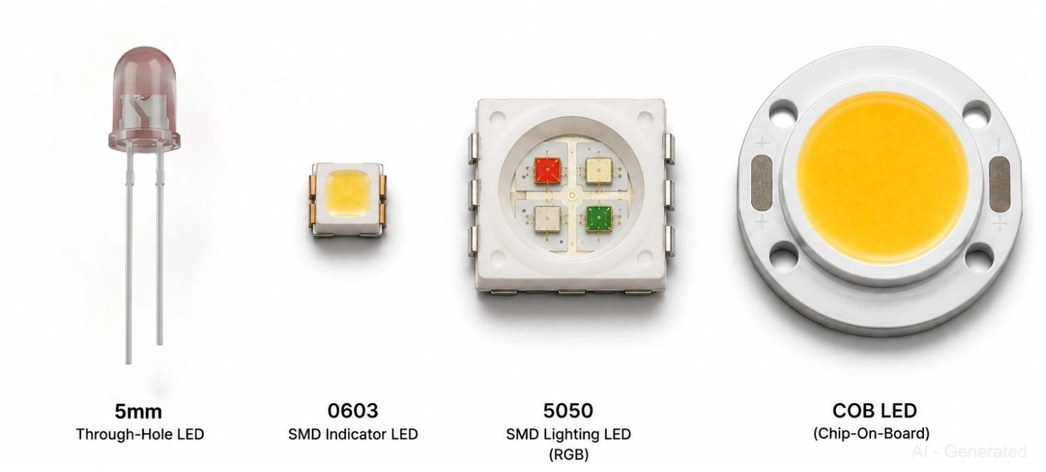
Figure: Comparison of LED types
6. Transistor
A transistor can act as an electronic switch or as a signal amplifier. The two most common types are the bipolar junction transistor (BJT) and the metal-oxide-semiconductor field-effect transistor (MOSFET).
Why It Matters: Without transistors, microcontrollers couldn't switch motors, relays, or high-current loads on and off.
Key Specifications
- Current rating
- Voltage rating
- Gain (hFE for BJTs)
Common Applications
- Motor drivers
- Digital logic circuits
Learn More: For a deeper dive into choosing between these active components, check out our comparative analysis on BJT vs MOSFET.
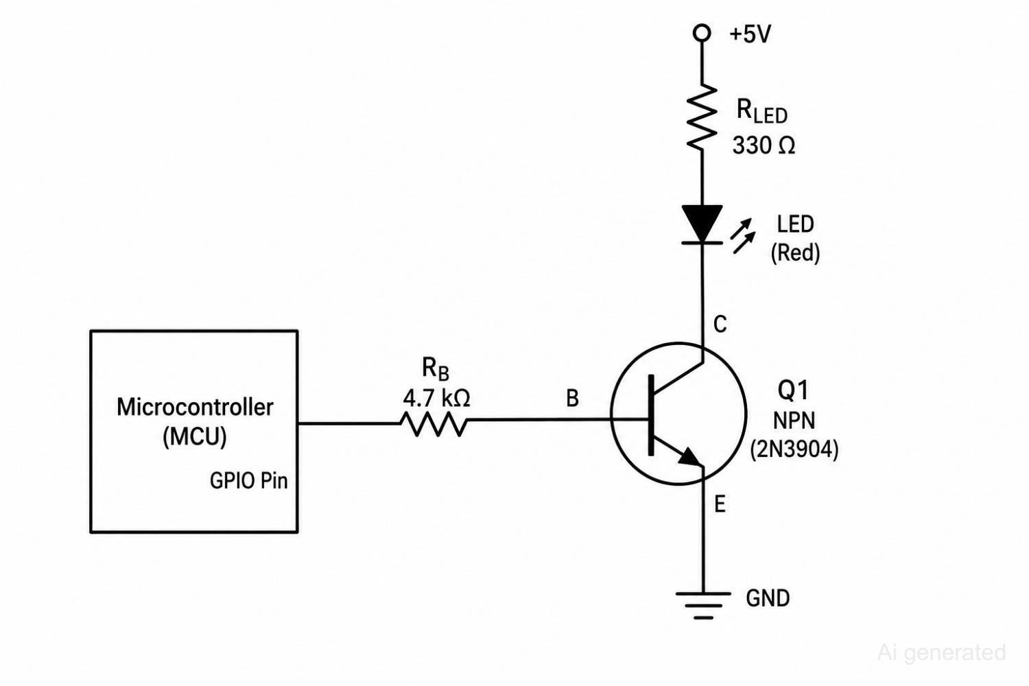
Figure: NPN transistor switching circuit controlled by a microcontroller.
7. Voltage Regulator
A voltage regulator maintains a stable output voltage regardless of fluctuations in input voltage or load current, protecting sensitive downstream electronics from damage.
Why It Matters: Without regulation, a noisy or fluctuating supply rail can corrupt sensor readings and crash microcontrollers.
Voltage Regulator Types
- Linear regulators
- Switching regulators
Linear regulators are simple and low-noise but dissipate excess voltage as heat, while switching regulators achieve much higher efficiency by rapidly switching energy through inductors and capacitors.
Common Applications
- MCU power supplies
- Embedded systems
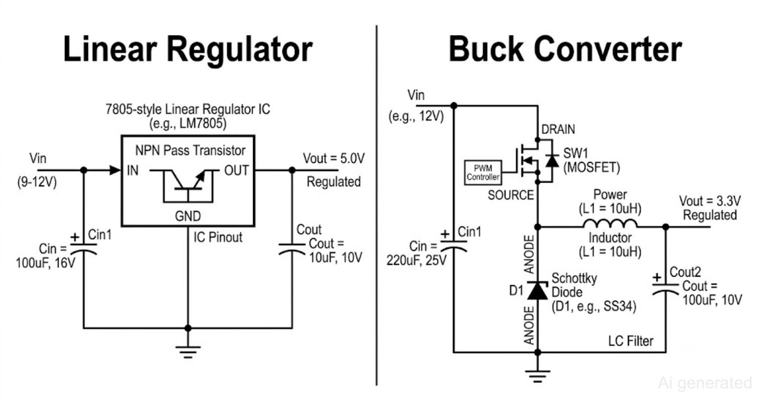
Figure: Comparison of linear regulator and buck converter voltage regulation methods.
8. Relay
A relay acts as an electrically controlled switch, using a small control signal to open or close a separate, often higher-power, circuit. Relays also provide galvanic isolation between control and load circuits.
Why It Matters: Without relays, a low-power microcontroller couldn't safely switch high-voltage household appliances.
Relay Types
- SPST (single-pole, single-throw)
- SPDT (single-pole, double-throw)
- Solid-state relay
Common Applications
- Home automation systems
- Industrial control panels
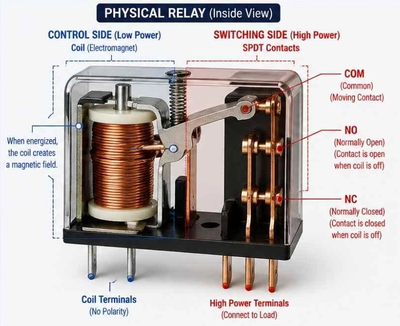
Figure: Internal diagram of a relay showing the coil, contacts, and load.
9. Switch
An electronic switch gives users direct control over a circuit, letting them manually open or close a connection.
Why It Matters: Without switches, there would be no simple way for a user to turn a device on or off.
Switch Types
- Push button
- Toggle
- Slide
- DIP switch
Common Applications
- Power on/off control
- Configuration settings
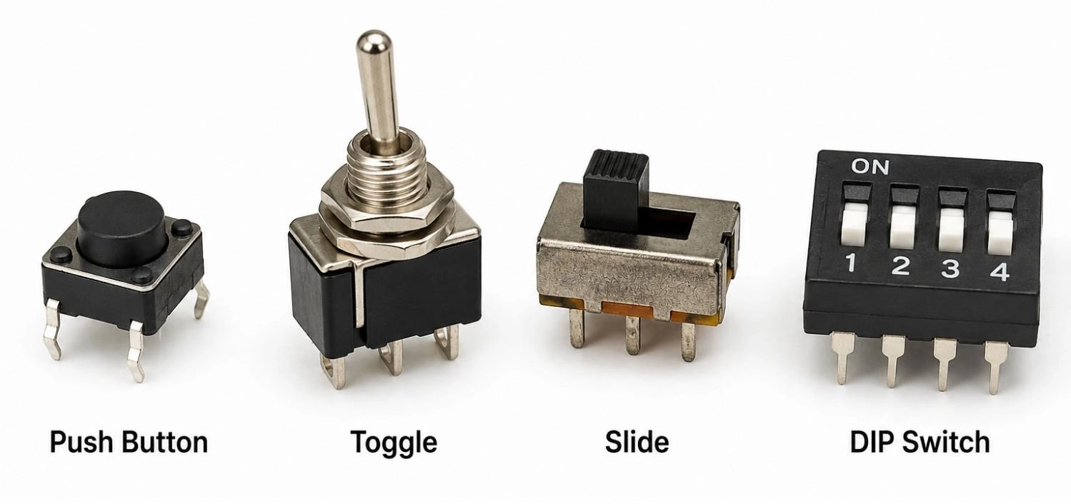
Figure: Different types of switches: push button, toggle, slide, and DIP switch.
10. Crystal Oscillator
A crystal oscillator generates a precise, stable clock signal using the piezoelectric effect, where mechanical vibration in a quartz crystal produces a consistent electrical frequency.
Why It Matters: Without a stable clock source, a microcontroller's timing, communication, and data processing would all drift out of sync.
Typical Crystal Oscillator Frequencies: 8 MHz, 16 MHz, 25 MHz, 32.768 kHz
Key Specifications
- Frequency
- Tolerance
- Stability
Common Applications
- Microcontroller clock sources
- Communication systems
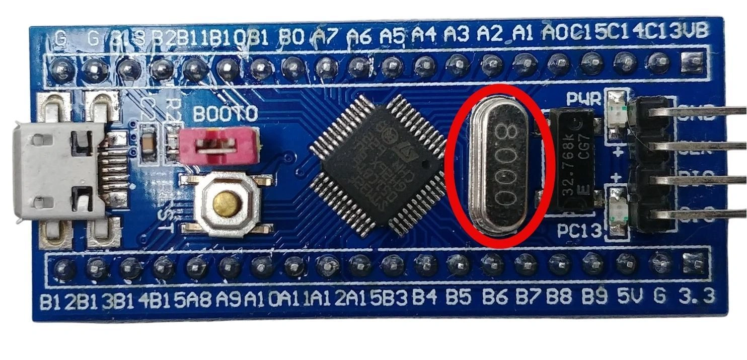
Figure: Crystal oscillator circled on an STM32 board
Common Electronic Component Symbols
Every schematic replaces physical parts with standardized symbols, so reading a circuit diagram fluently means recognizing these shapes on sight. The chart below covers the symbols you will run into most often, from basic passives through transistor polarity and common reference markers.
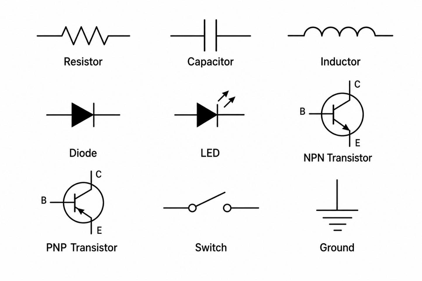
Figure: Common electronic component symbols chart showing resistor, capacitor, inductor, diode, LED, NPN transistor, PNP transistor, switch, and ground symbols.
Common Electronic Components on a PCB
Once you start reading a real schematic or bare board, PCB components are usually identified by reference designators rather than full names. Recognizing these designators makes it much easier to navigate a PCB layout or bill of materials.
For example, if a schematic references R5 or C12, the prefix immediately identifies the component type before you even inspect its value.
| Reference | Component |
|---|---|
| R | Resistor |
| C | Capacitor |
| L | Inductor |
| D | Diode |
| LED | LED |
| Q | Transistor |
| U | IC/Regulator |
| K | Relay |
| SW | Switch |
| Y | Crystal Oscillator |
Table: Table of standard PCB reference designators (R, C, L, D, LED, Q, U, K, SW, Y) and the component each one identifies.
On a populated board, resistors and capacitors cluster near ICs for decoupling, transistors sit near power stages, and crystal oscillators sit close to the microcontroller's clock pins to minimize noise.
During layout, place decoupling capacitors close to IC power pins and keep crystal oscillators near the clock inputs to maintain signal integrity.
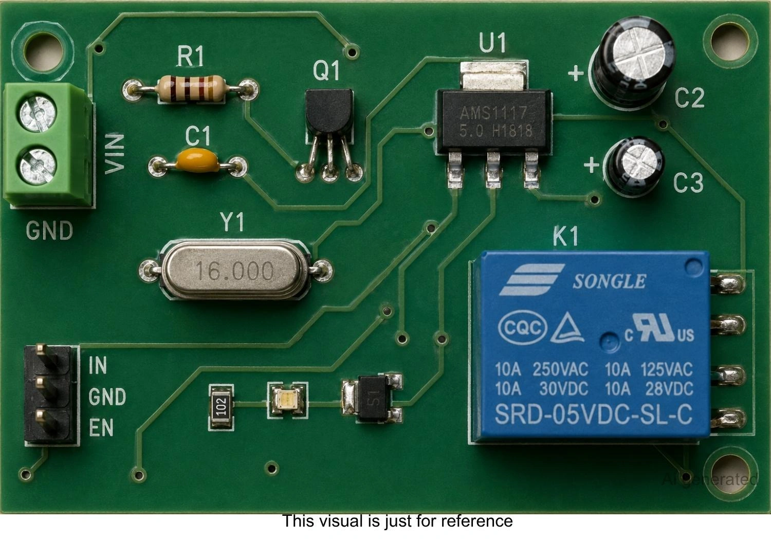
Figure: PCB with labeled resistors, capacitors, transistors, regulator, crystal oscillator, and relay.
How to Choose the Right Electronic Components
When selecting common electronic components, it’s vital to weigh both active and passive electronic components against your circuit's real operating conditions. Mastering the selection of these basic electronic components ensures your design remains robust.
1. Check Electrical Ratings
Always confirm a component's voltage, current, and power ratings exceed your circuit's actual operating conditions, with margin for safety.
2. Consider Package Type
Decide between through-hole and surface mount packages based on your assembly method, available board space, and mechanical requirements. For a structural comparison of these mounting techniques, read our technical breakdown of surface mount vs through-hole technologies.
3. Verify Availability
Check your Bill of Materials (BOM) against live factory inventory databases(JLCPCB Parts) to ensure all required components are in stock. This process typically involves parsing manufacturer part numbers or specific internal part codes. If a component is unavailable or out of stock, the system should allow you to search the global library for drop-in replacements or flag the item to be omitted (Do Not Place) to avoid production delays.
4. Design for PCB Assembly
Favor standard, widely supported packages to keep your design compatible with common manufacturing processes and avoid costly custom tooling.
Conclusion
Resistors, capacitors, inductors, diodes, LEDs, transistors, voltage regulators, relays, switches, and crystal oscillators are among the most common electronic components found in modern circuits. Whether you are learning about basic electronic components for the first time or optimizing a complex PCB, understanding their functions and applications provides a solid foundation for any electronics project.
FAQs about Electronic Components
Q: What is the main structural difference between active and passive electronic components?
Active components (like transistors and diodes) require external power to manipulate or amplify current. Passive components (like resistors and capacitors) function without external power and can only store, dissipate, or release electrical energy.
Q: Why do polarized capacitors and diodes have strict mounting orientation rules?
Polarized components are built to handle electrical potential in one direction. Installing them backward blocks correct operation and can lead to thermal stress, component failure, or a short circuit on the PCB.
Q: How do environmental factors like operating temperature impact component selection?
High temperatures lower the efficiency of voltage regulators, decrease capacitance, and drop resistor power ratings. This requires design safety margins, known as component derating, to maintain hardware reliability.
Q: How do SMT and through-hole components differ in high-frequency applications?
SMT components deliver superior high-frequency performance because they lack long wire leads. Through-hole leads behave as parasitic inductors and capacitors, which can distort high-speed and RF signals.
Q: What role do transient voltage suppressors play in protecting sensitive PCB components?
TVS diodes protect sensitive active devices like microcontrollers from ESD and voltage spikes. Placed close to entry ports, they safely clamp transient high voltages and divert excess current to ground.
Q: Why is component derating critical for long-term PCB reliability?
Derating means operating components safely below their maximum electrical limits (such as running a 25V capacitor on a 12V rail). This margin ensures voltage or current ripples do not stress materials over time.
Popular Articles
• PCB Silkscreen: All You Need to Know
• The Comprehensive Guide to Circuit Symbols: Key to Understanding Electrical and Electronic Diagrams
• Design Guidelines for PCB Using FR4 Substrates
• Choosing the Best PCB Color-Enhancing Aesthetics and Functionality
• PCB Board Design: A Step-by-Step Guide for Beginners
Keep Learning
ESP32 Power Consumption Explained: Current Draw, Sleep Modes, and Battery Life
Key Takeaways Power consumption by mode: The ESP32 draws around 240 mA during Wi-Fi transmission, 0.8 mA in light sleep, and just 10 µA in deep sleep, based on Espressif's typical datasheet figures. Deep sleep current: The ESP32 can draw 10 µA in deep sleep, with only the RTC timer and memory remaining powered. Keeping the ULP coprocessor running increases current consumption to around 100–150 µA. Development board power consumption: A typical ESP32 development board can draw around 6.5 mA even in dee......
ESP32 Pinout Reference: Which GPIO Pins Are Safe to Use and Avoid?
Key Takeaways GPIO count: The ESP32 chip has 34 GPIOs, and the ESP32-WROOM-32E module exposes 26 of them. General-purpose pins: Fifteen module GPIOs carry no boot, flash, or input-only restrictions: GPIO4, GPIO13, GPIO14, GPIO16 to GPIO19, GPIO21 to GPIO23, GPIO25 to GPIO27, GPIO32, and GPIO33. Strapping pins: GPIO0, GPIO2, GPIO5, GPIO12, and GPIO15 are sampled at reset, so any circuit connected to them must maintain the level required by the boot mode. Input-only pins: GPIO34, GPIO35, GPIO36, and GPI......
PCB Silkscreen: All You Need to Know
Key Takeaways The PCB Silkscreen Guide demonstrates that a properly designed legend layer is essential to prevent assembly failures and ensure long-term hardware reliability. By mastering modern manufacturing methodologies like Direct Legend Printing (DLP) and aligning layouts with JLCPCB's strict DFM design rules—including the absolute 0.8 mm character height limit and the automated 0.15 mm silkscreen clipping protocol driven by solder mask precedence—engineers can seamlessly eliminate cold joints an......
A Beginner's Guide to Basic Electronic Components: Functions, Symbols & Uses
Every circuit, from a simple LED flashlight to a microcontroller board, is built from the same handful of common electronic components. This guide breaks down the ten basic electronic components you will encounter most often: What each component does How it works Key specifications Where engineers use it By the end, you will be able to recognize these electronic circuit components on a schematic, a PCB, or a parts bin, and know exactly why each one is there. These electronic components are the buildin......
How to Read and Create PCB Schematics
Key Takeaways Read Schematics: Understand symbols, net labels, and component values. Design in EasyEDA: Place components and create circuit connections. Run Design Checks: Use ERC and DRC to identify potential issues. Verify Components: Check pin assignments and PCB footprints. Prepare for Manufacturing: Validate PCB layouts and manufacturing files. Printed circuit board (PCB) design begins with a clear understanding of how the electronic circuit should function. A schematic diagram represents the cir......
Maximizing Circuit Reliability with PCB Test Points and Smart DFT
Key Takeaways Early Fault Catching: Test points drastically reduce diagnosis time and prevent costly field failures. Standard Pad Sizing: Use 1.0 mm flat copper pads with 2.54 mm spacing for optimal fixture contact. Protect High-Speed Signals: Keep branch traces short to prevent capacitive loading and resonance. Single-Sided Access: Place all test pads on the bottom layer to cut fixture costs. Right Test for Volume: Use flying probe for prototypes and bed-of-nails ICT for mass production. A PCB test p......