
How to Create a Bluetooth-Controlled Car With Arduino: A Step-by-Step Guide
11 min
- Step 1: Define the Mechanical and Electrical System of the Arduino Bluetooth Car
- Step 2: Select Components for the Arduino Nano RC Car PCBA
- Step 3: Design the Schematic for an Arduino Nano Bluetooth RC Car
- Step 4: Design the PCB Layout for a Two-Wheel Robot Car PCBA
- Step 5: Manufacture the Arduino Nano Bluetooth RC Car Using PCBA Services
- Step 6: Program the Arduino Nano for Bluetooth Car Control
- Step 7: Control the Arduino Bluetooth RC Car with a Mobile Phone
- Step 8: Test and Optimize the Arduino Bluetooth Controlled Car
- FAQ about Arduino Bluetooth Controlled Car
- Conclusion: Arduino Bluetooth Controlled Car
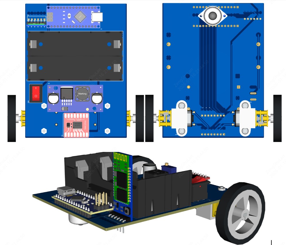
This tutorial walks through the complete engineering and implementation of a two-wheel Bluetooth RC car with an Arduino Nano module on a specially designed PCBA (Printed Circuit Board Assembly).
While many hobbyists start by wiring motors and Bluetooth modules with jumper cables on a breadboard, this approach is prone to disconnection and signal noise. This guide upgrades that process by teaching you how to design a professional mainboard.
Key Design Features
- Controller: Arduino Nano used as a plug-in module.
- Drive System: Two N20 DC Gear Motors configured for differential drive.
- Driver: Surface-mount TB6612FNG MOSFET-based driver.
- Manufacturing: Professionally assembled PCB assembly service (JLCPCB PCBA) for reliability.
Step 1: Define the Mechanical and Electrical System of the Arduino Bluetooth Car
Choose a Differential Drive System
This robot does not rely on Ackerman steering (like in real cars), but rather employs a Differential Drive system.
Mechanism: The configuration comprises two powerful N20 DC motors that can operate independently and are located on opposite sides of the chassis.
Steering Logic:
- Forward: Both motors rotate at equal speed (VL = VR).
- Turn: One motor spins slower than the other (VL ≠ VR).
- Left: VL > VR
- Right: VL < VR
- Zero-Radius Turn: Motors spin in opposite directions.
Stability: A front passive ball caster is used as a third point of contact, reducing friction and allowing omnidirectional movement.
Plan the Electrical Architecture
The central processing unit in this project is the Arduino Nano. It controls the three most important subsystems:
- Communication: Deals with data transmission through the UART coming from the HC-05 Bluetooth module.
- Motor Control: It produces PWM signals for the motor driver.
- Power Distribution: Regulates battery voltage for logic and motor drive.
Crucially, the Motor Driver IC isolates the sensitive logic pins of the Arduino Nano from the high inductive voltage spikes generated by the N20 motors.
If the battery voltage is lower than the motor's rated voltage, a boost converter (such as XL6009) is used to supply the full voltage to the motors through the motor driver, thereby increasing the battery voltage.
| Subsystem | Component | Purpose |
|---|---|---|
| Controller | Arduino Nano | Motor & Bluetooth control logic |
| Motors | N20 DC motors (x2) | Differential drive actuation |
| Boost Module | XL6009 | Voltage booster from battery |
| Communication | HC-05 | Bluetooth UART Interface |
| Support | Ball caster | Front mechanical stability |
System overview table for Arduino Nano Bluetooth RC car with N20 motors
Step 2: Select Components for the Arduino Nano RC Car PCBA
The selection of correct components is necessary to build a robot PCB Assembly.
| Component | Qty | Notes |
|---|---|---|
| Arduino Nano | 1 | Plug-in module (Header Mount) |
| N20 DC Motor | 2 | Differential drive (6V-12V) |
| TB6612FNG | 1 | Dual H-bridge Driver (SMD) |
| XL6009 | 1 | Boost Converter Module |
| Rocker Switch | 1 | Kill Switch to toggle (On/Off) |
| HC-05 | 1 | Bluetooth UART Module |
| Ball caster | 1 | Front passive support |
BOM table for Arduino Nano Bluetooth RC car PCBA using N20 motors
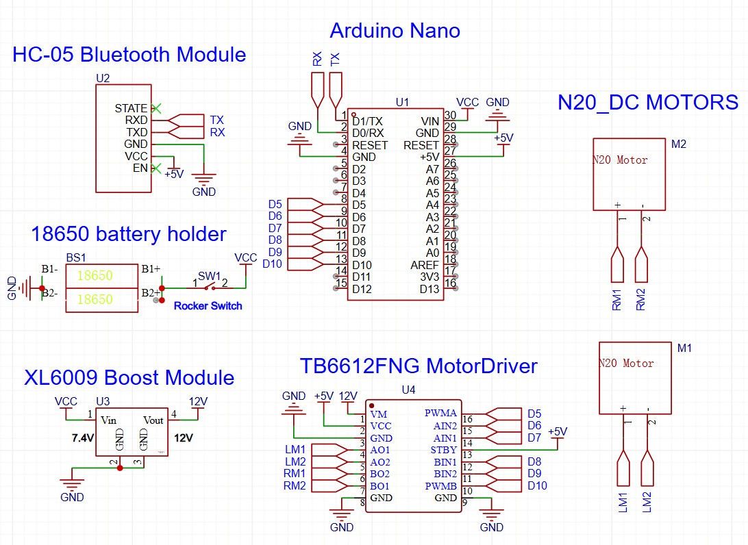
Step 3: Design the Schematic for an Arduino Nano Bluetooth RC Car
Allocate Arduino Nano Pins for Motor and Bluetooth Control
Proper pin mapping is essential for PWM generation.
| Function | Arduino Nano Pin |
|---|---|
| Motor A PWM | D5 (PWM Capable) |
| Motor A direction | D6, D7 |
| Motor B PWM | D10 (PWM Capable) |
| Motor B direction | D8, D9 |
| Bluetooth RX | D0 (RX) |
| Bluetooth TX | D1 (TX) |
Arduino Nano pin allocation for peripherals
Wire the Motor Driver for Differential Drive
- Inputs: AIN1/AIN2 connect to Nano D6/D7 to control direction (Clockwise/Counter-Clockwise) and BIN1/BIN2 connect to Nano D8/D9 to control direction (Clockwise/Counter-Clockwise).
- Speed: PWMA/PWMB connect to Nano D5/D10.
- Standby: The STBY pin on the TB6612FNG must be pulled HIGH (to VCC) or controlled by a GPIO to enable the motors.
- Outputs: AO1, AO2, and BO1, BO2 connect to the N20 Motor terminals.
Connect the Bluetooth Module for Mobile Control
Direct Connection: HC-05 TX to Arduino RX and HC-05 RX to Arduino TX.
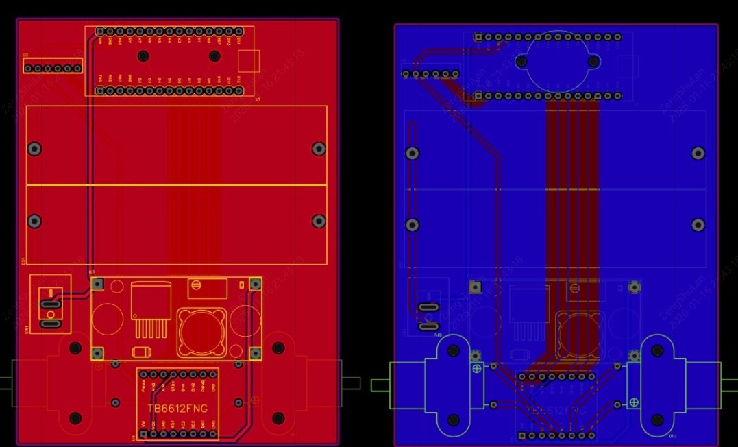
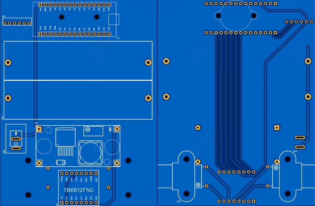
Step 4: Design the PCB Layout for a Two-Wheel Robot Car PCBA
Optimize Component Placement
- Centering: The battery holder should be positioned exactly in the middle so that the weight is evenly distributed.
- Edge Placement: Position the HC-05 module at the edge of the board. The PCB copper planes should not extend under the Bluetooth antenna area to avoid signal shielding.
- Connectors: Place JST or screw terminals for the N20 motors exactly where the motors will physically mount to keep wire runs short.
Route High-Current Motor Traces Safely on the PCB (Critical Design Tips)
Design Tips
- Trace Width: The traces carrying power to the N20 motors must be wide. Use a calculator (IPC-2221) to size them for at least 1A continuous current (typically ≥ 20 mil).
- Loop Area: Keep the Forward and Return paths for the motor current close together to minimize inductance and radiated noise.
- GND Pour: A GND pour on a PCB fills open areas with ground-connected copper, establishing a solid ground plane. It works by EMI reduction, giving low-impedance signal return paths, helping to get rid of heat, and stabilizing voltages, which is very important for signal quality and production in complicated or fast-speed designs.
Step 5: Manufacture the Arduino Nano Bluetooth RC Car Using PCBA Services
Generate Gerber, BOM, and Pick-and-Place Files for PCBA
To use the JLCPCB PCBA service, you must export three specific files from your EDA software (such as EasyEDA or KiCad):
- Gerber Files: Defines the physical copper, solder mask, and drill holes.
- BOM (Bill of Materials): A list of components containing Manufacturer Part Numbers.
- CPL (Component Placement List): The coordinates (X, Y, Rotation) for the SMT Pick-and-Place machine.
Order PCB and PCBA for the Arduino Bluetooth Controlled Car on JLCPCB
After finishing your design, you can order your assembled board by performing the following steps:
- Upload Gerbers: Go to the JLCPCB site and upload the zip file containing your Gerbers. The viewer will show your board design.
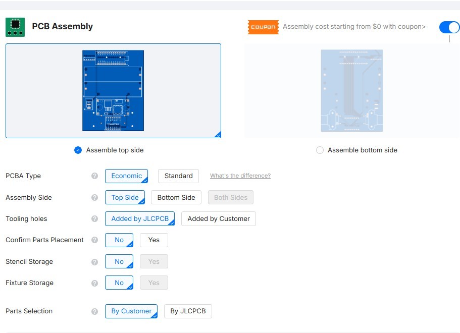
- Select PCBA: Toggle the "PCB Assembly" option to ON.

- Choose Settings: Choose "Assemble top side" (because our SMT components are on top) and then decide on "Economic" or "Standard" assembly according to your complexity.
- Upload BOM & CPL: Upload the specific files generated in the previous step.
- Part Selection: Your BOM items will be compared with the JLCPCB Parts Library through the system. Verify the parts and look at the 3D preview to confirm the correct orientation.
- Order: Proceed to checkout. JLCPCB engineers will conduct a DFM (Design for Manufacturability) review before production commencement.
Why PCBA Makes an Arduino Bluetooth Controlled Car More Reliable
- Noise Immunity: A solid PCB ground plane drastically reduces electromagnetic interference compared to jumper wires, which act as antennas.
- Vibration Resistance: N20 motors create vibration. Solder joints on a PCB are far more durable than breadboard connections.
| Metric | Breadboard | PCBA |
|---|---|---|
| Noise Immunity | Poor | High |
| Durability | Low (wires loose easily) | High (Soldered) |
| Repeatability | Low | Excellent |
Comparison of breadboard wiring vs PCBA for Arduino Nano robot car
Step 6: Program the Arduino Nano for Bluetooth Car Control
Structure the Arduino Firmware for RC Car Control
The code is to receive the characters from the serial port and transform them to motor differential speeds.
#include <SoftwareSerial.h>

// Motor Pins
const int enA = 5;
const int inA1 = 6;
const int inA2 = 7;
const int enB = 10;
const int inB1 = 8;
const int inB2 = 9;
// ... define other pins

void setup() {
  Serial.begin(9600); // Bluetooth baud rate
  pinMode(enA, OUTPUT);
  pinMode(inA1, OUTPUT);
  pinMode(inA2, OUTPUT);
  pinMode(enB, OUTPUT);
  pinMode(inB1, OUTPUT);
  pinMode(inB2, OUTPUT);
}

void loop(){
  //your logic here
}
Implement Differential Drive Logic
- Turning Left: The robot turns left when the Right Motor rotates forward at speed X, while the Left Motor is either halted or rotates backward.
Code Logic:analogWrite(RightMotor, 200); analogWrite(LeftMotor, 0); - Turning Right: Left motor rotates forward at speed X, and Right motor is either halted or rotates backward.
Code Logic:analogWrite(RightMotor, 0); analogWrite(LeftMotor, 200); - Pivot (Zero Radius): Code Logic: Left Motor BACKWARD, Right Motor FORWARD.
Add Safety Logic to Prevent Motor and Power Failures
Safety Tips
- Failsafe: In case of a disconnection of the Bluetooth link, the robot's action should be halted, not continue to drive.
- Ramping: Immediate jump from 0 to 255 PWM is to be avoided in order to save the plastic gears in the N20 motors.
Step 7: Control the Arduino Bluetooth RC Car with a Mobile Phone
Pair the Bluetooth Module with a Mobile Device
- Power up the PCBA. The HC-05 LED should blink rapidly (Pairing Mode).
- Open Bluetooth settings on your phone and pair with "HC-05".
- PIN: Usually 1234 or 0000.
Control the RC Car Using a Bluetooth Mobile App
Use a standard "Bluetooth Electronics" app.
- Configuration: Map the "Forward" arrow button to send the character 'F'. Map "Left" to 'L', etc.
- Data Flow: Phone App → Bluetooth → HC-05 → Arduino Nano (RX) → Firmware Logic → TB6612FNG → Motors.
Step 8: Test and Optimize the Arduino Bluetooth Controlled Car
Perform Electrical Testing on the PCBA and Motors
Important
Before plugging in the Nano:
- Power the board with the battery.
- Multimeter Check: Measure the 5V pin on the headers. It must be a steady 5V. If it's 7V+, do not plug in the Nano!
- Stall Current: Ensure the heat traces won't overheat by taking measurements of current while the wheels are held.
Validate Mechanical Performance
- Balance: Ensure the battery is centered so the robot doesn't tip.
- Caster Drag: In case of dragging of the front ball caster, either lubricate it or change the height of the N20 motor mounts.
FAQ about Arduino Bluetooth Controlled Car
Q: What if the TB6612FNG driver is out of stock in the library?
JLCPCB has a large library, but the availability of stock changes. You may use the "Pre-order" option to hold parts for you, or see if the L9110S driver that is listed as compatible will meet your voltage needs as a substitute.
Q: Do I need to order a stencil?
If you are using the PCBA service, no. JLCPCB creates its own internal stencil for applying solder paste. You only need a stencil if you plan to solder the SMT parts yourself at home.
Q: What is the difference between "Basic" and "Extended" parts at JLCPCB?
"Basic" parts are already loaded on the feeders and have no labor fee. "Extended" parts require a small labor fee to load the reels. To save money, filter for "Basic" parts when selecting resistors, capacitors, and LEDs.
Q: Can I power this PCBA with a standard 9V battery?
We strongly advise against it. Standard 9V (PP3) batteries cannot supply the high current needed for motors. Use a 2S Li-ion pack (7.4V) or 6xAA batteries for reliable performance.
Q: Why does the code upload fail when the Bluetooth module is plugged in?
The HC-05 utilizes the same hardware Serial pins (D0/D1) that connect to the USB port. During the uploading of sketches to the Arduino Nano, you will have to disconnect the Bluetooth module, or alternatively, you can add a switch to the power line of the Bluetooth module.
Conclusion: Arduino Bluetooth Controlled Car
This tutorial demonstrates how a simple two-wheel Arduino Nano Bluetooth RC car can be elevated into a reliable engineering project using PCBA.
The use of professional fabrication instead of breadboards guarantees that your robot can deliver perfect power to the N20 motors, have uninterrupted Bluetooth communication, and be mechanically strong enough to handle real-world applications.
Popular Articles
• How to Create a Bluetooth-Controlled Car With Arduino: A Step-by-Step Guide
• How to Design and Assemble a Reliable ESP32 Module PCB on a 2-Layer Board
• The Ultimate Guide to Relay Symbol: Coil, Contacts, Diagrams, and Circuit Applications
• How to Identify SMD LED Polarity: Markings, Testing, and PCB Tips
• The Ultimate Guide to PCBA: Process,Types and Techniques for the Electronics Enthusiast
Keep Learning
How to Design an ESP32-S3 Development Board from Scratch: A 4-Layer PCB Design Tutorial
Designing your own ESP32-S3 development board gives you complete control over your hardware architecture while preparing your IoT projects for commercial production. Instead of relying on bulkier, off-the-shelf boards, building a custom design allows you to optimize the board space, expose only the required GPIO pins, and integrate peripherals directly onto a single substrate. In this tutorial, we will design a 4-layer ESP32-S3 development board from scratch. We will walk through the entire hardware d......
Arduino LED Driver Tutorial: Control More LEDs with 74HC595 and MAX7219
Arduino GPIO pins run out quickly in larger LED projects. By utilizing dedicated LED drivers and expansion ICs, you can drastically reduce pin usage, eliminate processor-heavy multiplexing loops, and simplify display wiring. In this guide, you will learn the operational architecture, wiring configurations, cascading techniques, and optimization strategies for the 74HC595 shift register and the MAX7219 LED driver. Why Arduino Projects Need LED Driver ICs Arduino GPIO and Current Limitations An ATmega32......
How to Create a Bluetooth-Controlled Car With Arduino: A Step-by-Step Guide
This tutorial walks through the complete engineering and implementation of a two-wheel Bluetooth RC car with an Arduino Nano module on a specially designed PCBA (Printed Circuit Board Assembly). While many hobbyists start by wiring motors and Bluetooth modules with jumper cables on a breadboard, this approach is prone to disconnection and signal noise. This guide upgrades that process by teaching you how to design a professional mainboard. Key Design Features Controller: Arduino Nano used as a plug-in......
Fiducial Marks in PCB and SMT Assembly: A Complete Guide to Accuracy and Design Rules
Modern Printed Circuit Boards (PCBs) are complex, integrating high-density components like 0.4mm pitch Ball Grid Arrays (BGAs), 0201 passives, and fine-pitch Quad Flat No-Lead (QFN) packages. In this advanced manufacturing environment, achieving placement accuracy measured in micrometers is crucial. A significant challenge in automated manufacturing is how pick-and-place machines, which handle thousands of components per hour, precisely locate the PCB. A board on a conveyor system is never in the perf......
Alternating Current vs Direct Current (AC vs DC): What's the Difference?
Electric current flows in two primary forms: alternating current (AC) and direct current (DC). AC periodically reverses direction, while DC flows steadily in one direction. AC powers the industrial and residential electrical grids, while DC powers batteries, electric vehicles, and nearly all modern consumer electronics. Understanding the core differences between AC and DC matters when designing power supplies, selecting electronic components, or laying out printed circuit boards (PCBs). This guide com......
Arduino LED Multiplexing Tutorial: Control More LEDs with Fewer Pins
The Arduino Uno is a powerful tool for prototyping, but driving multiple LEDs directly quickly exhausts its 20 GPIO pins and its 200 mA absolute maximum package current limit. To bypass these hardware bottlenecks, engineers and hobbyists use LED multiplexing to scale display outputs efficiently without upgrading the microcontroller. In this guide, you will learn the core principles of LED matrix scanning, Charlieplexing, refresh timing, ghosting fixes, and practical Arduino code without relying on any......