ESP32 Power Consumption Explained: Current Draw, Sleep Modes, and Battery Life
13 min
- ESP32 Power Consumption by Mode
- ESP32 Power Modes Compared: What Stays Powered in Each Mode
- Which ESP32 Sleep Mode Should You Use?
- How Much Current Does ESP32 Deep Sleep Draw?
- Why Does an ESP32 Dev Board Draw Milliamps in Deep Sleep?
- How to Reduce ESP32 Power Consumption on a Custom PCB
- How to Calculate ESP32 Battery Life from Average Current
- ESP32 Low-Power Design in JLCPCB PCB Assembly
- Conclusion
- FAQs About ESP32 Power Consumption
Key Takeaways
- Power consumption by mode: The ESP32 draws around 240 mA during Wi-Fi transmission, 0.8 mA in light sleep, and just 10 µA in deep sleep, based on Espressif's typical datasheet figures.
- Deep sleep current: The ESP32 can draw 10 µA in deep sleep, with only the RTC timer and memory remaining powered. Keeping the ULP coprocessor running increases current consumption to around 100–150 µA.
- Development board power consumption: A typical ESP32 development board can draw around 6.5 mA even in deep sleep, about 650 times more than the chip itself. This is mainly because the voltage regulator, power LED, and USB-to-UART chip continue consuming power.
- Estimating battery life: Battery life depends on average current consumption, not just deep sleep current. For example, a custom ESP32 board that wakes for 3 seconds every 10 minutes and draws an average of 0.615 mA could theoretically run for about 108 days on a 1,600 mAh battery.
ESP32 power consumption ranges from around 240 mA during Wi-Fi transmission to just 10 µA in deep sleep, according to Espressif's datasheet. However, these figures apply to the ESP32 chip itself. The actual power consumption of a module or development board can be much higher.
Even when the ESP32 chip itself enters deep sleep, support components on typical development boards, such as the voltage regulator, power LED, and USB-to-UART chip, continue to draw current. As a result, a development board can consume hundreds of times more current than the ESP32 chip alone.
In this guide, you will learn:
- How much current the ESP32 draws in each power mode
- Which sleep mode to use, and how much current the ESP32 deep sleep draws
- Why a dev board draws milliamps in deep sleep, and how a custom PCB reaches microamps
- How to estimate battery life from average current
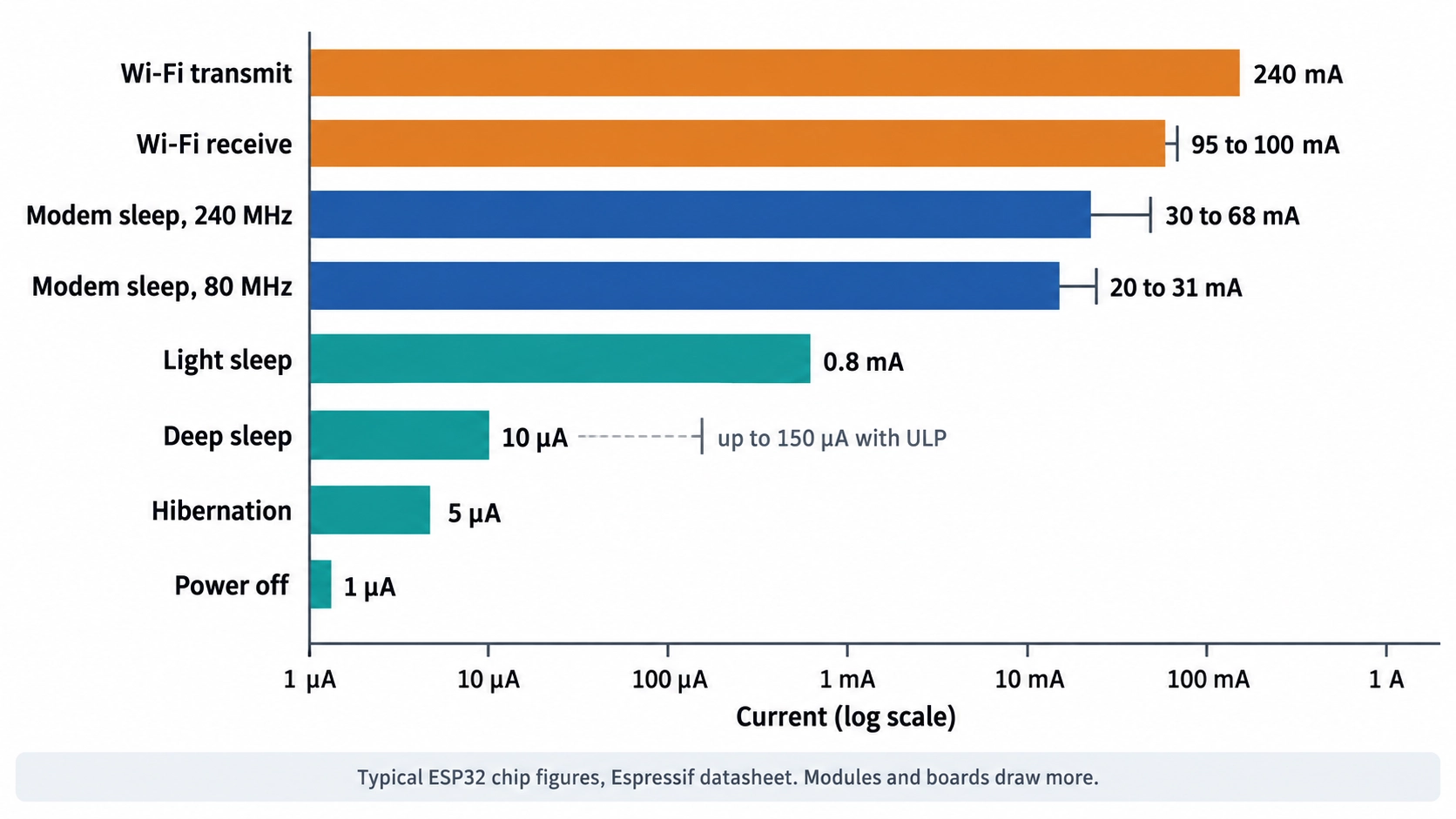
Figure: ESP32 power consumption by mode on a logarithmic scale
ESP32 Power Consumption by Mode
The ESP32 chip draws from about 240 mA down to 1 µA, depending on which of its blocks are powered. The values below are Espressif's typical figures for the original ESP32 chip, not for a module or a development board.
| Mode | Typical Chip Current | Conditions |
|---|---|---|
| Active, Wi-Fi transmit | 240 mA | 802.11b at 1 Mbps, +19.5 dBm output power |
| Active, Wi-Fi receive | 95 to 100 mA | 802.11b/g/n receive and listening |
| Active, Bluetooth transmit | 130 mA | Bluetooth or Bluetooth Low Energy (LE) at 0 dBm |
| Modem sleep | 30 to 68 mA | CPU running at 240 MHz on a dual-core chip, radio off |
| Modem sleep | 20 to 31 mA | CPU running at 80 MHz on a dual-core chip, radio off |
| Light sleep | 0.8 mA | CPU paused, RTC memory and RTC peripherals running |
| Deep sleep | 10 to 150 µA | Set by which RTC blocks stay powered |
| Hibernation | 5 µA | RTC timer only |
| Power off | 1 µA | CHIP_PU pin held low |
Note
Espressif uses 'RTC' to denote the low-power domain that remains active while the digital core sleeps, encompassing more than just a real-time clock.
ESP32 Power Modes Compared: What Stays Powered in Each Mode
The ESP32 supports five power modes: active, modem sleep, light sleep, deep sleep, and hibernation. Each mode balances power consumption, retained system state, and wake-up behavior differently.
Each deeper ESP32 power mode switches off more of the chip, reducing current and leaving more state for the firmware to rebuild after wake-up.
| Mode | CPU | Wi-Fi and Bluetooth | What Keeps Running | After the Wake-Up |
|---|---|---|---|---|
| Active | Running | On | The whole chip | Not applicable |
| Modem sleep | Running | Baseband and radio off | CPU, RAM, and digital peripherals | Continues without a restart |
| Light sleep | Paused, clock-gated | Off | RAM and CPU state, RTC memory, RTC peripherals, and the ULP coprocessor | Resumes where it stopped |
| Deep sleep | Powered off | Off | RTC controller, RTC fast and slow memory, and the ULP coprocessor | Runs the boot process again; RTC memory keeps its data |
| Hibernation | Powered off | Off | One RTC timer on the slow clock and certain RTC GPIOs | Runs the boot process again; RTC memory is powered down |
Wi-Fi and Bluetooth connections are not maintained in light sleep or deep sleep. If a device must stay connected to an access point at low power, Espressif's ESP-IDF software framework recommends enabling Wi-Fi modem sleep together with automatic light sleep.
Which ESP32 Sleep Mode Should You Use?
The decision comes down to one question: how often does the device need to run, and must it stay connected in between?
| Situation | Use |
|---|---|
| Must stay on the Wi-Fi network and respond to incoming traffic | Modem sleep with automatic light sleep |
| Runs every few seconds and must keep RAM and program state | Light sleep |
| Takes a reading every few minutes or hours, then sends it | Deep sleep with the RTC timer and RTC memory |
| Must watch a sensor while the main CPUs are off | Deep sleep with the ULP coprocessor |
| Needs only a timer or an RTC GPIO to restart, and keeps no data | Hibernation |
| Stays off until a button or supervisor enables it | Power off through CHIP_PU |
Selection Rule
For sleep durations of minutes or longer, deep sleep is most efficient. For short intervals, the energy overhead of rebooting and reconnecting to Wi-Fi can exceed deep sleep savings, making light sleep more energy-efficient overall.
How Much Current Does ESP32 Deep Sleep Draw?
ESP32 deep sleep draws 10 µA to 150 µA at the chip level, depending on which RTC blocks stay powered. The 10 µA figure applies only when the RTC timer and RTC memory are the last blocks left on.
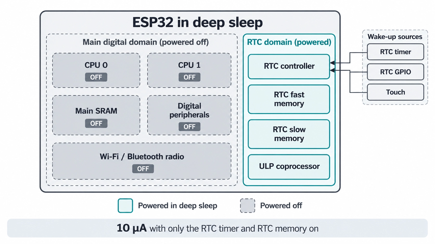
Figure: ESP32 deep sleep power
| Deep Sleep Configuration | Typical Chip Current | What Is Powered |
|---|---|---|
| RTC timer and RTC memory | 10 µA | Timer wake-up, data kept in RTC memory |
| ULP sensor-monitored pattern | 100 µA | ULP coprocessor sampling a sensor, ADC at a 1% duty cycle |
| ULP coprocessor powered up | 150 µA | ULP powered up, with GPIO and RTC I2C peripherals able to operate |
ADC stands for analog-to-digital converter. By default, ESP-IDF powers down every RTC power domain that is not needed by the enabled wake-up sources.
Common reasons a chip stays above 10 µA in deep sleep include:
- ext0 wake-up source: ESP-IDF keeps the RTC peripherals powered during deep sleep when ext0, the single-pin external wake-up, is enabled.
- Touch wake-up: The touch sensor keeps measuring during deep sleep to wake the chip, which draws current. Espressif turns off touch wake-up in its own module measurement to reduce the sleep current.
- Pull resistors on RTC GPIOs: ESP-IDF recommends isolating RTC GPIOs that have external pull-up or pull-down resistors before entering deep sleep.
Other ESP32 variants, including the ESP32-S3, ESP32-C3, and ESP32-C6, have their own sleep-current specifications, so check the datasheet for your exact chip. For a closer look at how two popular variants differ, see our ESP32-C3 vs. S3 guide.
Why Does an ESP32 Dev Board Draw Milliamps in Deep Sleep?
Development boards draw milliamps in deep sleep because onboard support circuitry remains energized. As a result, developers must measure current directly on bare modules or custom PCBs rather than evaluation boards.
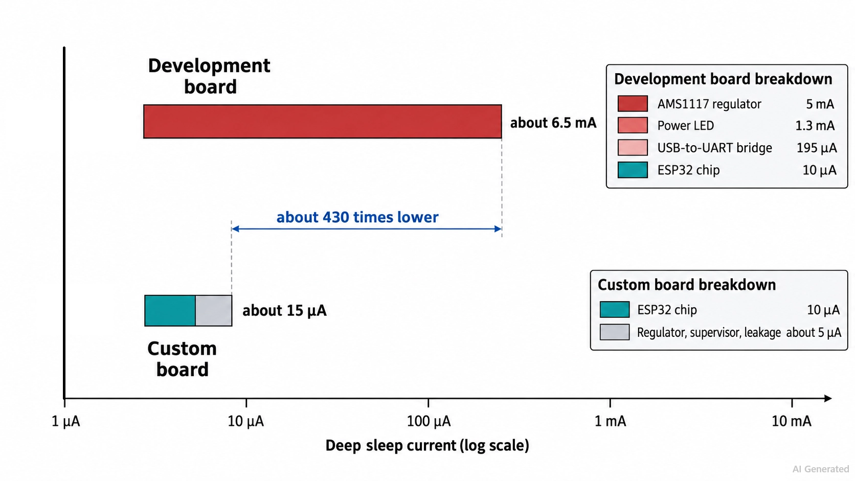
Figure: ESP32 development board vs custom board deep sleep current
On many low-cost boards, the main contributors are the regulator, a power LED, and the USB-to-UART bridge. The bridge converts USB to the universal asynchronous receiver-transmitter (UART) port used for programming.
| Source on the Board | Typical Draw | Basis |
|---|---|---|
| AMS1117-3.3 regulator | 5 mA quiescent, 11 mA maximum | AMS1117 datasheet, 1.5 V to 12 V input-to-output difference |
| Power LED with a 1 kΩ resistor | About 1.3 mA | (3.3 V − 2.0 V) ÷ 1 kΩ, assuming a 2.0 V forward voltage |
| CP2102N USB-to-UART bridge | 195 µA in USB suspend, 1.3 mA held in reset | CP2102N datasheet, when powered from the 3.3 V rail |
| ESP32 chip in deep sleep | 10 µA | ESP32 datasheet, RTC timer, and RTC memory |
| Total | About 6.5 mA | About 650 times the chip's own current |
These parts are typical of many boards, not all, so check your schematic. The guide to choosing an ESP32 development board compares common development boards. To reach microamps, measure a bare module or a custom board.
How to Reduce ESP32 Power Consumption on a Custom PCB
A custom PCB approaches the chip's deep sleep mode when the regulator, supply, and sleep loads are chosen to draw low current.
Choose a Regulator by Quiescent Current and Output Current
Quiescent current is the current a regulator draws to operate, and in deep sleep, it adds directly to the ESP32's floor. The regulator must also carry the transmit peaks; Espressif recommends a 3.3 V supply rated at 500 mA or more.
| Regulator | Typical Quiescent Current | Rated Output Current | Fit for a Battery-Powered ESP32 |
|---|---|---|---|
| AMS1117-3.3 | 5 mA | 1 A | Poor: quiescent current is 500 times the chip's 10 µA |
| MCP1700-3.3 | 1.6 µA | 250 mA | Poor: output is below the recommended 500 mA |
| RT9080-33 | 2 µA | 600 mA | Suitable: meets both requirements |
Selection rule: Choose the lowest quiescent current that still meets the 500 mA rating and holds regulation at your battery's lowest working voltage.
Dropout voltage sets the lowest voltage. The RT9080's 0.31 V dropout at 600 mA means a 3.3 V output needs about 3.6 V at full load. The AMS1117's typical 1.1 V dropout at 800 mA requires about 4.4 V, which is above the fully charged 4.2 V of a lithium-ion cell. For higher input voltages, a buck converter with a light-load mode can be more efficient than a low-dropout (LDO) regulator.
Size the Supply for Transmit Peaks and Low Battery Voltage
A low-power supply still has to deliver hundreds of milliamps for short periods:
- Peak current: The ESP32-WROOM-32E datasheet lists a peak current of 379 mA during 802.11b transmission at +19.5 dBm. A regulator rated for 250 mA can drop out of regulation during that burst.
- Bulk capacitance: Espressif's hardware design guidelines recommend at least 10 µF of capacitance at the main power entry, with 0.1 µF capacitors near the digital supply pins.
- Low-voltage reset: Espressif recommends a supply-voltage supervisor in battery-powered designs to keep CHIP_PU low when the supply is too low to boot.
How to Calculate ESP32 Battery Life from Average Current
Battery life depends on average current, not on the deep sleep figure alone. Average the active and sleep currents over one full cycle, then divide the usable battery capacity by that average.
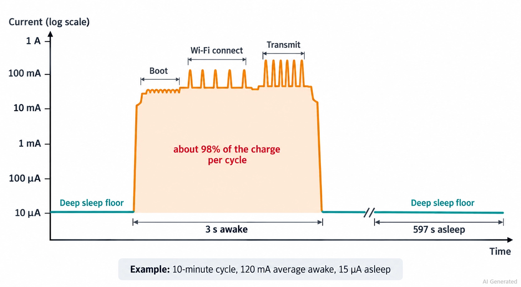
Figure: ESP32 current over one wake cycle
- Average current = (active current × active time + sleep current × sleep time) ÷ cycle time
- Battery life in hours = usable capacity in mAh ÷ average current in mA
A worked example, with these assumptions:
- Wake cycle: one reading every 10 minutes, 3 seconds awake at an assumed 120 mA average, within the chip's 95 to 240 mA radio range.
- Sleep current: 15 µA on a custom board, the chip's 10 µA plus an assumed 5 µA for the regulator, supervisor, and leakage.
- Capacity: 1,600 mAh usable from a 2,000 mAh cell, an assumed 80% derating.
The custom board draws 120 mA × 3 s = 360 mA·s awake and 0.015 mA × 597 s = 8.96 mA·s asleep. The average is 368.96 mA·s ÷ 600 s = 0.615 mA, so 1,600 mAh ÷ 0.615 mA gives about 2,600 hours.
| Design | Sleep Current | Wake Interval | Average Current | Estimated Life |
|---|---|---|---|---|
| Custom board | 15 µA | 10 minutes | 0.615 mA | About 2,600 hours, or 108 days |
| Development board | 6.5 mA | 10 minutes | 7.07 mA | About 226 hours, or 9.4 days |
| Custom board | 15 µA | 60 minutes | 0.115 mA | About 13,900 hours, or 1.6 years |
On the custom board, the 3s awake period accounts for about 98% of the charge per cycle. Shortening it, or waking less often, is the next improvement.
How to Measure ESP32 Average Current
A single multimeter reading in deep sleep does not represent the average current. Instead:
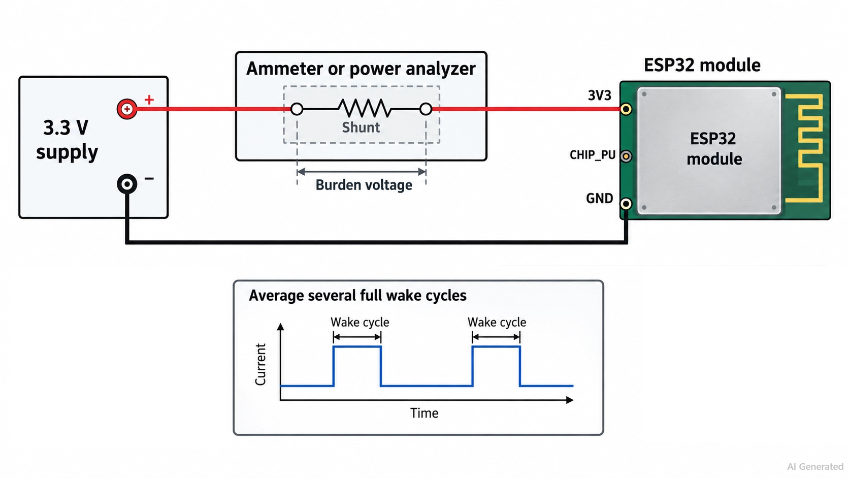
Figure: Measurement setup with an ammeter
- Measure the right hardware: a bare module or a custom board, not a development board.
- Cover the full range: use a power analyzer or source-measure unit that records microamps to hundreds of milliamps in one continuous capture.
- Watch the burden voltage: the drop across a meter's microamp-range shunt can pull the supply low enough to reset the chip during a transmission.
- Average whole cycles: record several complete wake cycles rather than one instant.
ESP32 Low-Power Design in JLCPCB PCB Assembly
At JLCPCB, advanced surface-mount technology (SMT) production lines and strict process control help ensure consistent solder joints on low-power boards, from the ESP32 module to the regulator.
JLCPCB supports fine-pitch SMT assembly with minimum IC pin pitches of 0.35 mm for Standard PCBA and 0.40 mm for Economic PCBA. Use the JLCPCB Parts Library to check stock and packaging for ESP32 modules and low-quiescent-current regulators before finalizing your bill of materials (BOM).
From ESP32 modules and low-quiescent-current regulators to fine-pitch SMT components, JLCPCB can help turn your low-power PCB design into an assembled board.
Conclusion
ESP32 power consumption depends on the mode and the board: the chip draws about 240 mA while transmitting, and 10 µA in deep sleep, but support circuitry can raise a board's sleep current into milliamps.
Use deep sleep when the device sleeps for minutes or longer, and power it from a regulator with a microamp quiescent current that still supplies 500 mA. Designing for average current, not the headline sleep figure, gives a realistic battery-life estimate.
Once your design is ready, upload your files to JLCPCB to review assembly options and get an instant quote.
FAQs About ESP32 Power Consumption
Q: How Much Current Does an ESP32 Draw in Deep Sleep?
About 10 µA for the ESP32 chip with only the RTC timer and RTC memory powered, per Espressif's datasheet. With the ULP coprocessor running, it draws 100-150 µA.
Q: Why Does My ESP32 Draw Milliamps in Deep Sleep?
Usually, because of the board, not the chip. The regulator's quiescent current, a power LED, and the USB-to-UART bridge can stay powered while the ESP32 sleeps.
Q: Does an ESP32 Stay Connected to Wi-Fi in Deep Sleep?
No. Wi-Fi and Bluetooth connections are not maintained in deep sleep or light sleep. To stay connected at low power, use a Wi-Fi modem with automatic light sleep.
Q: Which Uses Less Power, Light Sleep or Deep Sleep?
Deep sleep, at about 10 µA, against 0.8 mA for light sleep at the chip level. For very short intervals, the energy to reboot and reconnect can make light sleep more efficient overall.
Q: How Long Can an ESP32 Run on a Battery?
It depends on the average current. A custom board with 15 µA sleep current, waking every 10 minutes for 3 s at 120 mA, averages 0.615 mA: about 108 days on 1,600 mAh.
Popular Articles
• PCB Silkscreen: All You Need to Know
• The Comprehensive Guide to Circuit Symbols: Key to Understanding Electrical and Electronic Diagrams
• Design Guidelines for PCB Using FR4 Substrates
• Choosing the Best PCB Color-Enhancing Aesthetics and Functionality
• PCB Board Design: A Step-by-Step Guide for Beginners
Keep Learning
ESP32 Power Consumption Explained: Current Draw, Sleep Modes, and Battery Life
Key Takeaways Power consumption by mode: The ESP32 draws around 240 mA during Wi-Fi transmission, 0.8 mA in light sleep, and just 10 µA in deep sleep, based on Espressif's typical datasheet figures. Deep sleep current: The ESP32 can draw 10 µA in deep sleep, with only the RTC timer and memory remaining powered. Keeping the ULP coprocessor running increases current consumption to around 100–150 µA. Development board power consumption: A typical ESP32 development board can draw around 6.5 mA even in dee......
ESP32 Pinout Reference: Which GPIO Pins Are Safe to Use and Avoid?
Key Takeaways GPIO count: The ESP32 chip has 34 GPIOs, and the ESP32-WROOM-32E module exposes 26 of them. General-purpose pins: Fifteen module GPIOs carry no boot, flash, or input-only restrictions: GPIO4, GPIO13, GPIO14, GPIO16 to GPIO19, GPIO21 to GPIO23, GPIO25 to GPIO27, GPIO32, and GPIO33. Strapping pins: GPIO0, GPIO2, GPIO5, GPIO12, and GPIO15 are sampled at reset, so any circuit connected to them must maintain the level required by the boot mode. Input-only pins: GPIO34, GPIO35, GPIO36, and GPI......
PCB Silkscreen: All You Need to Know
Key Takeaways The PCB Silkscreen Guide demonstrates that a properly designed legend layer is essential to prevent assembly failures and ensure long-term hardware reliability. By mastering modern manufacturing methodologies like Direct Legend Printing (DLP) and aligning layouts with JLCPCB's strict DFM design rules—including the absolute 0.8 mm character height limit and the automated 0.15 mm silkscreen clipping protocol driven by solder mask precedence—engineers can seamlessly eliminate cold joints an......
A Beginner's Guide to Basic Electronic Components: Functions, Symbols & Uses
Every circuit, from a simple LED flashlight to a microcontroller board, is built from the same handful of common electronic components. This guide breaks down the ten basic electronic components you will encounter most often: What each component does How it works Key specifications Where engineers use it By the end, you will be able to recognize these electronic circuit components on a schematic, a PCB, or a parts bin, and know exactly why each one is there. These electronic components are the buildin......
How to Read and Create PCB Schematics
Key Takeaways Read Schematics: Understand symbols, net labels, and component values. Design in EasyEDA: Place components and create circuit connections. Run Design Checks: Use ERC and DRC to identify potential issues. Verify Components: Check pin assignments and PCB footprints. Prepare for Manufacturing: Validate PCB layouts and manufacturing files. Printed circuit board (PCB) design begins with a clear understanding of how the electronic circuit should function. A schematic diagram represents the cir......
Maximizing Circuit Reliability with PCB Test Points and Smart DFT
Key Takeaways Early Fault Catching: Test points drastically reduce diagnosis time and prevent costly field failures. Standard Pad Sizing: Use 1.0 mm flat copper pads with 2.54 mm spacing for optimal fixture contact. Protect High-Speed Signals: Keep branch traces short to prevent capacitive loading and resonance. Single-Sided Access: Place all test pads on the bottom layer to cut fixture costs. Right Test for Volume: Use flying probe for prototypes and bed-of-nails ICT for mass production. A PCB test p......