Relay Pinout Explained: Diagrams, Pin Functions & Multimeter Testing
13 min
- Introduction
- Relay Pinout Diagram: Pin Functions for 4-Pin, 5-Pin, and 8-Pin Relays
- Relay Pinout: Coil, COM, NO, and NC Functions
- 5-Pin Relay Pinout: SRD-05VDC-SL-C SPDT Relay
- 4-Pin Relay Pinout: SPST Form A and Form B Relays
- 8-Pin Relay Pinout: DPDT PCB and Octal Plug-In Relays
- Automotive Relay Pinout: Pins 30, 85, 86, 87, and 87a
- Relay Terminal Numbering: Automotive, Industrial, and PCB Relays
- Relay Module Pinout: Header Pins and COM, NO, and NC Terminals
- How to Identify Relay Pins with a Multimeter
- Conclusion
- FAQs About Relay Pinout
Key Takeaways
- Pin functions: A standard electromechanical relay has two coil pins, and each pole adds a common (COM), normally open (NO), and normally closed (NC) pin.
- Viewing side: Relay footprints are often drawn in bottom view, with the pins facing you. When a drawing does not state its view, confirm NC and NO with a continuity check.
- Relay Pin Count: A 5-pin relay is typically SPDT, a 4-pin relay is usually SPST, and an 8-pin relay is commonly DPDT. However, pin arrangements can vary between PCB, automotive, and octal relays.
- Automotive Relay Pins: Car relays use standard terminal numbers: 85 and 86 for the coil, 30 for common (COM), 87 for normally open (NO), and 87a for normally closed (NC).
- Testing with a Multimeter: Identify the coil pins by measuring their resistance. With the coil off, COM and NC should show continuity. When the coil is energized, COM disconnects from NC and connects to NO.
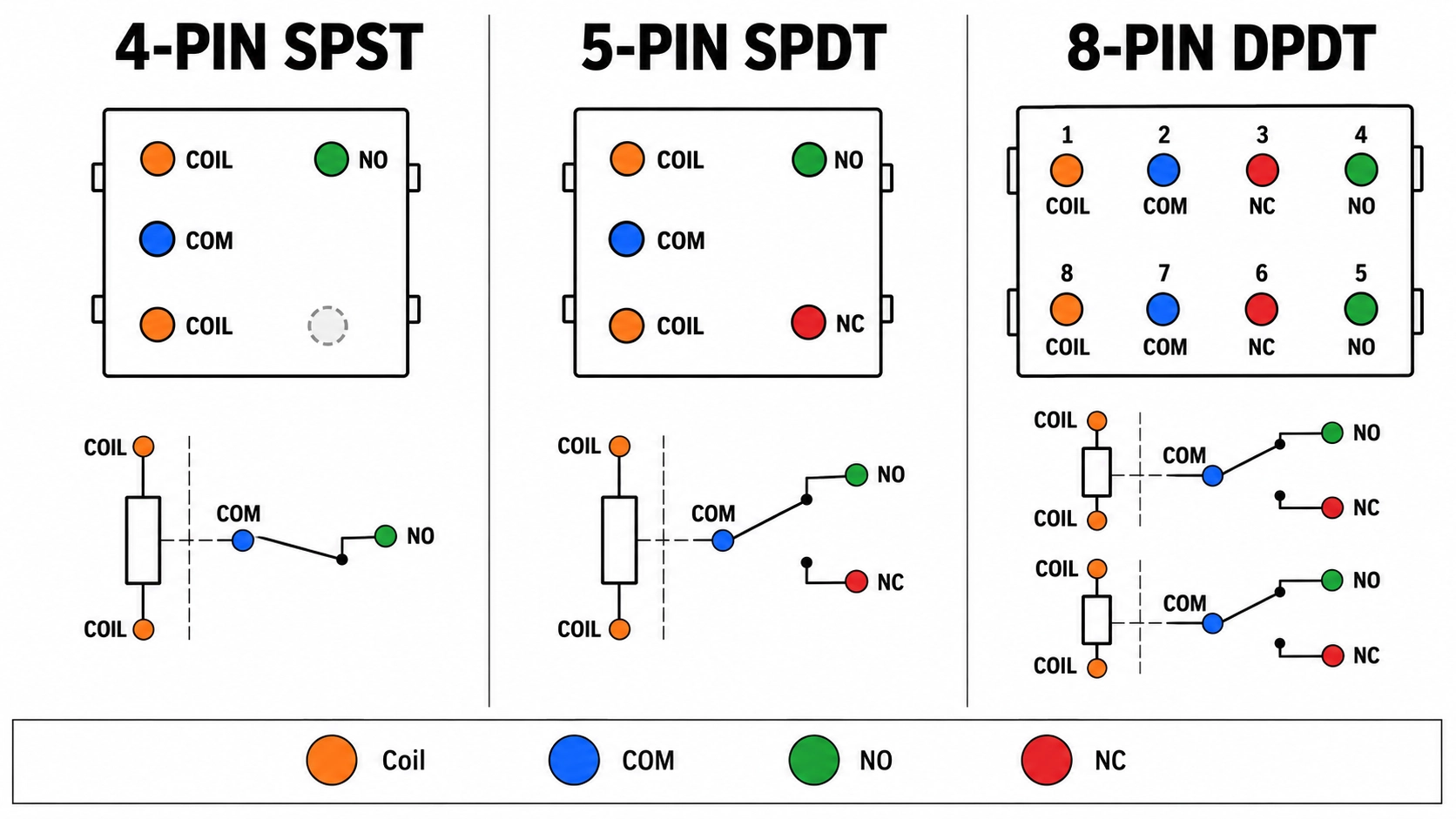
Figure: Relay pinout diagram comparing 4-pin, 5-pin, and 8-pin relays, with pins color-coded by function.
Introduction
A relay pinout shows the position and function of each terminal. On common electromechanical relays, these terminals connect to the coil and the switching contacts, such as COM (common), NO (normally open), and NC (normally closed).
Pin layouts vary by relay type and model. PCB relays, automotive relays, and 8-pin plug-in relays may use different layouts and numbering conventions. Before wiring, check the exact model’s pinout diagram and whether it shows a top or bottom view.
In this guide, you will learn:
- What the coil, COM, NO, and NC terminals do
- Common 4-pin, 5-pin, and 8-pin relay pinouts
- Automotive relay terminal numbers and their functions
- Relay module header and terminal connections
- How to identify unmarked relay pins with a multimeter
Relay Pinout Diagram: Pin Functions for 4-Pin, 5-Pin, and 8-Pin Relays
A relay pinout has two coil pins, plus a COM pin and an NO pin, an NC pin, or both for each pole. The pin count usually indicates the contact form: 4 pins for SPST, 5 pins for SPDT, and 8 pins for DPDT.
| Relay Type | Pins | Coil | COM | NO | NC |
|---|---|---|---|---|---|
| SPST Form A, such as SRD-05VDC-SL-A | 4 | Coil end | Between the coil pins | Far-end corner | None |
| SPST Form B | 4 | Coil end | Between the coil pins | None | Far-end corner |
| SPDT, such as SRD-05VDC-SL-C | 5 | Coil end | Between the coil pins | Far-end corner | Far-end corner |
| DPDT PCB relay, such as HK19F | 8 | 1, 8 | 2, 7 | 4, 5 | 3, 6 |
| DPDT octal plug-in relay | 8 | 2, 7 | 1, 8 | 3, 6 | 4, 5 |
| Automotive SPST | 4 | 85, 86 | 30 | 87 | None |
| Automotive SPDT | 5 | 85, 86 | 30 | 87 | 87a |
Note
Pin numbering and physical arrangements vary by relay model. The HK19F and octal relay examples use different pin configurations. Always refer to the manufacturer's datasheet and confirm the viewing direction before wiring.
Once you've verified your relay's pinout and footprint and finalized the PCB layout, upload your Gerber files to JLCPCB for a PCB quote.
For assembly, add your BOM and CPL files to review component availability and assembly pricing.
Relay Pinout: Coil, COM, NO, and NC Functions
When the relay coil is de-energized, COM is connected to NC. When the rated voltage is applied to the coil, the electromagnetic force moves the armature, switching COM from NC to NO.
The four main relay pin functions are:
- Coil pins: The two terminals of the electromagnetic winding that energize the relay. They are electrically isolated from the contact circuit.
- COM (Common): The moving contact that switches between NC and NO.
- NO (Normally Open): Disconnected from COM when the coil is de-energized; connected to COM when energized.
- NC (Normally Closed): Connected to COM when the coil is de-energized; disconnected when energized.
The number and arrangement of relay pins depend on the contact configuration. For example, a typical 5-pin SPDT relay has two coil terminals and three contact terminals: COM, NO, and NC.
In circuit schematics, relay pins are represented by a coil and a set of switch contacts. See our relay symbol guide to understand how these components are represented in circuit diagrams. The same pole-and-throw terminology applies to switches, as explained in our switch symbol guide.
5-Pin Relay Pinout: SRD-05VDC-SL-C SPDT Relay
On the SRD-05VDC-SL-C, COM sits between the two coil pins at one end of the relay, and NC and NO sit at the two corners of the opposite end. The datasheet drilling plan fixes their positions.
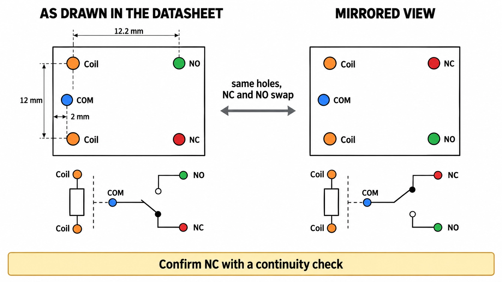
Figure: SRD-05VDC-SL-C relay pinout, with COM between the coil pins, NC and NO at the far end.
- Coil pins: Two pins 12 mm apart at the coil end.
- COM: Midway between the coil pins, offset 2 mm toward the outer edge of the relay.
- NC and NO: One at each far-end corner, 12.2 mm from the coil pins.
The part number also encodes the contact form. In SRD-05VDC-SL-C, "05VDC" is the coil voltage, "L" is the 0.36 W coil, and "C" is Form C, the 5-pin changeover version.
The SRD datasheet shows its drilling plan and wiring diagram without stating whether they are top or bottom views. The pin pattern is symmetric about the line through COM, so the relay also fits a footprint drawn from the other side, but NC and NO then swap positions. Confirm which far-end pin is NC by performing a continuity check before finalizing the footprint.
4-Pin Relay Pinout: SPST Form A and Form B Relays
A 4-pin SPST relay keeps the coil pins and COM of the 5-pin layout but drops one contact pin. A Form A relay keeps NO, and a Form B relay keeps NC.
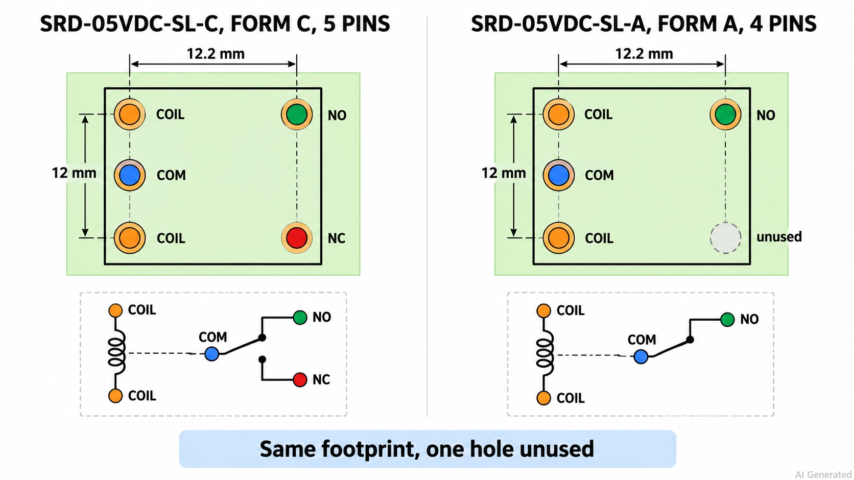
Figure: SRD-05VDC-SL-A and SRD-05VDC-SL-C on the same footprint, with the unused NC position grayed out.
The last letter of an SRD part number names the contact form:
- Form A, SPST-NO: The SRD-05VDC-SL-A has 4 pins. COM connects to NO only while the coil is energized, which suits loads that should stay off by default.
- Form B, SPST-NC: COM stays connected to NC until the coil is energized, which suits loads that should stay on by default.
- Form C, SPDT: The 5-pin SRD-05VDC-SL-C carries both NO and NC.
Because the remaining pins keep their Form C positions, a board laid out for the 5-pin footprint typically accepts the 4-pin version, with one hole left unused.
8-Pin Relay Pinout: DPDT PCB and Octal Plug-In Relays
Most 8-pin relays are DPDT: two coil pins plus COM, NO, and NC for each of two poles. The numbering is not universal. An 8-pin PCB relay and an 8-pin octal relay use the same pinout for different functions.
8-Pin PCB Relay Pinout — HK19F
The HK19F datasheet draws a bottom view with two rows of four pins. The coil pins are at one end, and each row carries one pole in the order COM, NC, and NO.
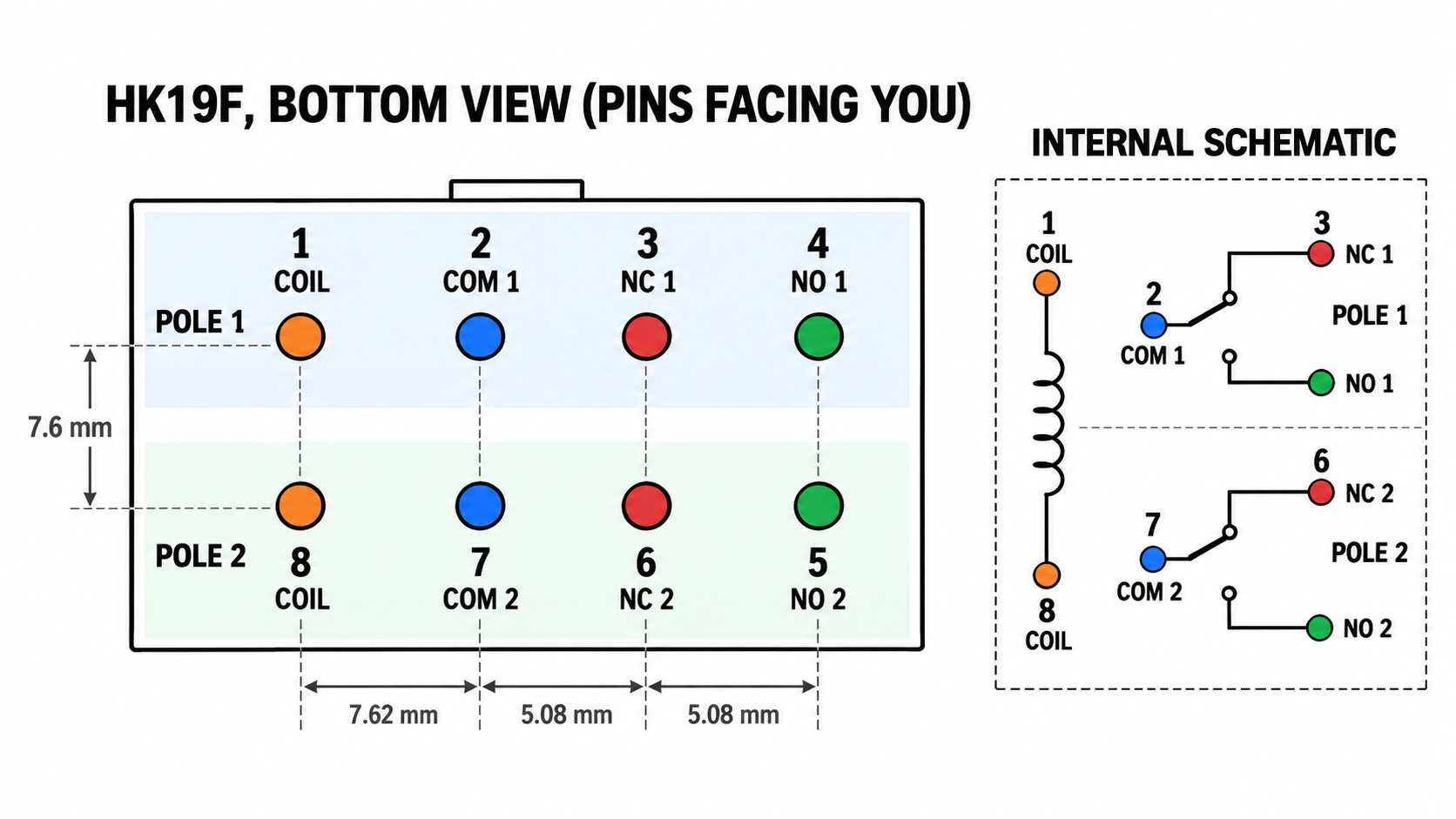
Figure: HK19F 8-pin DPDT relay pinout in bottom view, with coil, COM, NC, and NO pins numbered 1 to 8.
Numbering the pins 1 to 8 around the package, starting at a coil pin, gives:
- Coil: Pins 1 and 8.
- Pole 1: COM on pin 2, NC on pin 3, and NO on pin 4.
- Pole 2: COM on pin 7, NC on pin 6, and NO on pin 5.
The HK19F drawing itself does not print PINs, and footprint libraries number the pins in different orders. The EasyEDA footprint for the HK19F-DC5V-SHG numbers them column by column. The coil is 1 and 2; COM is 3 and 4; NC is 5 and 6; and NO is 7 and 8.
8-Pin Octal Relay Pinout
An octal relay plugs into a round 8-pin socket with a keyed center post, and the pins are numbered 1 to 8 around the key. Most general-purpose octal DPDT relays, such as the Finder 60.12, use this assignment:
- Coil: Pins 2 and 7.
- Pole 1: COM on pin 1, NO on pin 3, and NC on pin 4.
- Pole 2: COM on pin 8, NO on pin 6, and NC on pin 5.
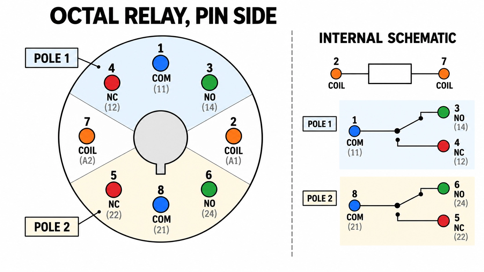
Figure: 8-pin octal relay socket pinout, showing pins 1 to 8 around the keyed center post with both poles shaded.
Pin 1 is COM on an octal relay, but a coil pin on the HK19F. Check the diagram printed on the relay case before you reuse a pin assignment from another 8-pin relay.
Automotive Relay Pinout: Pins 30, 85, 86, 87, and 87a
On an automotive relay, 85 and 86 are the coil, 30 is the common contact, 87 is normally open, and 87a is normally closed. The numbers come from DIN 72552 and are printed beside each blade terminal or on the case diagram.
- 85 and 86: DIN 72552 assigns 86 to the coil positive and 85 to the coil negative.
- 30, common: The contact input, typically fed from the supply.
- 87, normally open: Connects to 30 while the coil is energized.
- 87a, normally closed: Connects to 30 while the coil is off.
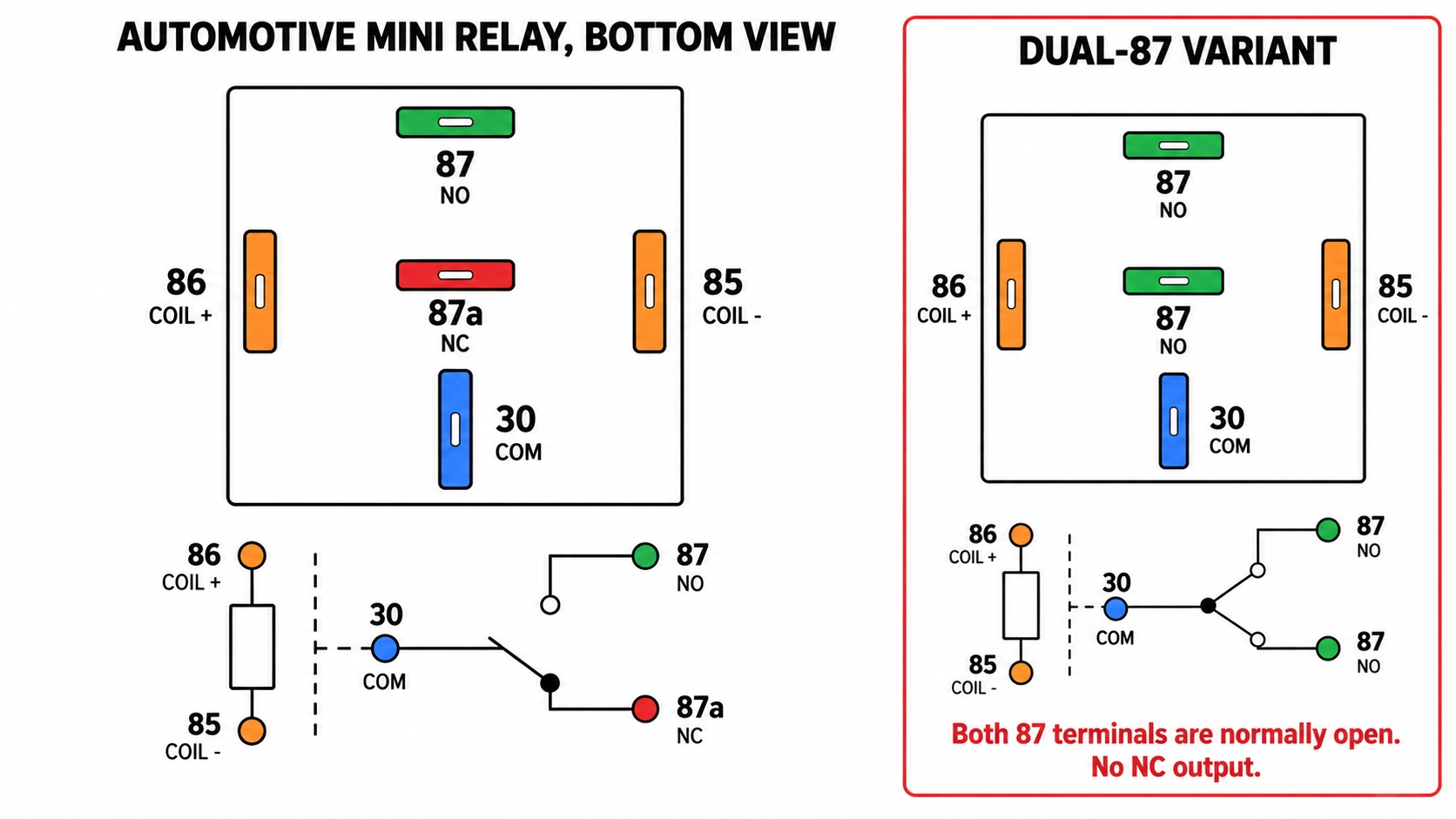
Figure: Automotive ISO mini relay pinout in bottom view, showing pins 30, 85, 86, 87, and 87a, with a dual-87 inset.
On a typical ISO mini relay, such as the Omron G8JN, the bottom view places 87 and 30 at opposite ends. 87a sits in the center, and 85 and 86 sit on the two remaining sides. Some variants move terminals, so read the number beside each blade rather than relying on position alone.
Some 5-pin relays carry two 87 terminals instead of 87a. Both are normally open outputs, so this relay cannot supply a circuit that must remain on while the coil is off. Read the second number before assuming it is 87a.
If the case shows a diode across the coil, connect 86 to positive and 85 to ground. Reversed polarity forward-biases the diode and can draw excessive current from the coil supply.
Relay Terminal Numbering: Automotive, Industrial, and PCB Relays
Relay terminal markings vary depending on the application and identification convention. Automotive relays commonly use DIN 72552 terminal numbers, while industrial control relays often follow EN 50005 markings. PCB relays typically use pin numbers or functional labels such as COM, NO, NC, A1, and A2, depending on the manufacturer.
| Pin Function | PCB Relay (Typical Labels) | Automotive Relay (DIN 72552) | Industrial Relay (EN 50005) |
|---|---|---|---|
| Coil terminal 1 | Coil | 86 (typically positive) | A1 |
| Coil terminal 2 | Coil | 85 (typically negative) | A2 |
| Common | COM | 30 | 11 |
| Normally closed | NC | 87a | 12 |
| Normally open | NO | 87 | 14 |
In EN 50005 numbering, the first digit denotes the pole, and the second denotes the function: 1 for COM, 2 for NC, and 4 for NO. So 21, 22, and 24 are the COM, NC, and NO pins of the second pole.
Relay Module Pinout: Header Pins and COM, NO, and NC Terminals
A relay module has two groups of pins. The VCC, GND, and IN headers provide power and control to the board, while the COM, NO, and NC screw terminals connect to the relay contacts.
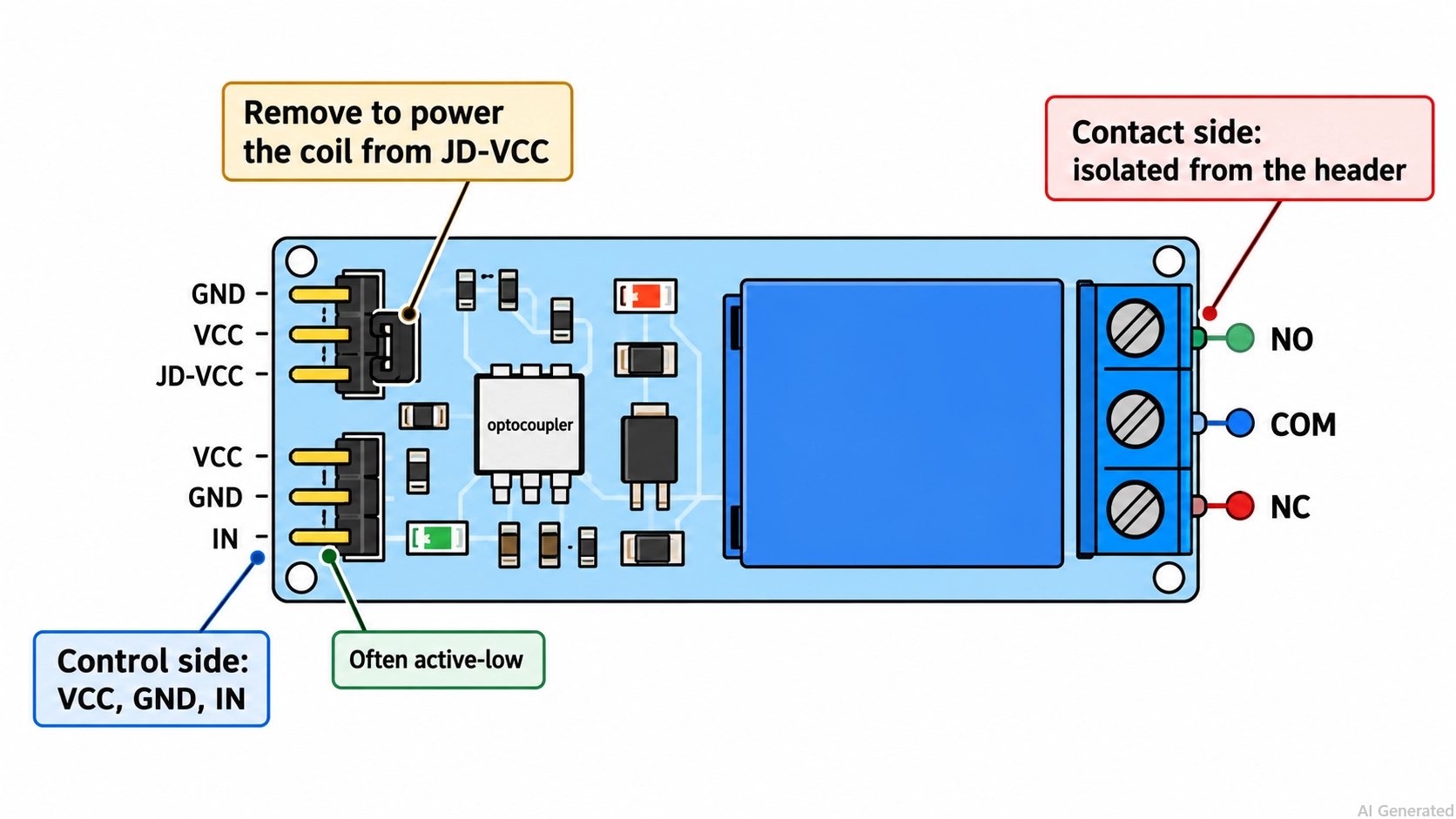
Figure: Relay module pinout, showing the VCC, GND, and IN header, the COM, NO, and NC screw terminals, and the JD-VCC jumper.
- VCC: The module supply, usually equal to the relay coil voltage, such as 5 V for a 5 V relay.
- GND: The supply and signal ground.
- IN: The control input, labeled IN1, IN2, and so on for multi-channel boards. On many optocoupler-isolated modules, the input is active-low: pulling IN low energizes the relay.
- COM, NO, and NC: The relay contacts are brought out to the screw terminal and isolated from the header pins.
On optocoupler-isolated modules, a jumper links VCC to JD-VCC. Removing it allows a separate supply on JD-VCC to power the relay coils, keeping the coil current off the controller's supply.
How to Identify Relay Pins with a Multimeter
Find the coil by resistance first, then find COM and NC by continuity with the coil off, and confirm NO with the coil energized. You need a multimeter and a bench supply set to the rated coil voltage.
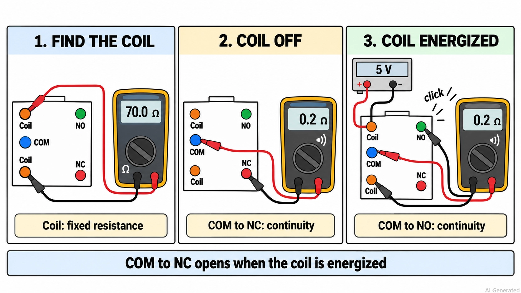
Figure: Identifying relay pins with a multimeter: coil resistance, COM to NC at rest, and COM to NO with the coil energized.
- Isolate the relay: remove it from the circuit or test a loose part to prevent other components from affecting the readings.
- Find the coil pins: Measure resistance between each pin pair. The coil is the pair that reads a fixed resistance, typically in the tens to thousands of ohms range, such as 70 Ω on the SRD-05VDC-SL-C. Contact pairs read near zero or open.
- Find COM and NC: With the coil unpowered, find the contact pair that shows continuity. One pin is COM, and the other is NC.
- Energize the coil: Apply the rated coil voltage across the coil pins. If the case shows a diode symbol or a polarity mark such as 86, A1, or +, connect the positive supply to that pin. The relay typically clicks as the armature moves.
- Find NO: The COM–NC pair now opens. The pin that connects to one of them is NO, and the pin it connects to is COM.
- Confirm the result by removing the coil voltage. COM should return to NC.
| Pin Pair | Coil Off | Coil Energized |
|---|---|---|
| Coil to coil | Coil resistance | Coil resistance |
| COM to NC | Continuity, near 0 Ω | Open |
| COM to NO | Open | Continuity, near 0 Ω |
| NC to NO | Open | Open |
| Coil to any contact | Open | Open |
Conclusion
Most relays share the same pin functions: two coil pins, plus COM, NO, and NC for each pole. Before connecting a relay to your circuit, use a multimeter to identify the coil pins and check contact continuity in both energized and de-energized states. Always compare your findings with the datasheet and verify the viewing orientation, especially when designing a PCB footprint.
FAQs About Relay Pinout
Which Pin Is COM on a Relay?
COM is the pin that connects to NC with the coil off and to NO with the coil energized. On the SRD relay, it sits between the coil pins; on a car relay, it is pin 30.
Are Relay Coil Pins Polarized?
Usually not. A plain coil works in either direction, but a coil with a built-in suppression diode needs the marked polarity, typically 86 or A1 positive.
What Is 87a on a Relay?
87a is the normally closed contact on an automotive relay. It connects to pin 30 while the coil is off and opens when the coil is energized.
How Do I Find the Coil Pins Without a Datasheet?
Measure resistance between every pin pair. The coil pair reads a fixed resistance, typically tens to thousands of ohms, while the contact pairs read near zero or open.
Is a 5-Pin Car Relay the Same as a 5-Pin PCB Relay?
No. Both are usually SPDT, but a car relay uses plug-in blades numbered 30, 85, 86, 87, and 87a, while a PCB relay, such as the SRD, has unnumbered solder pins.
Popular Articles
• PCB Silkscreen: All You Need to Know
• The Comprehensive Guide to Circuit Symbols: Key to Understanding Electrical and Electronic Diagrams
• Design Guidelines for PCB Using FR4 Substrates
• Choosing the Best PCB Color-Enhancing Aesthetics and Functionality
• PCB Board Design: A Step-by-Step Guide for Beginners
Keep Learning
Relay Pinout Explained: Diagrams, Pin Functions & Multimeter Testing
Key Takeaways Pin functions: A standard electromechanical relay has two coil pins, and each pole adds a common (COM), normally open (NO), and normally closed (NC) pin. Viewing side: Relay footprints are often drawn in bottom view, with the pins facing you. When a drawing does not state its view, confirm NC and NO with a continuity check. Relay Pin Count: A 5-pin relay is typically SPDT, a 4-pin relay is usually SPST, and an 8-pin relay is commonly DPDT. However, pin arrangements can vary between PCB, ......
How to Connect and Choose a Flyback Diode for a Relay
Key Takeaways Diode Placement: Connect the flyback diode across the relay coil, with its cathode connected to the positive side and its anode to the negative side. Why It Matters: When the relay switches off, the diode provides a safe path for the remaining coil current, preventing a high-voltage spike that could damage the transistor. Choosing the Right Diode: Select a diode with a reverse-voltage rating above the coil supply voltage and a forward-current rating suitable for the coil current. Common ......
A Beginner's Guide to Basic Electronic Components: Functions, Symbols & Uses
Every circuit, from a simple LED flashlight to a microcontroller board, is built from the same handful of common electronic components. This guide breaks down the ten basic electronic components you will encounter most often: What each component does How it works Key specifications Where engineers use it By the end, you will be able to recognize these electronic circuit components on a schematic, a PCB, or a parts bin, and know exactly why each one is there. These electronic components are the buildin......
Reliable BMS Boards Start With Quality PCB Manufacturing
Key Takeaways Dual Duty: BMS PCBs handle heavy currents and millivolt sensing simultaneously, requiring strict layout isolation. Power & Heat: Currents over 10A need 2 oz+ copper pours with via stitching to drop resistance and heat. Clean Sensing: Kelvin differential routing and split grounds prevent load noise from corrupting cell voltage readings. Materials & Finish: High-Tg FR-4 and ENIG surface finishes ensure heat tolerance and flat mounting pads. DFM & Testing: Design for heavy-copper etch toler......
What is Solder Mask and How Does it Impact Your PCB Designs?
Solder mask may not be the most exciting topic in PCB manufacturing, but it's definitely one of the most crucial. Without proper solder mask, your Printed Circuit Boards (PCB's) could suffer from shorts, bridges, corrosion, and other costly and time-consuming issues. So, if you want to ensure the quality, reliability, and longevity of your electronic products, you need to know everything about solder mask - from it's purpose and types to it's application and design implementations. In this ultimate gu......
Understanding Fast Turn PCB: Accelerating Your Electronic Designs
Fast Turn PCB is a quick method to create printed circuit boards (PCBs) to satisfy strict project deadlines. As technology advances so rapidly these days, people more and more desire quicker prototype and computer part manufacturing. Fast Turn PCB services help engineers and designers move quickly from concept to production, which leads to new products in many fields. This article discusses what are Fast Turn PCBs, what they can do for you, and how to choose the best provider to get quality and speed.......